practical wireless số 2006 09
Bạn đang xem bản rút gọn của tài liệu. Xem và tải ngay bản đầy đủ của tài liệu tại đây (8.94 MB, 68 trang )
September 2006 £3.00
pwp
pwp
plus much
more and all
your favourite
regulars
R 37
Antenna
Test
Comet H-422
Four-Band
Rotary V Dipole
Antenna
Test
Comet H-422
ra ica P ect
Practical Projects
Simple RF Test
Equipment
Show Time!
Leicester Amateur Radio
Show Insight
Climbing Ladders of
Attenuation
Network Design Ideas
Copyright © PW PUBLISHING LTD. 2006. Copyright in all drawings, logos, photog aphs and articles published in Practical Wireless is fu ly p otected and ep oduction in whole or part is exp essly forbidden.
All reasonable precautions are taken by Practical Wireless to ensu e that the advice and data given to our eaders a e eliable. We canno however gua antee it and we cannot accept legal responsibil ty
for t Prices a e those current as we go to p ess.
Published on the second Thursday of each month by PW Publ shing Ltd., Arrowsm th Court, Station App oach, B oadstone, Dorset BH18 8PW. Tel: 0870 224 7810 Printed in England by Holb ooks P inte s Ltd.,
Portsmouth P03 5HX Distributed by Seymour, 86 Newman St eet, London , W1P 3 D, Tel: 0207-396 8000, Fax: 0207-306 8002, Web http //www seymour co uk. Sole Agents for Aust alia and New Zealand -
Go don and Gotch (Asia) Ltd.; South Africa - Cent a News Agency. Subscriptions INLAND £32, EUROPE £40, REST OF WOR D £49, payable to PRACTICAL WIRELESS, Subscription Department PW
Pub ishing Ltd., Arrowsm th Court, Station App oach, Broadstone, Dorset BH18 8PW. Tel: 0870 224 7830 PRACTICAL WIRELESS is sold subject to the following conditions, namely that it shall not, w thout
written consent of the publishe s fi s having been given, be lent, e-sold, hired out or otherwise disposed of by way of t ade at more than the ecommended selling price shown on the cover, and that it shall
not be lent, re-sold, hi ed out or othe wise disposed of in a mutilated condition or in any unauthorised cover by way of T ade, or affixed to or as part of any publication or advertising, lite ary or pictorial
matter whatsoever Practical Wireless is Publ shed monthly for $50 per year by PW Publishing Ltd., Ar owsm h Court, Station App oach, B oadstone, Dorset BH18 8PW, Royal Mail International, c/o
Yellowstone International, 87 Burlews Court, Hackensack, NJ 07601. UK Second Class Postage pa d at South Hackensack. Send USA add ess changes to Royal Mail Inte national, c/oYellowstone
Inte national, 2375 Pratt Bouleva d, Elk G ove Village, IL 60007-5937. The USPS (United States Postal Se vice) number for Practical Wi eless is: 007075.
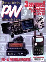
The Comet antenna is
shown in use at GB0SH at
Strumble Head Lighthouse
on the Pembrokeshire
Coast in Wales. As far as
Nevada (Comet
distributors in the UK) are
aware this was the first
time that the Strumble
Head Lighthouse has had
an Amateur station
transmitting from inside
the building. Enjoy this
issue, see you next time.
Cover subject
15 Friedrichshafen 2006
A round-up of the news and sights from the
second biggest Amateur Radio show in the
world.
16 Doing it By Design
Try your hand at building Tony Nailer
G4CFY’s basic double sideband generator
for 7MHz.
18 Comet H-422 Four-Band Rotary
Dipole Review
Carl Mason GW0VSW, has been testing,
what turned out to be a versatile antenna
from the Comet range. If you’re looking for
a rotary dipole he says it has to be worth a
look!
22 Simple RF Test Equipment
Stocking your radio shack with the basic
necessities is a must for every budding
home-brew enthusiast, so what better place
to start than by building your own test gear?
Tim Walford G3PCJ gets you started.
25 Ladders Of Attenuation
Stefan Niewiadomski urges you to climb
the ‘rungs’ of ladder attenuators. They may
prove to be easier to use than you think.
32 T4-2 The Station Aid
Get busy and have a go at ‘brewing-up’
Rob Hannan G4RQJ’s adapter for remote
radio-monitoring.
36 Leicester Amateur Radio Show
It’s show time again! Whet your appetite and
get the low-down on what will be on offer at
Castle Donington this year with our insight
to one of the UK’s best loved Amateur
Radio shows.
41 Antenna Workshop
Bert Roberts G4XBZ looks into the
process of designing and erecting a flexible
all-band h.f. vertical antenna. You’ll only
need a few materials and plenty of
enthusiasm.
45 A Super-regenerative Receiver
for 144MHz
A classic v.h.f. project is re-visited here. It’s
still a viable project and could still be built
today.
48 Carrying on the Practical Way
George Dobbs G3RJV shares his ideas for
a glowing voltage indicator unit this month.
50 Valve & Vintage
Join Phil Cadman G4JCP in the vintage
wireless shop as he prepares for Russian
visitors as he commemorates an interesting
40th anniversary.
6 Keylines Topical chat
and comments from our
Editor, Rob Mannion
G3XFD. This month, he
discusses raising the hobby’s
profile among non-hobbyists.
7 Amateur Radio Waves
You have your say! Keep
those letters coming in and
making ‘waves’ with your
comments, ideas and
opinions.
8 Amateur Radio Rallies
A round-up of radio rallies
taking place in the coming
month.
9 Amateur Radio News &
Clubs Keep up-to-date with
the latest news, views and
product information from the
world of Amateur Radio with
our News pages. Also, find
out what your local club is
doing.
54 VHF DXer David Butler
G4ASR has reports of
tremendous Sporadic-E
openings on the v.h.f. bands.
56 HF Highlights The latest
news from the h.f. bands is
presented by Carl Mason
GW0VSW.
60 Book Store Check out
the biggest and best
selection of radio related
books anywhere, in our
bright and comprehensive
Book Store pages.
63 Bargain Basement
The bargains just keep on
coming! Looking for a
specific piece of kit? Check
out our readers’ ads, you
never know what you may
find!
64 Subscriptions Want to
make sure you don’t miss a
single issue of your favourite
radio read, then why not
subscribe to PW in one easy
step?
65 Topical Talk Rob
G3XFD discusses Brian
Catchpole M0TAD’s points
of view on the possibilities of
recycling Radio and
electronic equipment.
features
regulars
September 2006
On Sale 10 August
Vol. 82 No. 9 Issue 1193
(October Issue on sale 14 September)
Published by
PW Publishing Limited
Ar owsmith Court
Station App oach
BROADSTONE
Dorset BH18 8PW
Directors: Stephen Hunt & Roger Hall
Editorial Department
☎ 0870 224 7810
Fax: 0870 224 7850
Editor
Rob Mannion G3XFD/EI5IW
Production Editor
Donna Vincent G7TZB/M3TZB
Technical Editor
NG (Tex) Swann G1TEX/M3NGS
Art Department
☎ 0870 224 7820
Fax: 0870 224 7850
Art Editor
Stephen Hunt
Typesetting
Peter Eldrett
Sales Department
Fax: 0870 224 7850
Advertisements
Roger Hall G4TNT
☎ 0207 731 6222
Advertisement Administration
Joan Adams
☎ 0870 224 7820
Book Orders
☎ 0870 224 7830
Subscription Administration
Webscribe
Practical Wireless Subscriptions
PO Box 464
Berkhamsted
Hertfordshire HP4 2UR, UK
www.webscribe.co.uk
☎ 01442 879097
Fax: 01442 872279
Finance Department
☎ 0870 224 7840
Fax: 0870 224 7850
Finance Manager
Alan Burgess
Finance Assistant
Margaret Hasted
PW Publishing Website
www.pwpublishing.ltd.uk
Our 0870 numbers are charged at the BT Standard National Rate
Practical Wireless, September 2006
5
september 2006 contents
Design: Steve Hunt
Main Photograph: Courtesy of Tim Beaumont
M3SDE/ZK1SDE (supplied by Nevada)
Inset Photograph: Tim Walford G3PCJ
18
22
32
48
41
36
O
ver the two days , Thursday and
Friday 6 and 7th July I travelled to
East Anglia and the East Midlands.
The 551 mile (886km) round-trip from Dorset
was for a club visit and a meeting with
Norfolk based PW authors.
King’s Lynn Amateur Radio Club
(KLARC) in Norfolk welcomed me. Despite the
heat, everyone thoroughly enjoyed the
evening and we didn’t leave the beautifully
situated clubroom until after 11pm! I shall be
looking forward to another visit to KLARC in
the future.
My long journey was notable for a number
of reasons - not the least being that the air-
conditioning in my car was really earning its
keep! However, another reason - a recurring
question - (from people I met during the
journey) made me realise something must be
done to publicise Amateur Radio to the
general public!
Amateur Radio?
While parking my car at the Tesco in store in
Market Deeping, Lincolnshire for my lunch, I
was approached by one of the trolley
attendants. The man was over retirement age
but very alert in his part time job. Interested,
he asked about the EI5IW/G3XFD callsign
lettering in the rear window of my car. When I
gave him brief details, he asked, “What’s
Amateur Radio”?
He knew about CB radio but
despite having been a skilled
engineering machinist on
specialised lathe work for many
years, this intelligent, inquisitive
man knew nothing of our hobby.
So, I was pleased to present him
with a back issue of PW from the
box I carry in the car!
Later, near Wisbech in
Cambridgeshire, I stopped at a
roadside fruit & veg stall to stock
up on fresh local produce to take
home. While I was waiting to be
served, other motorists stopped
to do the same. Within
moments, I was again explaining
what my callsign lettering meant
and what the large 144MHz
mobile antenna was for.
Once again the, the Amateur
Radio Public Relations (PR) script was turned
on! But this time the interest only extended as
far as my answer. However, I was left with the
realisation that very few people know
anything of our hobby!
We must promote Amateur Radio more
effectively in these Islands! In the USA our
pastime is well known and respected, so we
must try to ‘come out of the closet’ ourselves.
So, why not start something yourself and hold
an ‘open’ day at your club?
When I was a schoolboy, my first real
meeting with Amateur Radio was at the
Southampton Show, held on the large
common in the city. The old Southampton
RSGB Group had a regular stand there and
even though the operators often had their
backs to visitors, Amateurs such as Maurice
G3IXN were on hand to explain what was
going on. The very effective PR led to me
becoming a member of the Southampton
group for many years.
My plan is to make 2007 the year when
we’ll make people fully aware of the hobby.
We need to support all initiatives, including
the GB4FUN vehicle of course. But even
though you may not have a specialised demo
vehicle available - you do have your
enthusiasm.
I’d like to hear more of your own club’s
local PR initiatives. So, watch this space
please!
Morse Help
Miles Hely G2CYN has been a life long
reader and supporter of PW and now
asks for your help with his Morse!
Retired dental surgeon Miles is a
very active 86 year-old.
However, he finds that his
Morse speed - once up at
30w.p.m. - (Never managed
it myself Miles!) is slowing.
To help, he’d like to obtain
some plain
language Morse
practice tapes. Can
you help?
Miles has a Datong
Morse Tutor, which
produces
random number
and letter groups
only. But if you can
help, please contact
me at the office.
Don’t forget - learning
a language (Morse, in
effect, is a ‘language’) stimulates the brain!
Along with my Linguaphone language
learning my own ‘little grey cells’ are helped
with a regular dose of Morse.
Rob G3XFD
Rob Mannion G3XFD
rob mannion’s
keylines
Practical Wireless, September 2006
6
Welcome! Each month Rob introduces topics of interest and comments on current news
Just some of the services
Practical Wireless offers to readers
Subscriptions
Subscriptions are available at £33 per annum
to UK addresses, £41 Europe Airmail and £50
RoW Airmail.
Components For PW Projects
In general all components used in
constructing PW projects are available from
a variety of component suppliers. Where
special, or difficult to obtain, components are
specified, a supplier will be quoted in the
article.
Photocopies & Back Issues
We have a selection of back issues, covering
the past three years of PW. If you are looking
for an article or review that you missed first
time around, we can help. If we don’t have
the whole issue we can always supply a
photocopy of the article.
Placing An Order
Orders for back numbers, binders and items
from our Book Store should be sent to:
PW Publishing Ltd., Post Sales Department,
Arrowsmith Court, Station Approach,
Broadstone Dorset BH18 8PW, with details of
your credit card or a cheque or postal order
payable to PW Publishing Ltd. Cheques with
overseas orders must be drawn on a London
Clearing Bank and in Sterling. Credit card
orders (Access, Mastercard, Eurocard,
AMEX or Visa) are also welcome by
telephone to Broadstone 0870 224 7830. An
answering machine will accept your order
out of office hours and during busy periods
in the office. You can also FAX an order,
giving full details to Broadstone 0870 224
7850. The E-mail address is
Technical Help
We regret that due to Editorial time scales,
replies to technical queries cannot be given
over the telephone. Any technical queries by
E-mail are very unlikely to receive immediate
attention either. So, if you require help with
problems relating to topics covered by PW,
then please write to the Editorial Offices, we
will do our best to help and reply by mail.
practical wireless
services
A new initiative has been launched which
is designed to help you obtain your
favourite magazines from newsagents.
Called Just Ask! its aim is to raise
awareness that newsagents can stock,
order and in some cases even home
deliver magazines.
We will be including the Just Ask! logo in
the pages of this and future issues and
have included a newsagent order form to
help you to obtain copies.
So keep a look out for the
logo and next time you visit
your newsagent remember to
Just Ask! about obtaining
copies of your favourite
magazines.
Morse - more
than a mouthfull!
Practical Wireless, September 2006
7
The Star Letter will receive a voucher worth £20 to spend on items from our Book or other services offered by Practical Wireless.
Encouraging M3s
On The Air
● Dear Rob
Concerning the discussion on
M3s and low power working,
a few years ago I had a
splurge of working QRP on
s.s.b., when the conditions
were better, of course. I
worked many stations into
Europe on 2 or 3W, – W4,
Florida 4W, K1 Maine 2W and
Australia 8W, with
confirmation and mainly on 7
and 14MHz using a vertical
antenna. I say “Don’t despair
M3s”, when conditions are
good you can indeed work the
world on 10W and under.
Finally, I like the format for
the magazine, keep up the
good work. All the best.
Elgin M0ELG
Kidderminster
Worcestershire
King’s Lynn Welcome
● Dear Rob
I was on holiday in Norfolk 1st -
8th July and I would like to
express my sincere thanks to
the Kings Lynn Amateur
Radio Club, for making me
most welcome at their meeting
when you were their guest
speaker. Dave G6JKT was most
helpful with on-air instructions
in the area. Anybody visiting
the locality may find activity on
the 144MHz repeater
145.712MHz and the 70cm
repeater on 433.100MHz CTCSS
tone 94.8.
Phil Manning G1LKJ
Guildford
Surrey
A great club, with an even
greater welcome Phil! I look
forward to visiting again in the
future. Editor
Grateful Thanks From
Russell Bradley
● Dear Editor
My wife Pam and I would like
to express our thanks to all the
many Amateurs locally and
Nationwide who sent so many
messages of support and cards
directly, or via Pam, following
my heart attack on the 11 June.
We were overwhelmed with the
support given by so many
members of the Amateur Radio
fraternity locally and nationally.
It turns out I had a faulty
heart valve and a blocked
artery, which was corrected by
an angioplasty procedure and
I’m pleased to say I was
discharged from hospital on
Tuesday 27 in time for my 60th
birthday on the 28 June!
I’m feeling much better
despite being a little tired and it
is a pleasure to be able to walk
without discomfort. I have to
have a couple of weeks
convalescence and then to
attend a rehab course to build
up my strength again at the
local hospital. This will give my
a chance to get on the air in the
near future when I get my h.f.
antenna reinstalled, to this end
a few local Amateurs are
coming round to get me on the
air again.
I look forward to meeting
PW readers on the air or at a
rally in the near future. Once
again many thanks from Pam
and myself.
Russell Bradley G0OAKD
Chairman
South Normanton,
Alfreton & District Amateur
Radio Club
North Derbyshire
Everyone at PW wishes you a
speedy recovery Russell! Editor
amateur radio
waves
Surplus Equipment
● Dear Rob
I am old enough to remember the halcyon days of the early 1960s
when government surplus equipment was the foundation, on
which our hobby rested. As a school boy living just outside London,
it was a real treat to get a Red Rover bus pass (remember them?)
and window shop in the then Mecca of the electronics industry. I
refer, of course, to Tottenham Court Road, Edgware Road and Lyle
Street. The pages of PW at the time were full of adverts for this
ex-services equipment.
Indeed, if you visited a shack at this time, you would be likely to
see an HRO receiver and a modified radar display unit monitoring
the transmitter exciter. Oh the joy of bringing home a lump of
equipment with no idea what it was! You bought it, not because
you needed it, but because it was all you could afford. If value is
expressed as money spent for weight purchased, then every visit
produced a bargain.
Great days indeed, but are things so different today? Granted,
government surplus supplies have all but dried up, but in its place
we have the amazing opportunity of the disposable society. Many
mobile phones have a life of no more than 12 months; analogue
Sky satellite receivers are to be seen piling high at the local tip
(sorry, I should have said recycling plant); old hi-fi units have zero
value and last year’s computer is only good for hardcore when you
build a garage. So, clearly there’s no shortage of raw material, it’s
just of a different kind.
It seems to me that PW is missing a trick here. In this day and
age, when we are all being urged to recycle, what could be more
environmentally friendly than using this redundant equipment
again?
All we need is guidance and much of this equipment, or at least
many of the components, could be used again. There used to be a
thriving community of private mobile radio (p.m.r.) equipment
modifiers; indeed much of the potential skip fodder they rescued is
still doing sterling service with Amateurs today.
Please, let’s have more articles on
modifying this gear and why stop there?
Surely, we can broaden the approach: ‘Ten ways
to use an old computer power supply in the shack’ or ‘Using Sky
receivers for DXTV’ might both be suitable future articles. The list
of potential projects is endless. No doubt other readers could
suggest more.
While we are on this modification theme, to my knowledge PW
have never undertaken a technical article on modifying receivers
to enable Digital Radio Mondiale (DRM). An important
development, which many would like to be involved with. Come
on PW! In the past you have led the charge when it comes to
technical information, you can do it again!
Now, before anyone says it, I know much of this information
may be available on the Internet; but I for one would be reluctant
to use it. It seems to me that what PW is good at, is a certain
amount of ‘hand-holding’. The technical water might be deep, but
we trust PW to guide us safely to the bank where with increased
knowledge and experience we continue our journey within our
Amateur Radio hobby.
However, I have to say that I applaud the recent increase in
construction projects in the magazine, long may it continue. I have
been buying PW for in excess of 40 years and no doubt will
continue to do so for many more. But I do believe ‘our’ magazine
could be in the vanguard of a new ‘green’ movement within our
hobby. A little difficult, perhaps even risky, but this could be PW
with the edge it used to have when it was known as just Practical
Wireless. I for one will still spend my £3 or so on a copy.
Brian Catchpole M0TAD
Milton Keynes
Buckinghamshire
Brian has made some important and interesting suggestions. I ask
readers to join me on the Topical Talk page (page 65) where I can
reply in detail. Editor
Practical Wireless, September 2006
8
Arabacle’s Anniversary
● Dear Rob
With the rapid approach of his
anniversary, perhaps you could
consider publishing again the
story of that eminent Radio
Amateur, Arabacle Oblifork,
whose diligence and zeal wreaked
such a devastating effect on the
radio communications of the
Wehrmacht, to the extent that,
arguably, the hostilities were
shortened by several months, if
not years.
As you are aware, it fell to PW
to draw back the veil of secrecy,
which had been drawn around
Arabacle’s operations. I believe a
repeat of your article would be
well received.
Dave Oswald GM3COQ
Montrose
Scotland
August 13
Flight Refuelling ARS Rally
Contact: Mike M0MJS
Tel: (01202) 883479.
The annual Flight Refuelling Amateur Radio Society Rally will
be held at Flight Refuelling Sports and Social Club, Merley,
Wimborne BH15 4JU. All the usual traders, stalls, car boot and
refreshments will be on-site.
August 27
Milton Keynes ARS Annual Rally
Contact: Mike G3LFR
Tel: (07973) 264473
E-mail:
Website: www.mkars.org.uk
The Milton Keynes Amateur Radio Society Annual Rally will take
place at a new venue for 2006 - Holne Chase Primary School,
Buckingham Road, Bletchley, Milton Keynes MK3 5HP. The rally opens
at 1000, with trading closing at 1600. Talk-in will be on 145.550MHz.
The rally location is a five minute walk from Bletchley Park (well
worth a visit).
August 28
Huntingdonshire ARS Rally
Contact: Peter Herbert M5ABN
Tel: (01480) 457347 between 1800 - 2200
E-mail:
Website:
The Huntingdonshire Amateur Radio Society will be holding their
annual bank holiday Monday rally at Ernulf Community School,
Barford Road, Eynesbury, St. Neots PE19 2SH (near Tesco Superstore
on A428). Doors open at 1000, admission £1.50. Hall and boot sale on
hard standing, Talk-in on S22. Hot and cold refreshments will be
available.
September 3
West Somerset ARC Car Boot sale
Contact: Bob
Tel: (01643) 863462
E-mail:
West Somerset Amateur Radio Club are holding their car boot sale at
the Selworthy Parish Hall and Recreation Ground in Allerford Village,
Minehead, Somerset TA24 8HL. Doors open from 1000 until 1600,
admission, £5 for sellers, .£1 for buyers, children under 16 free. All
the usual traders (no Household goods). Tea and coffee will be
available at the venue and food will be available in the village.
September 8/9
Leicester Amateur Radio Show
Contact: Geoff Dover G4AFJ
Tel: (01455) 823344
E-mail:
Website: www.lars.org.uk
The 36th Leicester Amateur Radio Show takes place at
Donington Park, Castle Donington, North West Leicestershire,
Derby DE74 2RP There will be over 100 stands selling radio
and radio related equipment, computers and electronics, as
well as the major manufacturers and dealers displaying the
latest products. There promises to be a comprehensive lecture
programme as well as the chance to try your hand at DFing
and to win an ARDF Receiver! Other features include flea
market, Bring and Buy, local and national clubs and societies
together with all your favourite radio magazines. The show
opens at 0930 on both days and closes at 1730 on the Friday
(8th) and 1630 on the Saturday. Admission: One day ticket
£3.50, concessions (OAPs & under 16) £3; two day ticket: £6,
concession £5. Under 12 free when accompanied by an adult.
September 24
Plymouth Radio Rally
Contact: Frank Russell
Tel: (01752) 563222
E-mail:
The Plymouth Radio Club will be holding their next Radio Rally at the
Stoke Damerel Community College, Plymouth PL3 4BB. There will be
over 300 car parking spaces with lots of indoor stalls selling
everything you might want that is even slightly radio related!
Refreshments vans, indoor rest and natter areas, disabled toilets,
Bring & Buy and demonstrations. Doors open at 1000. Talk-in on S22.
If you’re travelling a long distance to a rally, it could be worth
‘phoning the contact number to check all is well, before
setting off. Look out for representatives from Practical
Wireless and RadioUser at rallies printed in bold.
Radio rallies are held throughout the UK. They’re hard work to
organise so visit one soon and support your clubs and
organisations.
Look out for representatives from Practical Wireless and
RadioUser at rallies printed in bold.
amateur radio
rallies
Letters Recieved by e-mail. A great deal of correspondence intended for ‘letters’ now
arrives via E-mail, and although there’s no problem in general, many
correspondents are forgetting to provide their postal address. I have to
remind readers that although we will not publish a full postal
address (unless we are asked to do so), we require it if the
letter is to be considered. So, please include your full postal
address and callsign with your E-Mail. All letters intended for
publication must be clearly marked ‘For Publication’. Editor
I have the enviable position of
honorary archivist, with unlimited
access to the complete reference
library for PW and sister magazines
covering more than 70 years.
However, as I wasn’t resident in
this country at the time, I missed
the original publication of the
fantastic achievement of
Arabackle Oblifork. I knew
nothing of the story of this
Albanian amateur until I read, and
re-read John Heys G3BDQ’s
account of his remarkable life and
achievement in the May 1983 issue
of PW. I was astounded, perhaps,
as Dave suggests it’s time we
republished story of the ‘saviour’
of the 20m Amateur band. The
Editor is planning to republish the
story during 2007, the 75th year of
PW. Reader’s suggestions
regarding other ‘special’ articles
are welcome. Tex Swann G1TEX
Applause For W&S
● Dear Sir
This is a loud plaudit for one of your regular advertisers, namely
Waters & Stanton of Hockley in Essex. They deserve a mention in
despatches because they repaired an MFJ unit that I had stupidly
wired up the wrong way round! But not only that, both the repair
and the postage costs were free too.
Waters and Stanton employee ‘Zippy’ was the man who put it all
back together again in record time. No sooner had I sent it away, it
was back on the bench again doing what is does best – banging out
the c.w.
Thank you Waters & Stanton and its service department who
provided such an excellent after-sales service. Long may they prosper.
Wouldn’t it be heart warming if all service repairs went so smoothly as
this did, be they free or not?
I’m also writing about two articles in the same issue (July 2006)
about what is probably my favourite antenna – the dipole. But, which
one of them did I personally prefer? Well, with no hesitation at all, it
has to be the one penned by PW cartoonist and author John
Worthington G3COI. And of course, the magic ingredient is humour,
which is missing in the Steve Telinuis-Lowe 9M6DXX’s variant on
the theme, but not unsurprisingly included in G3COI’s version of the
same subject.
On the other hand, I’m glad the Steve 9M6DXX didn’t attempt
humour. His exploration on the same theme was as I expected before I
read it, purely functional and with respect to his pervious job as Editor
of Radio Communications, eminently practical and to the point.
The alternative ‘spin’, courtesy of G3COI was more enjoyable to
read. If I were a new boy or girl to the hobby of Amateur Radio (or
even if I wasn’t), I’m sure John G3COI’s amusing article would get me
wanting to build a dipole almost immediately! Unfortunately,
9M6DXX’s wouldn’t. It might be helpful later, but not straight away.
The magic of humour is a marvellous device to whet the appetite of
motivation.
Ray Howes G4OWY
Weymouth
Dorset
A comprehensive look at what’s new in our hobby this month
amateur radio
news&products
Practical Wireless, September 2006
9
Accreditation Awarded
M
artin Lynch & Sons have recently been certified
as an ISO 9001:2000 accredited organisation. On
receiving this accreditation, Martin commented:
“I am delighted that our systems and services we have
worked to for many years have been accepted by the 9001
assessment auditors and this once again proves how
seriously we take our business. Our customers have always been our guide as to ‘how
right we do things’; and all the staff at ML&S worked hard to ensure the June assessment
ran as smoothly as it did”.
In particular, Martin would like to thank his own on-site quality management
representative, Martyn Spence G4SOH for his time and commitment to the
accreditation.
ML&S Martin Lynch & Sons Ltd., Outline House, 73 Guildford Street
Chertsey, Surrey KT16 9AS UK
Tel: (01932) 567333. FAX: (01932) 567222
E-mail:
Website: www.MLandS.co.uk
Walter G3ESP and Joyce Score 60!
Well known PW author Walter Farrar
G3ESP and his wife, Joyce, celebrate 60
years of marriage in 2006. And it turns
out that the story began in Christchurch,
very close to the PW offices!
W
alter G3ESP writes: “I first
met Joyce in 1944 when we
were both working at the
Signals Research and Development
Establishment (SRDE) in Christchurch (then
in Hampshire, but now in Dorset). Our wedding took place on 23 April
1946 and 60 years later in April 2006 a white flag with a red cross of St.
George was run up on my nine metre high mast for the whole day. After
all, St. George is the patron saint of England and it would have been
Shakespeare’s birthday too, if he was still alive”!
A regular author for PW, Walter, 86 and Joyce, 82 have lived in
Pontefract, Yorkshire for many years. They have two children, Marilyn who
is 52 and son Paul, now 51 years
old.
After leaving government
service at the SRDE in Christchurch
Walter worked as a school teacher
and college lecturer until
retirement. Languages have been a
lifelong interest for Walter and his
interest in the international
language Esperanto partly explains
his callsign G3ESP!
Congratulations to Walter and
Joyce from everyone on PW!
Rob Mannion G3XFD
Special Event GB2PF
A
special event station is being run
by Bolsover Amateur Radio
Society to mark the birthday of
Peter Fidler, a Bolsover man who
mapped large areas of Canada in the 18th
Century. The event will be held at the
Coalite Sports and Social Club, Moor Lane,
Bolsover S44 6EP (please note that the
Bolsover Amateur Radio Society are
moving permanently to this venue with
effect from 26 September and look
forward to welcoming old and new
members) over the weekend of the
12/13th August 2006 and the callsign
GB2PF will be used. Activity will be on
h.f and v.h.f. bands.
For more details about the society and
their activities take a look at:
Wedding Day in April 1946.
At home in Pontefract 2006.
Ofcom Publish Lifetime Amateur
Radio Licensing Document
Rob Mannion G3XFD, takes a look at the latest load
of paperwork from Ofcom. This time it’s the
document detailing the format of the new ‘Licence
for Life’ legislation.
T
he draft ‘Licence for life’ proposals were published
on the Office website on July 4 2006 using the URL:
www.ofcom.org.uk/consult/condocs/aradio/life
timelicence/licenceformat.pdf
The Licence for Life document is a 27-page download
and takes some reading! There’s an introduction,
followed by the background of the new legislation,
followed by a draft of the proposed Amateur Radio
Licence itself.
This brief news report highlights several
changes/concessions, which are sure to interest readers.
First, the draft section on station logging requirements
seems to confirm that there will in future not be a firm
requirement for keeping a ‘paper’ logbook. There’s no
mention of a paper logbook and the document states
that, a log should be kept at the request of an
“authorised person when required”. Note the ‘when
required bit! This obviously would be the case when TVI
or BCI was under investigation.
Second, there also seems to be a relaxation of the
regulations regarding operation of a (full licence) station
by Radio Amateurs from abroad (no mention of CEPT).
So, there are some interesting changes on the way!
Note: For those readers without access to the website,
paper copies are available from Ofcom at the Licensing
Centre, Ofcom, Riverside House, 2a Southwark
Bridge Road, London SE1 9HA.
Send all your news and club info to
Donna Vincent G7TZB
at the PW editorial offices
or E-mail
amateur radio
news&products
Practical Wireless, September 2006
10
I
com UK are pleased to announce that the IC-7000 h.f./50MHz/v.h.f./u.h.f. mobile transceiver now complies with the European Commission
Directive 95/54/EC and is E-marked. This means, that as well as the IC-7000 being great in the shack, you can now install and enjoy using this
transceiver in your vehicle.
To ensure convenient installation in your vehicle, Icom UK has created a new mobile mounting kit, RMK-7000, which features a mobile
mounting bracket for the main unit, a mounting bracket for the transceiver’s head and a 3.5m separation cable. The IC-7000, RMK-7000 and all
associated accessories are available from all authorised Icom Amateur Radio Dealers.
For a full review of the IC-7000 take a look at the August 2006 issue of Practical Wireless and for more details point your web browser at:
www.icomuk.co.uk/amateur
Hillcrest On The Move!
T
he Hillcrest Amateur Radio
Society has moved its venue
due to severe parking and
access problems at the original site.
With effect from the 15 June the club
have been meeting at The
Summerhill School Lodge Lane,
Kingswinford, West Midlands
DY6 9XE.
The Society
was founded in
the early 1990s
with the aim of
furthering
Amateur Radio in
the Dudley area
of theWest
Midlands.
Meetings are held
at 1945 on the first, third and fifth
Thursday of the month. Full details on
events planned in the coming months
can be found at
www.hillcrestars.co.uk or by
contacting the secretary, Stuart
M0SJV on (01384) 232457.
Advanced Radio
Amateur Course
A
n advanced Radio Amateur
course will commence on
Monday 2 October 2006 at
Newstead Wood Girls School,
Avebury Road, Orpington, BR6
9SA To enrol for on the course you
should contact the Bromley Adult
Education College, Widmore Centre,
Nightingale Lane, Bromley BR1 2SQ.
Tel: 020-8460 0020. Further
information can be found at
www.baec.ac.uk
Scarborough Shines a Light
T
he Scarborough Special
Events Group will again be
taking part in the annual
International Lighthouse Weekend
on the 19/20th August. The group
will be operating from the lamp
room at the top of Scarborough
Lighthouse ENG-121, as GB1SCA.
Every alternate year the group
invite local artists to submit a
painting of Scarborough lighthouse
to provide a unique souvenir QSL.
This year’s painting, by Robert (Bob)
Sheader, shows a sailing vessel
running for the shelter of Scarborough harbour during the great storm of 1880, when nine
ships were wrecked on Scarborough’s south sands.
For more information on the Scarborough Special Events Group contact:
Roy Clayton G4SSH, 9 Green Island, Irton, Scarborough YO12 4RN.
Tel: (01723) 862924
Lighthouse on the Air
O
ver the weekend of the 19/20th of August, members of the
Norfolk Amateur Radio Club will be operating GB0HL
from Happisburgh Lighthouse as part of International
Lighthouse/Lightship Weekend. The distinctive red and white
lighthouse is the oldest working light in East Anglia and is unique as
it’s the only independently run lighthouse in Great Britain. Built in
1790, originally one of a pair - the tower is 26m (85ft) tall and the
lantern is 40m (134ft) above sea level. The ‘low light’, which was
discontinued in 1883 was 6m (20ft) lower and the pair formed
leading lights marking safe passage around the southern end of the
treacherous Haisborogh Sands.
Throughout the weekend, GB0HL will be active on the h.f. and v.h.f. bands with stations
operating s.s.b., c.w., SSTV and ATV. All stations contacting GB0HL will receive a colour QSL card
and s.w.l. reports are welcomed. Members of the public are encouraged to visit GB0HL during the
weekend as members of the Happisburgh Lighthouse Trust will be on hand to provide guided
tours of the Lighthouse to those wishing to climb the 112 steps to the lantern (please note that
children under eight years of age are not allowed to climb the tower). For more details on the
activities of the Norfolk Amateur Radio Club take a look at:
/>IC-7000, Now E-Marked!
Practical Wireless, September 2006
11
EAST LOTHIAN
Cockenzie & Port Seton ARC
Contact: Bob Glasgow GM4UYZ
E-mail:
Website: www.cpsarc.com
The Cockenzie & Port Seton Amateur Radio Club
meets on the first Friday of every month (except
January where it is the second Friday) in the
Lounge Bar of The Thorntree Inn, High Street,
Cockenzie, Prestonpans, East Lothian EH32 0DQ
from 1900 Club meetings are very informal events
and are really an excuse to have a rag chew and a
few beers of course! In addition to regular club
nights the members aim to organise at least one
other event each month. These include technical
talks, equipment test nights, and direction finding
hunts, visits, social nights, special event stations,
contests and an annual junk sale.
KENT
Bromley & District ARS
E-mail:
Website: www.bdars.org
The Bromley and District Amateur Radio Society
offer technical and general interest talks, contest
group, special event and demonstrations group,
direction finding hunts, construction competitions,
mutual help, Junk sales, newsletter, Foundation
Licence Course tuition and much more. Meetings
take place every third Tuesday of the month at
1930 for 2000. The society meets at the Victory
Social Club, Kechill Gardens, Hayes, Kent BR2 7NG
(off B265, Hayes Lane, Bromley).
STAFFORD
Stafford & Districts ARS
Contact: Graeme Boull G4NVH
Tel: (01785) 604534.
E-mail:
Website: www.g3sbl.org.uk/
The Stafford & Districts Amateur Radio Society
meet on Thursday at 2000, The shack is located in
the AREVA T&D UK Ltd. Factory, St Leonards
Works, St. Leonards Avenue, Stafford ST17 4LX.
Their next meeting takes place on Aug 31 and is a
Presentation and Demonstration by the 58th
Signal Squadron TA - G4NJR. Why not go along
and join in?
WEST SUSSEX
Horsham ARC
Contact: Adrian Boyd G4LRP
E-mail:
Website: www.harc.org.uk
Members of the Horsham Amateur Radio Club
meet the first Thursday for each month at the
Guide Hall, Denne Road, Horsham, West Sussex.
NRQ TQ17 at 2000 local time. Their club
programme offers a variety of lectures covering a
wide range of subjects. The club has two nets; the
first one is on Sunday mornings at 1000 local time
with a frequency of 3.722MHz and the second is
on a Saturday evening at 2130 local time with a
frequency of 144.725MHZ, all are welcome to join
in. At the March and October meetings they have a
surplus equipment sale at which anybody can bring
along items to be auctioned off. The club takes a
small commission for this service. Bi-monthly social
evenings are held at local Public Houses, at which
all members, potential members and any partners
are welcome. Forthcoming meetings include: Aug
17: Social Evening at the George & Dragon,
Dragon’s Green; Sept 7: Club Night - ‘Efficient
Loops - the latest’ with G3LHZ; and 14th:
Committee Meeting at the QTH of G3ZBU.
Keep your club news coming to
and please
remember to include the postcode of your
meeting venue - it helps potential visitors to find
you!
Keep up-to-date with your local
club’s activities and meet new
friends by joining in!
Club Organisers: please include your event’s full
address, including its postcode, with any news
item sent to us for publication.
amateur radio
clubs
It’s with much sadness that Les Featherstone G6UBM
reports of the sudden tragic and premature death of Michael
Wright G8SRL on the evening of 6 July in a road accident.
M
ike originally took his RAE while still at school but
did not obtain his callsign until 1979 when he
found that a v.h.f. licence could be obtained
without the need of a Morse qualification. By 1986 he had
passed the Morse test and obtained the full licence. He
continued to use this until late 2003, when he reverted to his original callsign, the Morse
requirement having been removed at that time.
While he lived at Farnborough in Kent, Michael was active with local clubs and his interest
in contesting was fuelled by participating in the field-day sites on the Ridgeway. Thirteen
years ago, relocation of his work prompted a move to Matfield and a transfer of allegiance to
the West Kent ARS where in the fullness of time he became Chairman and Treasurer of the
Society.
Mike was active on v.h.f. bands both contesting and DX chasing, especially on the 50, 70,
144 and 430MHz bands. The Backpackers contests were a particular favourite of his and were
normally entered under the WKARS call of G1WKS. His endeavours resulted in a fair level of
success both for WKARS and his own tally of squares worked and confirmed. Although not a
great constructor, he did manufacture a number accessories for his stations including
antennas. Probably his greatest legacy to Amateur Radio, will be the encouragement and
enthusiasm he gave to others.
Coming from a large family, of five sisters and three brothers, in the Farnham area, Mike,
although he never married was a fond and notably generous uncle to his nephews and nieces.
Away from Amateur Radio his main interest was the social scene at the Hop Bine, his local
pub. Here he was affectionately known as ‘Radio Mike’ by his friends and where he was a
popular and active participant in many activities and a regular member of the darts team. It
was while returning from the Hop Bine that he was knocked off his bicycle and we lost a good
friend and genuinely nice guy.
Our sympathies and thoughts are with Mike’s family and friends following this sad loss.
Editor
N
evada have recently added two
new Comet antennas to their vast
product range. The first of these is
the Comet VA-250 ultra compact three-
mode antenna for use on the 7 to 70MHz
bands. It’s billed as being an ideal antenna
for flat-dwellers, caravanners, holiday
operations or anywhere that there‘s not a
lot of space.
The VA-250 is actually three antennas
in one. It can be configured as an ultra-
compact rotary Tee, with the supplied
10m wire as an end-loaded long wire or
with the wire suspended for a broad-band
vertical. No radials are required – it’s an
incredibly easy antenna to use. The VA-250
retails for £169.00 plus postage and is
available now.
The second new antenna is the Comet
HA-750B wide-band mobile antenna. This is
said to offer excellent s.w.r. on 7MHz and
from 18 - 80MHz with no gaps. The HA-750
can also be used on all bands from 3.5MHz
upwards with an antenna tuning unit.
Based on the highly successful CHA-250B
wide-band base vertical, the
HA-750B is only 1.23m overall
and weighs just 730g, yet it is
rated at 120W s.s.b.
(intermittent). It’s built on a
heavy-duty PL259 mount and
fitted with a tilt-over hinge,
which reduces its height to
just 9in. The HA-750B costs £139.00 plus
postage.
Both of the new Comet antennas are
available direct from:
Nevada Radio
Unit 1 Fitzherbert Spur
Farlington
Portsmouth
PO6 1TT
Tel: 023-9231 3090
New Comets
Michael Wright G8SRL/G0GCI 1940-2006
Photo courtesy of Ken G3KIP.
The
Comet
VA-250
The
Comet
HA-750
New co-linear antennas with specially designed tubular
vertical coils that now include wide band receive!
Remember, all our co-linears come with high quality N-
type connections.
SBQBM100 Mk.2 Dual Bander £39.95
(2m 3dBd) (70cms 6dBd) (RX:25-2000 MHz) (Leng h 39")
SQBM110 Mk.2 Dual Bander (Radial FREE!) £49.95
(2m 3dBd) (70cms 6dBd) (RX:25-2000 MHz) (Leng h 39")
SQBM200 Mk.2 Dual Bander £49.95
(2m 4.5dBd) (70cms 7.5dBd) (RX:25-2000 MHz) (Leng h
62")
SQBM500 Mk.2 Dual Bander Super Gainer £64.95
(2m 6.8dBd) (70cms 9.2dBd) (RX:25-2000 MHz) (Leng h 100")
SQBM800 Mk.2 Dual Bander Ultimate Gainer £119.95
(2m 8.5dBd) (70cms 12.5dBd) (RX:25-2000 MHz) (Leng h 5.2m)
SQBM1000 MK.2 Tri Bander £69.95
(6m 3.0dBd) (2m 6.2dBd) (70cms 8.4dBd) (RX:25-2000 MHz)
(Length 100")
70cms (Boom 12”) £19.95
2 metre (Boom 20”) £24.95
4 metre (Boom 23”) £34.95
6 metre (Boom 33”) £44.95
10 metre (Boom 52”) £69.95
6/2/70 Triband (Boom 45”) £64.95
2 metre (size 12” app ox) £14.95
4 metre (size 20” app ox) £24.95
6 metre (size 30” app ox) £29.95
These very popular antennas square folded di-pole type antennas
Convert your half size G5RV into a full size wi h just
8ft ei her side. Ideal for the small ga den
£19.95
AM-PRO 6 mt (Length 4.6’ approx) £16.95
AM-PRO 10 mt (Length 7’ approx) £16.95
AM-PRO 17 mt (Length 7’ approx) £16.95
AM-PRO 20 mt (Length 7’ approx) £16.95
AM-PRO 40 mt (Length 7’ approx) £16.95
AM-PRO 80 mt (Length 7’ approx) £19.95
AM-PRO 160 mt (Length 7’ approx) £49.95
AM-PRO MB5 Multi band 10/15/20/40/80 can use 4 Bands at one
time (Length 100") £69.95
SJ-70 430-430MHz slimline design with SO239 connection.
Leng h 1.00m £19.95
SJ-2 144-146MHz slimline design wi h SO239 connection.
Leng h 2.00m £24.95
2 metre 5 Element
(Boom 64”) (Gain 7.5dBd) £89.95
2 metre 8 Element
(Boom 126”) Gain 11.5dBd) £109.95
70 cms 13 Element
(Boom 83”) (Gain 12.5dBd) £79.95
2 metre 5 Element (Boom 38”) (Gain 9.5dBd) £39.95
2 metre 7 Element (Boom 60”) (Gain 12dBd) £49.95
2 metre 12 Element (Boom 126”) (Gain 14dBd)£74.95
70 cms 7 Element (Boom 28”) (Gain 11.5dBd) £34.95
70 cms 12 Element (Boom 48”) (Gain 14dBd) £49.95
The biggest advantage with a ZL-special is that you get massive gain for such a
small boom length, making it our most popular beam antenna
GRP-125 1.25" OD length: 2.0m Grade: 2mm £14.95
GRP-150 1.5" OD Leng h: 2.0m Grade: 2mm £19.95
GRP-175 1.75" OD Leng h: 2.0m Grade: 2mm £24.95
GRP-200 2.0" OD Leng h: 2.0m Grade: 2mm £29.95
PMR-218 Small extension speaker £8.95
PMR-250 Medium extension speaker £10.95
PMR-712 Large extension speaker £14.95
BM33 70 cm 2 X 5⁄ 8 wave Length 39" 7.0 dBd Gain £34.95
BM45 70cm 3 X 5⁄ 8 wave Leng h 62" 8.5 dBd Gain £49.95
BM55 70cm 4 X 5⁄ 8 wave Leng h 100" 10 dBd Gain £69.95
BM60 2mtr5⁄ 8 Wave, Leng h 62", 5.5dBd Gain £49.95
BM65 2mtr 2 X 5⁄ 8 Wave, Length 100", 8.0 dBd Gain £69.95
MLP32 TX & RX 100-1300MHz one feed,
S.W.R. 2:1 and below over whole frequency
range p ofessional quality
(leng h 1420mm) £119.95
MLP62 same spec as MLP32 but wi h
increased freq.
range 50-1300 Leng h 2000mm £189.95
2 metre 4 Element
(Boom 48”) Gain 7dBd) £29.95
2 metre 5 Element
(Boom 63”) Gain 10dBd) £49.95
2 metre 8 Element
(Boom 125”) (Gain 12dBd) £69.95
2 metre 11 Element
(Boom 185”) (Gain 13dBd) £99.95
4 metre 3 Element
(Boom 45”) Gain 8dBd) £59.95
4 metre 5 Element
(Boom 128”) (Gain 10dBd) £69.95
6 metre 3 Element
(Boom 72”) Gain 7.5dBd) £64.95
6 metre 5 Element
(Boom 142”) (Gain 9.5dBd) £84.95
70 cms 13 Element
(Boom 76”) Gain 12.5dBd) £49.95
MR 214 2 metre straight stainless 1⁄4 wave 3⁄8 fitting £4.95
SO239 type £5.95
MR 258 2 Metre 5⁄8 wave 3.2 dBd Gain (3⁄8 fitting)
(Leng h 58") £12.95
MR 268S 2 Metre 5⁄8 wave 3.5dBd gain Leng h 51" S0239
fitting £19.95
MR 290 2 Metre (2 x 5/8 Gain: 7.0dBd) (Length: 100").
SO239 fitting, “ he best it gets” £39.95
MR 625 6 Metre base loaded (1/4 wave) (Leng h: 50")
commercial quality £19.95
MR 614 6 Metre loaded 1⁄4 wave (Leng h 56")
(3⁄8 fitting) £13.95
MR 644 6 Metre loaded 1⁄4 wave (Leng h 40") (3⁄8 fitting) £12.95
(SO239 fitting) £15.95
MICRO MAG Dual band 2/70 antenna complete with 1" magnetic
mount 5mtrs of mini coax terminated in BNC £14.95
MR700 2m/70cms, 1/4 wave & 5/8, Gain 2m 0dB/3.0dB 70cms Leng h
20" 3⁄8 Fitting £7.95
SO239 Fitting £9.95
MR 777 2 Metre 70 cms 2 8 & 4 8 dBd Gain
(5⁄8 & 2x5⁄8 wave) (Length 60") (3⁄8 fitting) £16.95
(SO239 fitting) £18.95
MRQ525 2m/70cms, 1/4 wave & 5/8, Gain 2m 0 5dB/3 2dB 70cms
Leng h 17" SO239 fitting commercial quality £19.95
MRQ500 2m/70cms, 1/2 wave & 2x5/8, Gain 2m 3.2dB/5 8db 70cms
Leng h 38" SO239 fitting commercial quality £24.95
MRQ750 2m/70cms, 6/8 wave & 3x5/8, Gain 2m 5.5dB/8.0dB 70cms
Leng h 60" SO239 fitting commercial quality £34.95
MRQ800 6/2/70cms 1/4 6/8 & 3 x 5/8, Gain 6m3.0dB /2m 5.0dB/70
7 5dB Length 60" SO239 fitting comme cial quality £39.95
GF151 Professional glass mount dual band antenna. Freq: 2/70 Gain:
2 9/4 3dB. Length: 31" New low price £29.95
RDP 3B 10/15/20mtrs leng h 7.40m £119.95
RDP-4 12/17/30mtrs leng h 10.50m £119.95
RDP-40M 40mtrs length 11.20m £169.95
RDP-6B 10/12/15/17/20/30mtrs boom leng h 1.00m. £239.95
HALF FULL
Standard
(enamelled) £19.95 £22.95
Hard Drawn
(pre stretched) £24.95 £27.95
Flex Weave
(original high quality) £29.95 £34.95
Flexweave PVC
(clear coated PVC) £34.95 £39.95
Deluxe 450 ohm PVC £44.95 £49.95
Double size standard (204ft) £39.95
TS1 Stainless Steel Tension Springs (pair)
for G5RV £19.95
70 cms
1
/2 wave (Leng h 26”) (Gain: 2.5dB) (Radial free) £24.95
2 metre
1
/
2 wave (Length 52”) Gain 2.5dB) (Radial free) £24.95
4 metre
1
/2 wave (Leng h 80”) (Gain 2.5dB) (Radial free) £39.95
6 metre
1
/2 wave (Length 120”) (Gain 2.5dB) (Radial free) £44.95
6 metre
5
/
8 wave (Leng h 150”) Gain 4.5dB) (3 x 28" radials) £49.95
New lower prices on ALL MFJ Tuners. See our website for full details.
Automatic Tuners
MFJ-991 1.8-30MHz 150W SSB/100W
CW ATU £179.95
MFJ-993 1.8-30MHz 300W SSB/150W CW ATU £209.95
MFJ-994 1.8-30MHz 600W SSB/300W CW ATU £299.95
Manual Tuners
MFJ-16010 1.8-30MHz 20W random wire tuner £46.95
MFJ-902 3 5-30MHz 150W mini travel tuner £65.95
MFJ-902H 3 5-30MHz 150W mini travel tuner with 4:1 balun £89.95
MFJ-904 3 5-30MHz 150W mini travel tuner wi h SWR/PWR £99.95
MFJ-904H 3 5-30MHz 150W mini travel tuner with SWR/PWR
4:1 balun £109.95
MFJ-901B 1.8-30MHz 200W Versa tuner £72.95
MFJ-971 1.8-30MHz 300W portable tuner £89.95
MFJ-945E 1.8-54MHz 300W tuner with meter £99.95
MFJ-941E 1.8-30MHz 300W Versa tuner 2 £109.95
MFJ-948 1.8-30MHz 300W deluxe Versa tuner £119.95
MFJ-949E 1.8-30MHz 300W deluxe Versa tuner with DL £135.95
MFJ-934 1.8-30MHz 300W tuner complete wi h artificial GND £159.95
MFJ-974 3.6-54MHz 300W tuner with X-needle SWR/WATT £159.95
MFJ-969 1.8-54MHz 300W all band tuner £169.95
MFJ-962D 1.8-30MHz 1500W high power tuner £249.95
MFJ-986 1.8-30MHz 300W high power differential tuner £299.95
MFJ-989D 1.8-30MHz 1500W high power roller tuner £329.95
MFJ-976 1.8-30MHz 1500W balanced line tuner wi h X-needle
SWR/WATT mater £429.95
Manufacturers of radio communication
antennas and associated products
Mobile Speaker
Log Periodic
AM-Pro Mobile HF Whips
(with 3/8 base fitting)
Slim Jims
VHF/UHF Mobile Antennas
MFJ Products
Crossed Yagi Beams
(fittings stainless steel)
Yagi Beams
(fittings stainless steel)
Rotative HF Dipoles
G5RV Inductors
LMA-S Length 17.6ft open 4ft closed 2-1" diameter £59.95
LMA-M Leng h 26ft open 5.5ft closed 2-1" diameter £69.95
LMA-L Leng h 33ft open 7.2ft closed 2-1" diameter £79.95
TRIPOD-P Lightweight aluminium tripod for all above £39.95
Portable Telescopic Masts
Connectors & Adapters
HB9CV 2 Element Beam 3.5dBd
Halo Loops
Single Band Mobile Antennas
Single Band End Fed
Base Antennas
Vertical Fibreglass Co-Linear
Antennas
Single Band Vertical Co-Linear
Base Antenna
ZL Special Yagi Beams
(Fittings stainless steel)
G5RV Wire Antenna (10-40/80m)
(Fittings stainless steel)
Reinforced Hardened Fibreglass
Masts (GRP)
CHECK ON-LINE FOR ALL UPDATES,
NEW PRODUCTS & SPECIAL OFFERS
www
www
.
.
amateurantennas
amateurantennas
.com
.com
★ Postage is a maximum of £7.00 on all orders ★
(UK mainland only)
Please mention Practical Wireless when replying to advertisements
Practical Wireless, September 2006
12
PL259/9 plug (Large entry) £0.75
PL259/9C (Large entry) compression type fit £1.95
PL259 Reducer (For PL259/9 to conv to PL259/6) £0.25
PL259/6 plug (Small entry) £0.75
PL259/6C (Small entry) compression type fit £1.95
PL259/7 plug (For mini 8 cable) £1.00
RG58 best quality standard per mt 35p
RG58 best quality military spec per mt 60p
RGMini 8 best quality military spec per mt 70p
RG213 best quality military spec per mt 85p
H100 best quality military coax cable per mt £1.10
3-core rotator cable per mt 45p
7-core rotator cable per mt £1.00
10 amp red/black cable 10 amp per mt 40p
20 amp red/black cable 20 amp per mt 75p
30 amp red/black cable 30 amp per mt £1.25
Please phone for special 100 metre discounted price
Tripod-2 (free standing with 2-OD for use with 2” joiner or 1.5”
pole inside) £69.95
Tripod-3 (free standing with 3” OD for use with 2.5” pole inside) £79.95
6" Stand Off Bracket (complete with U Bolts) £6.00
9" Stand off bracket (complete with U Bolts) £9.00
12" Stand off bracket (complete with U Bolts) £12.00
12" T & K Bracket (complete with U Bolts) £14.95
18" T & K Bracket (complete with U Bolts) £17.95
24" T & K Bracket (complete with U Bolts) £19.95
36" T & K Bracket (complete with U Bolts) £29.95
Single chimney lashing kit (suitable up to 2 mast) £14.95
Double chimney lashing kit (suitable up to 2 mast) £19.95
3-Way Pole Spider for Guy Rope/ wire £3.95
4-Way Pole Spider for Guy Rope/wire £4.95
Mast Sleeve/Joiner (for 1” pole) £6.95
Mast Sleeve/Joiner (for 1.25” pole) £7.95
Mast Sleeve/Joiner (for 1.5” pole) £11.95
Mast Sleeve/Joiner (for 2” pole) £13.95
Earth rod including clamp (copper plated) £9.95
Earth rod including clamp (solid copper) £14.95
Pole to pole clamp 2”-2” £4.95
Di-pole centre (for wire) £4.95
Di-pole centre (for aluminium rod) £4.95
Di-pole centre (for wire but with an SO239 socket) £6.95
Dog bone insulator £1.00
Dog bone insulator heavy duty £2.00
Dog bone (ceramic type) £1.50
EGG-S (small porcelain egg insulator) £1.95
EGG-M (medium porcelain egg insulator) £2.50
CAR PLATE (drive on plate to suit 1.5 to 2” mast/pole) £19.95
All mounts come complete with 4m RG58 coax terminated in PL259
(different fittings available on request).
3.5" Pigmy magnetic 3/8 fitting £7.95
3.5" Pigmy magnetic SO239 fitting £9.95
5" Limpet magnetic 3/8 fitting £9.95
5" Limpet magnetic SO239 fitting £12.95
7" Turbo magnetic 3/8 fitting £12.95
7" Turbo magnetic SO239 fitting £14.95
Tri-Mag magnetic 3 x 5" 3/8 fitting £29.95
Tri-Mag magnetic 3 x 5" SO239 fitting £29.95
HKITHD-38 Heavy duty adjustable 3/8 hatch back mount £29.95
HKITHD-SO Heavy duty adjustable SO hatch back mount £29.95
RKIT 38 Aluminium 3/8 rail mount to suit 1" oof bar or pole £12.95
RKIT-SO Aluminium SO rail mount to suit 1" oof bar or pole £14.95
RKIT-PR Stainless SO239 rail kit to suit 1” oof bar or pole £24.95
PBKIT-SO Right angle SO239 pole kit with 10m cable/PL259 (ideal for
mounting mobile antennas to a 1.25” pole) £19.95
Enamelled copper wire 16 gauge (50mtrs) £11.95
Hard Drawn copper wire 16 gauge (50mtrs) £13.95
Equipment wire Multi Stranded (50mtrs) £9.95
Flexweave high quality (50mtrs) £27.95
PVC Coated Flexweave high quality (50mtrs) £37.95
300Ω Ladder Ribbon heavy duty USA imported (20mtrs) £14.95
450Ω Ladder Ribbon heavy duty USA imported (20mtrs) £17.95
(Other lengths available, please phone for details)
AR-300XL Light duty UHF\VHF £49.95
YS-130 Medium duty VHF £79.95
RC5-1 Heavy duty HF £329.95
RC5-3 Heavy Duty HF inc pre set
cont ol box £419.95
AR26 Alignment Bearing for the AR300XL £18.95
RC26 Alignment Bearing for RC5-1/3 £49.95
RC5A-3 Serious heavey duty HF £579.95
CDX Lightening arrestor 500 watts £19.95
MDX Lightening arrestor 1000 watts £24.95
AKD TV1 filter £9.95
Amalgamating tape (10mtrs) £7.50
Desoldering pump £2.99
Alignment 5pc kit £1.99
MB-1 1:1 Balun 400 watts power £24.95
MB-4 4:1 Balun 400 watts power £24.95
MB-6 6:1 Balun 400 watts power £24.95
MB-1X 1:1 Balun 1000 watts power £29.95
MB-4X 4:1 Balun 1000 watts power £29.95
MB-6X 6:1 Balun 1000 watts power £29.95
MB-Y2 Yagi Balun 1.5 to 50MHz 1kW £24.95
MD-24 HF or VHF/UHF internal duplexer (1.3-225MHz)
(350-540MHz) SO239/PL259 fittings £22.95
MD-24N same spec as MD-24 but “N-type” fittings £24.95
MX2000 HF/VHF/UHF internal Tri-plexer (1.6-60MHz)
(110-170MHz) (300-950MHz) £59.95
CS201 Two-way di-cast antenna switch. Freq: 0-1000MHz max
2,500 watts SO239 fittings £14.95
CS201-N Same spec as CS201 but with N-type fittings £19.95
CS401 Same spec as CS201 but4-way £39.95
20ft Heavy Duty Swaged Pole Set
These heavy duty aluminium (1.8mm wall) have a
lovely push fit finish to give a very st ong mast set
1.25" set of four 5ft sections £29.95
1.50" set of four 5ft sections £34.95
1.75" set of four 5ft sections £44.95
2.00" set of four 5ft sections £49.95
MD020 20mt version app ox only 11ft
£39.95
MD040 40mt version app ox only 11ft
£44.95
MDO80 80mt version app ox only 11ft £49.95
(slimline lightweight aluminium construction)
VR3000 3 BAND VERTICAL FREQ: 10-15-20 Mtrs
GAIN: 3.5dBi HEIGHT: 3.80m POWER: 2000 Watts (wi hout
radials) POWER: 500 Watts (with optional radials)
£99.95
OPTIONAL 10-15-20mtr radial kit £39.95
EVX4000 4 BAND VERTICAL FREQ:10-15-20-40 Mtrs
GAIN: 3.5dBi HEIGHT: 6.50m POWER: 2000 Watts
(wi hout radials) POWER: 500 Watts (with optional
radials) £119.95
OPTIONAL 10-15-20mtr radial kit £39.95
OPTIONAL 40mtr radial kit £14.95
MDT-6 FREQ:40 & 160m LENGTH: 28m
POWER:1000 Watts £59.95
MTD-1 (3 BAND) FREQ:10-15-20 Mtrs
LENGTH:7.40 Mtrs POWER:1000 Watts £49.95
MTD-2 (2 BAND) FREQ:40-80 Mtrs LENGTH: 20Mtrs POWER:1000
Watts £59.95
MTD-3 (3 BAND) FREQ:40-80-160 Mtrs LENGTH: 32.5m POWER:
1000 Watts £99.95
MTD-4 (3 BAND) FREQ: 12-17-30 Mtrs LENGTH: 10.5m POWER:
1000 Watts £44.95
MTD-5 (5 BAND) FREQ: 10-15-20-40-80 Mtrs LENGTH: 20m
POWER:1000 Watts £89.95
(MTD-5 is a crossed di-pole with 4 legs)
BNC Screw type plug (Small entry) £1.25
BNC Solder type plug (Small entry) £1.25
BNC Solder type plug (Large entry) £3.00
N-Type plug (Small entry) £3.00
N-Type plug (La ge entry) £3.00
SO239 Chassis socket (Round) £1.00
SO239 Chassis socket (Square) £1.00
N-Type Chassis scoket (Round) £3.00
N-Type Chassis scoket (Square) £3.00
SO239 Double female adapter £1.00
PL259 Double male adapter £1.00
N-Type Double female £2.50
SO239 to BNC adapter £2.00
SO239 to N-Type adapter £3.00
SO239 to PL259 adapter (Right angle) £2.50
SO239 T-Piece adapter (2xPL 1XSO) £3.00
N-Type to PL259 adapter (Female to male) £3.00
BNC to PL259 adapter (Female to male) £2.00
BNC to N-Type adapter (Female to male) £3.00
BNC to N-Type adapter (Male to female) £2.50
SMA to BNC adapter (Male to female) £3.95
SMA to SO239 adapter (Male to SO239) £3.95
SO239 to 3/8 adapter (For antennas) £3.95
3/8 Whip stud (For 2.5mm whips) £2.95
Please add just £2.00 P&P for connector only orders
P
LEASE PHONE FOR LARGE CONNECTOR ORDER DISCOUNTS
TMA-1 Aluminium mast ★ 4 sections 170cm each ★ 45mm
to 30mm ★ App ox 20ft erect 6ft collapsed £99.95
TMA-2 Aluminium mast ★ 8 sections 170cm each ★ 65mm
to 30mm ★ App ox 40ft erect 6ft collapsed £189.95
TMF-1 Fibreglass mast ★ 4 sections 160cm each ★ 50mm to
30mm ★ App ox 20ft erect 6ft collapsed £99.95
TMF-1.5 Fibreglass mast ★ 5 sections 200cm each ★ 60mm
to 30mm ★ App ox 30ft erect 8ft collapsed £179.95
TMF-2 Fibreglass mast ★ 5 sections 240cm each ★ 60mm to
30mm ★ App ox 40ft erect 9ft collapsed £189.95
ALL PICTURES ARE FOR REFERENCE ONLY
CALL MAIL ORDER 01908 281705
FAX 01908 281706
Opening times: Mon-Fri 9-6pm
www.amateurantennas.com
Mounting Hardware
(All galvanised)
5ft Poles Heavy Duty
(Swaged)
Cable & Coax Cable
Baluns
Tri/Duplex & Antennas Switches
Antennas Rotators
Complete Mobile Mounts
Antenna Wire & Ribbon
Miscellaneous Items
Telescopic Masts
(
aluminium/fibreglass opt)
HF Yagi
HF Verticals
Mini HF Dipoles
(Length 11' approx)
Trapped Wire Di-Pole Antennas
(Hi grade heavy duty Commercial Antennas)
Callers welcome. Opening times: Mon-Fri 9-6pm
UNIT 12, CRANFIELD ROAD UNITS, CRANFIELD ROAD
WOBURN SANDS, BUCKS MH17 8UR
Please mention Practical Wireless when replying to advertisements
Practical Wireless, September 2006
13
HBV-2 2 BAND 2 ELEMENT TRAPPED BEAM
FREQ:20-40 Mtrs GAIN:4dBd BOOM:5.00m
LONGEST ELEMENT:13.00m POWER:1600
Watts £399.95
ADEX-3300 3 BAND 3 ELEMENT TRAPPED
BEAM
FREQ:10-15-20 Mtrs GAIN:8 dBd
BOOM:4.42m LONGEST ELE:8.46m
POWER:2000 Watts £329.95
ADEX-6400 6 BAND 4 ELEMENT TRAPPED
BEAM FREQ:10-12-15-17-20-30 Mtrs GAIN:7.5
dBd BOOM:4.27m LONGEST ELE:10.00m
POWER:2000 Watts £599.95
40 Mtr RADIAL K T FOR ABOVE £99.00
EVX8000 8 BAND VERTICAL FREQ:10-12-15-17-20-
30-40 Mtrs (80m optional) GAIN: 3.5dBi HEIGHT:
4.90m RADIAL LENGTH: 1.80m (included)
POWER: 2000 Watts £319.95
80 MTR RADIAL K T FOR ABOVE £89.00
(All verticals require grounding if optional radials are not purchased to obtain a good VSWR)
EVX6000 6 BAND VERTICAL FREQ: 10-15-20-30-40-
80 Mtrs GAIN: 3.5dBi HEIGHT: 5.00m RADIAL
LENGTH: 1.70m(included) POWER: 800
Watts £299.95
EVX5000 5 BAND VERTICAL FREQ:10-15-20-40-80
Mtrs GAIN: 3.5dBi HEIGHT: 7.30m POWER: 2000
Watts (wi hout radials) POWER: 500 Watts (wi h
optional radials) £169.95
OPTIONAL 10-15-20mtr radial kit £39.95
OPTIONAL 40mtr radial kit £14.95
OPTIONAL 80mtr radial kit £16.95
Manufacturers of radio communication
antennas and associated products
CALL MAIL ORDER 01908 281705
Opening times: Mon-Fri 9-6pm
UNIT 12, CRANFIELD ROAD UNITS, CRANFIELD ROAD
WOBURN SANDS, BUCKS MH17 8UR
Please mention Practical Wireless when replying to advertisements
Practical Wireless, September 2006
14
STANDARD LEADS
1mtr RG58 PL259 to PL259 lead £3.95
10mtr RG58 PL259 to PL259 lead £7.95
30mtr RG58 PL259 to PL259 lead £14.95
MILITARY SPECIFICATION LEADS
1mtr RG58 Mil spec PL259 to PL259 lead £4.95
10mtr RG58 Mil spec PL259 to PL259 lead £10.95
30mtr RG58 Mil spec PL259 to PL259 lead £24.95
1mtr RG213 Mil spec PL259 to PL259 lead £4.95
10mtr RG213 Mil spec PL259 to PL259 lead £14.95
30mtr RG213 Mil spec PL259 to PL259 lead £29.95
1m H100 Mil spec PL259 to PL259 lead £5.95
10m H100 Mill spec PL259 to PL259 lead £19.95
30m H100 Mill spec PL259 to PL259 lead £39.95
(All other leads and lengths available, ie. BNC to N-type, etc.
Please phone for details)
Patch Leads
ATOM Single Band Mobile Antennas
New low profile, high quality mobiles that really work!
ATOM-6 ★ Freq: 6m ★ Leng h: 130cms ★ Power: 200W
★ Fitting: 3/8 £22.95
ATOM-6S ★ Freq: 6m ★ Length: 130cms ★ Power: 200W
★ Fitting: PL259 £24.95
ATOM-10 ★ Freq: 10m ★ Leng h: 130cms ★ Power: 200W
★ Fitting: 3/8 £22.95
ATOM-10S ★ Freq: 10m ★ Length: 130cms ★ Power: 200W
★ Fitting: PL259 £24.95
ATOM-15 ★ Freq: 15m ★ Leng h: 130cms ★ Power: 200W
★ Fitting: 3/8 £22.95
ATOM-15S ★ Freq: 15m ★ Length: 130cms ★ Power: 200W
★ Fitting: PL259 £24.95
ATOM-20 ★ Freq: 20m ★ Leng h: 130cms ★ Power: 200W
★ Fitting: 3/8 £22.95
ATOM-20S ★ Freq:20m ★ Leng h:130cms ★ Power: 200W
★ Fitting: PL259 £24.95
ATOM-40 ★ Freq: 40m ★ Leng h:130cms ★ Power:200W
★ Fitting: 3/8 £24.95
ATOM-40S ★ Freq: 40m ★ Length: 130cms ★ Power: 200W
★ Fitting: PL259 £26.95
ATOM-80 ★ Freq: 80m ★ Leng h: 130cms ★ Power: 200W
★ Fitting: 3/8 £27.95
ATOM-80S ★ Freq: 80m ★ Length: 130cms ★ Power: 200W
★ Fitting: PL259 £29.95
ATOM Multiband Mobile Antennas
ATOM-AT4 ★ Freq: 10/6/2/70cm ★ Gain: (2m 1.8dBd) (70cms
3.5dBd) ★ Leng h: 132cm ★ Power: 200w (2/70cm) 120w (10/6m)
★ Fitting:PL259 £59.95
ATOM-AT5 ★ Freq: 40/15/6/2/70cm ★ Gain: (2m 1.5dBd) (70cms
3.5dBd) ★ Leng h: 129cm ★ Power:200w (2/70cm) 120w (40/6m)
★ Fitting:PL259 £69.95
ATOM-AT7 ★ Freq: 40/20/15/10/6/2/70cm (5 bands at once)
★ Gain: (2m 1.8dBd) (70cms 3.5dBd) ★ Leng h: 200cm ★ Power:
200w (2/70cm) 120w (40/6m) ★ Fitting: PL259 £79.95
SPX Multiband Mobile Antennas
Mobile Colinear Antennas
Hand-held VHF/UHF Antennas
Scanner Mobile Antennas
Scanner Hand-held Antennas
Scanner Preamplifier
Hand-held HF Antennas
100m Cable Bargains
Books
High Gain Digital TV Antennas
FM & DAB Radio Antennas
Scanner Fibreglass Vertical Antennas
Scanner Discone Antennas
All these antennas have a unique flyleaf & socket to make band
changing easy! Just plug n’ go!
SPX-100 ★ Portable 9 Band Plug n’ Go HF mobile antenna ★
Freq: 6/10/12/15/17/20/30/40/80m ★ Length: 1.65m retractable to
0.5m ★ Power: 50w ★ Fitting: 3/8 or SO239 wi h adapter
included £39.95
SPX-200S ★ Mobile 6 band Plug ’n Go HF mobile antenna ★
Freq: 6/10/15/20/40/80 ★ Length: 130cm ★ Power:120w ★ Fitting:
PL259 £49.95
SPX-300 ★ Mobile 9 band Plug ’n Go HF mobile antenna ★ Freq:
6/10/12/15/17/20/30/40/80m ★ Length: 165cm ★ Power: 200w ★
Fitting: 3/8 Thread £59.95
Ever wanted colinear performance from your mobile?
MR3-POWER ROD ★ Freq: 2/70cm ★ Gain: 3.5/6.5dBd
★ Leng h: 100cm ★ Fitting: PL259 £29.95
MR2-POWER ROD ★ Freq: 2/70cm ★ Gain: 2.0/3.5dBd
★ Leng h: 50cm ★ Fitting: PL259 £24.95
Postage on all handies just £2.00
MRW 300 ★ Type: Helical rubber duck ★ Freq TX: 2&70 RX
1800MHz ★ Power: 10w ★ Leng h: 21cm
★ Connection: BNC £12.95
MRW 310 ★ Type: Helical rubber duck ★ Freq TX: 2&70 RX
1800MHz ★ Power: 10w ★ Leng h: 40cm ★ Connection:
BNC Gain: 2.15dBi £14.95
MRW-200 ★ Type: Helical rubber duck ★ Freq TX: 2&70 RX
1800MHz ★ Power: 10w ★ Leng h: 21cm ★ Connection:
SMA £16.95
MRW-205 ★ Type: Helical rubber duck ★ Freq TX: 2&70 RX
1800MHz ★ Power: 10w ★ Leng h: 40cm ★ Connection: BNC :
2.15dBi £19.95
MRW-222 SUPER ROD ★ Type: Telescopic whip ★ Freq TX
2&70 RX: 25-1800MHz ★ Power: 20w ★ Leng h:23-91cm
★ Connection: BNC ★ Gain: 2m 3.0dB 70cm 5.5dB
★ DX Performance £24.95
Postage on all handies just £2.00
MRW-HF6 ★ Type: Telescopic Whip ★ Freq: TX: 6m RX: 6-70cm ★
Power:50 Watts ★ Leng h: 135cm ★ Connection: BNC £19.95
MRW-HF10 ★ Type: Telescopic Whip ★ Freq: TX: 10m RX: 10-4m
★ Power: 50 Watts ★ Leng h: 135cm ★ Connection: BNC £19.95
MRW-HF15 ★ Type: Telescopic Whip ★ Freq: TX: 15m RX: 15-6m
★ Power:50 Watts ★ Length: 135cm ★ Connection: BNC £19.95
MRW-HF20 ★ Type: Telescopic Whip ★ Freq TX: 20m RX: 20-6m
★ Power: 50w ★ Leng h: 135cm ★ Connection: BNC £22.95
MRW-HF40 ★ Type:Telescopic Whip ★ Freq TX: 40m RX: 40-10m
★ Power: 50w ★ Leng h: 140cm ★ Connection: BNC £22.95
MRW-HF80 ★ Type: Telescopic Whip ★ Freq TX: 20m RX: 80-10m
★ Power: 50w ★ Leng h: 145cm ★ Connection: BNC £24.95
RG58 Standa d 6mm coax cable £24.95
RG58M Military spec 6mm coax cable £39.95
RGMINI8 Military spec 7mm coax cable £54.95
RG213 Military spec 9mm coax cable £74.95
RH100 Military spec 9mm coax cable £89.95
FLEXWEAVE Original antenna wire £49.95
PVC FLEXWEAVE Original pvc coated antenna wire £69.95
300Ω Ribbon cable USA imported £59.95
450Ω Ribbon cable USA imported £69.95
UKSCAN-B The 9 h Edition UK Scanning Directory A
must have publication!
£19.50
DIGI-52 Wideband all g oups ★ Element: 52
★ Gain: 14-15dBd
£39.95
JBX-75 Wideband all g oups ★ Element: 76
★ Gain: 15-15.5dBd
£49.95
JBX-104 Wideband all g oups ★ Element: 104 ★ Gain: 16-16.5dBd
£59.95
FMD-0 VHF FM folded di-pole 88-108MHz
£12.95
FMY 3 VHF FM 3 ele Yagi 88-108Mhz
£18.95
DAB-0 VHF DAB folded di-pole 175-230MHz
£18.95
DAB-3 VHF DAB 3 ele Yadi 175-230MHz
£24.95
SSS-MK1 Freq: 0-2000Mhz RX ★ Leng h: 100cm ★ Socket:
SO239 £29.95
SSS-MK2 Freq: 0-2000Mhz RX ★ Leng h: 150cm ★ Socket: SO239
★ Gain:3dB over SSS-1 £39.95
DISCONE ★ Type: Ali ★ Freq: 25-1300Mhz
★ Leng h: 100cm ★ Socket: SO239 £29.95
SUPER DISCONE ★ Type: Ali ★ Freq: 25-
2000Mhz ★ Leng h: 140cm ★ Socket: SO239
★ Gain:3dB £39.95
HF DISCONE ★ Type: Ali ★ Freq: 0.5-2000Mhz
★ Leng h: 185cm ★ Socket: SO239
★ Gain: 1.5dB £49.95
ROYAL DISCONE 2000 ★ Type: Stainless
★ Freq: RX: 25-2000Mhz Feq: TX 6/2&70cm+ ★ Length: 155cm
★ Socket: N-Type ★ Gain: 4.5dB £49.95
ROYAL DOUBLE DISCONE 2000 ★ Type: Stainless ★ Freq RX:
25-2000Mhz Feq: TX 2&70cm ★ Leng h: 150cm ★ Socket: N-Type
★ Gain: 5.5dB £59.95
G.SCAN II ★ Type: Twin coil ★ Freq: 25-2000MHz
★ Leng h: 65cm ★ Base: Magnetic/Cable/BNC
£24.95
SKYSCAN MOBILE ★ Type:Multi whip
★ Freq: 25-2000MHz ★ Length: 65cm
★ Base: Magnetic/Cable/BNC
£19.95
Going out? Don’t miss out! Get a super Gainer!
p+p just £2.00
MRW-100 SUPER GAINER ★ Freq: 25-1800MHz ★ Leng h:
40cm ★ Fittiing: BNC
£19.95
MRW-210 SUPER GAINER ★ Freq: 25-1800MHz ★ Leng h:
40cm ★ Fittiing: SMA £19.95
A great pre-amp at an incredible new
low low price!
MRP-2000 Mk2 ★ Active wideband pre-amp
★ Freq: 25-2000Mhz
★ Gain: 6-20dB ★ Power: 9-15v (battery not included)
★ Lead: 1m wi h BNC £29.95
ULTSCAN-B The Ultimate Scanning Guide
£19.50
LOGBB-B Base log book for licensed amateurs
£4.95
LOGBM-B Mobile/Portable log book for licensed amateurs £4.95
MGR 3 3mm (maximum load 250 kgs) £6.95
MGR-4 4mm (maximum load 380 kgs) £14.95
MGR-6 6mm (maximum load 620 kgs) £29.95
Guy Rope 30 metres
CB Radio
Moonraker Minor ★ 40 UK Channels ★ Small
compact design ★ Robust lightweight
mic ophone ★ Full 4 watts output ★ A great
radio at a great price £49.95
Moonraker FA5000 Professional ★ 80 Channels (UK40 &
CEPT40)★ Full 4 watts output ★ Dual watch
facility ★ Full channel scan ★ Channel 9/19
priority ★ RF & Mike gain cont ol ★ Frequency
and channel LCD readout ★ Bar scale (RF
power and RX signal) ★ 2 colour alternate back light ★ A beautiful
top end radio with a whole host of features for just £89.95
Scanner Portable/Indoor Antennas
SKYSCAN DESKTOP ★ Type: Discone style
★ Freq: 25-2000Mhz ★ Leng h: 90cm
★ Cable: 4m wi h BNC £49.95
Tri-SCAN 3 ★ Type: Triple Coil ★ Freq: 25-2000Mhz
★ Leng h: 90cm ★ Cable: 4m wi h BNC £39.95
T
he second biggest Amateur Radio
show in the world took place in June
in Friedrichshafen, southern
Germany. For the last 31 years this
small town on the shore of Lake
Constance has hosted Ham Radio, the European
equivalent of the Dayton Hamvention.
Although not as big as the Dayton show,
Friedrichshafen still had 221 exhibitors attending from
35 countries and it attracted almost as many visitors
with just over 18,000 turning up this year as opposed to
the 20,000 who went to the Hamvention. Vistitors to the
show came from more than 30 different countries, about
half of them travelled more than 200 miles to get there
and, encouragingly, about 15% were under 30.
The main show was held in the main Hall, A1, which is a
bit bigger than the hall at the Donington show (Leicester).
It’s big but it was easily overshadowed by the huge indoor
flea market. This occupied three halls and it was hard to
cover it all in the three days that the show was on. There
was a wonderful selection of vintage radios for sale, along
with a range of quality test equipment. Of course, there was
a lot of other radio related stuff on sale as well as everything
else from fresh fruit to watches.
If you’ve ever wanted to visit a massive international
radio show, Friedrichshafen is a good one to go to. Cheap
direct flights are available from Stansted Airport. You should
expect to pay between £75 and £100 for a return flight. The
flights leave early in the morning and return late at night. As
Friedrichshafen is a popular holiday resort in its own right, a
long weekend with the family and a side trip into the Black
Forest is a good option. That way they can look around the
town or sunbathe by the lake while you enjoy the show. If you
hire a car, there’s plenty of parking at the show or you can take
the special bus from the town centre. If you’re tempted, next
year the show will be on June 22, 23 and 24.
Meanwhile, here are some of the sights from this
year’s show. PW
European Radio Show
The main show was held in the main Hall, A1,
which is a bit bigger than the hall at
Donington. The ‘big three’ radio manufacturers
- Icom, Kenwood and Yaesu - were well
represented with impressive stands.
The QSL Wall was a popular way of
letting your friends know you were there.
The flea market at this show has always been a good place to buy good quality
test equipment.
If you’ve ever hankered after a genuine
Enigma machine, Tom Perera W1TP
would sell you one but you’d need at
least $25,000!
Friedrichshafen 2006
Practical Wireless, September 2006
15
Roger Hall G4TNT
A small section of the Flea market.
Just one of the many companies selling
loop antennas, which seem to be very
popular in Europe.
This show has always been known as a
good place to find vintage radios and this
year there was an exceptionally good
selection.
Practical Wireless, September 2006
16
A Basic Double Sideband Generator
T
his month, I’ve decided to
describe the generation of
double sideband suppressed
carrier (d.s.b.s.c.) signals and
I’m doing this because I think
there’s a generation of Radio Amateurs
and experimenters who have yet to tread
this path. Regardless of the numbers of
projects for direct conversion transmitters
and receivers, which have been published
over the years, I think it’s likely that many
readers have probably not ‘had a go’
themselves - unless there were printed
circuit boards (p.c.b.s) available for an
s.s.b. project.
So, let’s start from the very basics of
generating a suppressed carrier signal by
remembering there are two very important
requirements for a double balanced mixer.
One is that the balance should be good,
that refers to the attenuation of either of
the input signals when measured at the
output. I consider 40dB to be a minimum.
The other requirement is that the output
level should be proportional to the input
level over a very wide range without undue
distortion products.
Doubly Balanced Diode Mixers
Doubly balanced diode ring mixers are
relatively simple and can achieve both
requirements easily. Their disadvantage is
they need to be driven from low impedance
sources, for both signal input ports.
The double balanced mixer featured
in DiBD, September 2005 PW, used four
BAT42 diodes and a pair of small ferrite
beads, Fig. 1. It achieved the 40dB
isolation and was found to be usable over
the range d.c. to 100MHz. This means the
mixer will be ideal for our needs.
A suitable variable frequency
oscillator (v.f.o.) source would be the
Portland VFO with Buffer 2. This v.f.o. was
designed exactly for the purpose, it’s ideal
for use with this project.
Editorial note: The projects
mentioned are available as DiBD Mixer
WT2858 and Portland VFO from the PW
PCB Service.
Microphone Amplifier
Now let’s consider an audio amplifier, to
work with a dynamic microphone and to
feed the diode ring. The audio voltage
produced by a typical 600Ω dynamic
microphone is 50mV peak-to-peak (p-p).
If the oscillator port of the mixer is
driven with 1V p-p then we could need
0.5V p-p audio drive. So, we need a gain
of around 10.
I have decided against using an Op
Amp because of their tendency to get
‘upset’ with radio frequencies (r.f.) getting
into them. The alternative is to design a
discrete amplifier, which functions a bit
like an Op Amp. This will consist of an npn
and a pnp transistor, each operating in
common emitter and directly coupled
together Fig. 2.
These two devices have both
alternating current (a.c.) and direct
current (d.c.) feedback from resistors R5
and 6, which must have a ratio of 10:1.
This fixes the total gain at a theoretical
maximum of 11. Individually the two
devices must have as much voltage gain as
possible. Then in effect it’s like an Op Amp
with a high open loop gain but a closed
loop gain of 11.
Initially, I chose to run Tr1 at a
collector and emitter current of nominally
1mA and I decided that Tr2 should to have
a collector and emitter current of 6mA. The
supply rail was arranged to be 13.5V and
the decoupled point Vd below R7 should be
around 13V.
I decided to let the collector of Tr2 be
at about half rail, that is 6.5V. To drop say
6V across R5 with 6mA flowing through it
would put its value at 1kΩ. This
arrangement would make R6 100Ω.
The resistor R6 will carry 1mA for Tr1
and 6mA for Tr2, so it will drop 0.7V. The
emitter of Tr1 will be 0.7V and the
collector of Tr2 will be 6.7V.
The base voltage of Tr1 will be about
0.7V above the emitter voltage, so it will be
1.4V. If the voltage across R2 is 1.4V, then
there will be 13V - 1.4V = 11.6V across R1.
The ratio of R2 to R1 is then 11.6/1.4.
Choosing high values this could be 116kΩ
and 1.4kΩ. The nearest preferred values
being 120kΩ and 15kΩ.
Now Vb = Vd*R2/(R1 + R2),
Vb = 13*15kΩ/(120kΩ+15kΩ),
Vb = 195kΩ/135kΩ = 1.444V.
Not bad but a little high! I tried again
using 100kΩ and 12kΩ a pair with a
slightly higher ratio.
Vb = 13*12Ω/(100kΩ + 12kΩ)
= 156kΩ/112kΩ = 1.39V. Close enough!
The collector of Tr1 must be at least
3V above the voltage at the collector of Tr2
or that device will have insufficient voltage
across it. If the collector of Tr1 is set at
10V, and has a collector current of 1mA,
then R3 = 3kΩ. Either 2.7kΩ or 3.3kΩ can
be used.
The emitter of Tr2 will be 0.7V above
the base voltage, so will be 10.7V. This
means R4 has 13- 10.7 = 2.3V with 6mA
flowing through it, R4 = 2.3V/6mA = 383Ω.
(Use 390Ω).
The supply resistor R7 will have 0.5V
across and 7mA flowing through it, so it
will be 0.5V/7mA = 71.4Ω, (use 68Ω).
Data Book
The Mullard Data Book gives the gain
This month, Tony Nailer G4CFY has decided to
design and then describe a basic double sideband
generator for 7MHz.
The prototype board for the double
sideband suppressed carrier generator
project (see text).
doing it by
design
Practical Wireless, September 2006
17
(h
fe
) of the BC548B as typically 300 and
base input impedance (h
ie
) as typically
4.5kΩ. The input impedance at the base of
Tr1 will be that of the transistor Rt =
(h
fe
*R6 + h
ie
) in parallel with R1 and R2.
Let the parallel combination of R1
and R2 be Rp. Then Rp = R1*R2/(R1 + R2).
Rp = 100kΩ * 12kΩ/(100kΩ + 12kΩ)
= 1200*k
2
/112kΩ = 10.7kΩ.
Rt = h
fe
*R6 + h
ie
= 300*100 + 4500
= 34500, or 34.5kΩ.
Rp//Rt = Rp*Rt/(Rp + Rt)
= 10.7kΩ*34.5kΩ/(10.7kΩ + 34.5kΩ)
= 369.15k
2
/ 45.2kΩ = 8167Ω. This is
quite high enough, though not as high as I
expected. The lowest factor is the value of
R2, if necessary this could be increased in
proportion with R1.
Now, we will determine the coupling
and decoupling capacitors. The lowest
operating frequency of audio will be
300Hz. The capacitor C1 could have a
reactance XC1 of 100Ω which is
insignificant compared to the input
impedance.
If XC1 = 1 / (2*π*f*C1), then C1 = 1 /
(2*π*f*XC1)
C1 = 1 / (2*π*300*100), C1 = 1/188495
= 0.0000053F, or 5.3µF. Use 4.7µF.
Now, both C2 and 4 need to have a
reactance of 10Ω or less, so we could use
47µF. The capacitor, C3, should be less
than a tenth of the value of R7, let’s say
5Ω, which will require 100µF.
Double Sideband Generator
Let’s now look closely at the techniques
and circuitry required for the double
sideband (d.s.b.) generator. The amplifier
was built up ‘dead bug’ style and coupled to
the diode ring mixer board (DiBD Sept
2005 PW) and to a Portland VFO with
Buffer 2 running on 7MHz (March 2006
PW).
A supply of 13.5V was connected to
the set up. A Wien Bridge Oscillator unit
was used to apply a signal of 50mV at
3kHz to the amplifier input. I used a
Telequipment D54 Oscilloscope (with a
D1
D3
D2
D4
T2
T1
J1
J2
J3
J4
J5
D1 - 4 = BAT42
WM3091
Fig. 1: The double balanced
mixer featured in DiBD,
September 2005 PW, used
four BAT42 diodes and a pair
of small ferrite beads. It
achieved the required 40dB
isolation and was found to be
usable over the range d.c. to
100MHz (see text).
Tr1
R3
C1
C2
C3
C4
Tr2
VR101
Mic
J1
J2
J3
R2
R1
R6
R5
R4
R7
J4
J5
10k
1mA
6mA
Tr1 = BC548B
Tr2 = BC557A
Vd = 13V
Vb
+13.5V
Output
0V
WM3092
Fig. 2: Tony G4CFY decided
against using an Op Amp
because of their tendency to
get ‘upset’ with radio
frequencies (r.f.) getting into
them. A discrete component
amplifier, as illustrated here,
which functions a bit like an
Op Amp is used instead (see
text).
L1
3893
BF199
Tr1
R4
150
R2
6k8
R1
33k
R3
100
C2
10n
*
C3
10n
C1
10n
C4
120p
J1
J2
Input
0V
J3
J4
J5
J6
+13.5V
Output 1
Output 2
0V
* Internal capacitor
WM3093
Fig. 4: A suitable i.f. amplifier circuit.
The project is available as IF Tuned Amp
WT2417 from the PW PCB Service. This
circuit with a 10.7MHz i.f. coil TOKO
3892 or 3893 together with a 120pF
capacitor in parallel would resonate
nicely at 7MHz.
WT3094
Mic Amp
J1
J2
J3
J4
J5
C4
C3
C2
R2
Tr1
Tr2
R6
R1
R4
R3
R7
C1
R5
Mic Amp
WT3096
Mic ophone
amplifier
Balanced
mixer
VFO
& buffer
RF/ F
Amplifier
Power
amplifier
Low-pass
filter
Fig. 5: The microphone
amplifier board p.c.b.,
with associated
component overlay
(see text).
Fig. 6: A block diagram of the complete 7MHz QRP d.s.b.
transmitter is shown. Tony says, “Once again it shows the
usefulness of the modules developed in the DiBD series”.
(see text).
0
10
20
30
40
50
dB
Frequency
WT3095
USBLSB
f
c
Fig. 3: During the design stages, Tony discovered that the mixer
output was distorted. The audio was then reduced until the
distortion was gone. The output signal amplitude was then
700mV p-p and shape as shown here. Note: The equivalent r.f.
spectrum would look as shown below the waveform envelope
(see text).
Kits & Bits
Parts availability: DiBD Mixer, p.c.b. £1.50.
Parts and wound toroids £3. P&P 75p.
Microphone amplifier, p.c.b. £4, components
£1. P&P 75p.
7MHz 20mW amplifier, p.c.b. £2,.
components £2. P&P 75p.
Portland VFO and Buffer 2, p.c.b. and parts
kit, with drilled box £23.50. P&P included.
Cheques payable to A.J. & J.R. Nailer,
Spectrum Communications, 12
Weatherbury Way, Dorchester, Dorset
DT1 2EF.
Practical Wireless, September 2006
18
Doing it by Design Continued Review
A
part from using a vertical, I’ve always been
restricted in the type of antenna I can use at
home. Wire dipoles have been my favourite for
sometime now because they are very simple and
cheap to construct. They are also very easy to
replace should they get damaged, which is something that
seems to happen more frequently these days with our British,
and particularly the Welsh weather!
Although I’m happy with my G5RV, I have always wanted
to be able to rotate the antenna. This would be helpful to pick
up those stations that are normally weak, or lost in the ‘nulls’,
and perhaps favour some of the DX I wouldn’t normally be able
to hear.
The Comet H-422 four-band Rotary V Dipole had caught
my eye several times while I was looking at alternatives. I
wanted something that could rotate but not take up too much
space and also be suitable for some portable operating. Its
price, size and simple construction seemed ideal to me and
when the PW Editor asked me if I would like to review the
antenna I jumped at the chance!
Taking a break from his normal
PW duties, Carl Mason GW0VSW
tried out an interesting antenna
from the Comet stables. Carl then
found some interesting
differences between the Comet
and his usual G5RV antenna.
The Comet rotary dipole, assembled as a horizontal array,
helped by friend Denzil Evans GW3CDP, ready to be installed
on the GW0VSW mast (see text).
10MHz bandwidth) for
measurements. The probe was a
simple coaxial cable with BNC
one end and split tails with
prod clips.
The output from the amplifier
to the mixer was exactly 500mV,
undistorted. Increasing the
input audio and the output
started to clip at the bottom at
600mV p-p.
Unterminated Mixer
Output
I then looked at the signal at the
mixer output, which was seen to
be distorted. The audio was then
reduced until the distortion was
gone. The output signal
amplitude was then 700mV p-p
and shape as shown in Fig. 3.
Note: The equivalent r.f.
spectrum would look as shown
below the waveform envelope.
Input from the Portland VFO
to the mixer was measured at
1.225V p-p. Audio input level
was 36mV and audio at the
mixer input was 360mV.
The audio signal was removed
and the scope sensitivity
increased to a maximum of
10mV per division. The
waveform on the display was
about 2.5mV p-p. This is one
280th of the peak output
envelope and represents 49dB
carrier suppression.
Terminated mixer output
Next, a 56Ω resistor was
connected to the mixer output
port and the measurements
repeated. The observed r.f.
output envelope was 350mV p-p.
(The a.f. input was 35mV p-p
and the a.f. at the mixer input
310mV p-p). Oscillator input at
mixer 1.2V p-p. Unmodulated
carrier 2mV. Carrier
suppression 350mv/2mV = 175.
This represents 45dB.
Output from the mixer of
350mV p-p into 56Ω comprises
two signals, one at the oscillator
frequency plus 3kHz, the upper
sideband, and one at oscillator
minus 3kHz, the lower sideband.
This is the double sideband
suppressed carrier we require.
Each signal has a power level
of 175mV peak, which is an
r.m.s. value of 0.7*175mV =
123mV. With a 56Ω load the
power P = V
2
/R = 0.123
2
/56 =
0.27mW r.m.s. Total output
0.54mW.
A single stage using a BF199
with 16dB power gain can raise
this to over 20mW. A suitable
circuit would be the IF Amp
described in DiBD, July 2004
issue PW. In this application we
would be dealing with large
signals and it will be necessary
for the device to run at a higher
collector current. The emitter
resistor will need to be reduced
from 820Ω to 150Ω.
Editorial note: The board is
available as IF Tuned Amp
WT2417 from the PW PCB
Service. This circuit with a
10.7MHz i.f. coil TOKO 3892 or
3893 together with a 120pF
capacitor in parallel would
resonate nicely at 7MHz. The
circuit is shown in Fig. 4.
Power Amplification
At 7MHz, a power MOS device
such as the IRF610 could
further amplify this to about 2W.
That’s quite a nice level for a bit
of QRP work. Unfortunately, I
didn’t have the time during the
creation of this article to pursue
the development of a power
amplifier (p.a.) stage.
The microphone amplifier I’ve
described was laid out as a p.c.b.
and is shown together with the
component identification in
Fig. 5.
A block diagram of the
complete 7MHz QRP DSB
transmitter is shown in Fig. 6
and once again shows the
usefulness of the modules
developed in the DiBD series.
I hope you will have a go at
building it and learning about
d.s.b. yourself!
If you wish to correspond
regarding this article or
previous ones subscribe to the
list pw-g4cfy-
by
sending a blank E-mail with the
word subscribe in the subject
box. When you receive
confirmation from the server you
can send an E-mail to pw-
and your comments will be
answered by myself or members
of the PW team.
PW
The Comet H-422
Practical Wireless, September 2006
19
Four Trap Dipole
The Comet H-422 is a fairly new four-trap
design dipole that covers the 7, 14, 21 and
28MHz bands with a claimed v.s.w.r. of less
than 1:1.5, at a centre frequency depending
on how you set up the elements. This means
that it should be possible to operate on all
four bands, depending whether you favour
s.s.b. or c.w, without the use of an antenna
tuning unit (a.t.u.).
The antenna can be assembled as either a
horizontal or a V configuration dipole with a
total length of 10.3 or 7.4m respectively. The
turning radius of the antenna is reasonable
at 5.3m (Horizontal) or 3.8m (V) and is
capable of withstanding wind speeds of
around 126km an hour (approx 78 miles per
hour).
The manual states that the antenna is
rated up to 1kW. Comet also provide a ‘high
power’ CBL-200 balun, which should help
prevent TVI and other associated problems
when transmitting. The whole installation
weighs just 5.4kg (11.9lbs) which means the
antenna can be mounted on any suitable
mast with a diameter of between 38 to 62mm
(1.5 to 2.5 inches).
Opening The Box
On opening the box, I found that the 2.1m
long (7ft) long cardboard container had
everything required to complete the antenna,
Fig. 1. This included various pre-cut
elements of lightweight aluminium tubing,
the six traps, a strong centre mounting plate,
with the various nuts, bolts and clamps
sealed in plastic bags.
Finally, there was a set of photocopied
instructions that I found to be very simple
and self-explanatory. Exploded diagrams
helped me decide what bolt or bracket went
were and they showed the suggested
positions for the trapped elements
(depending on where you want the centre
frequencies to be for each band), Fig. 2.
I decided to opt for a centre frequency
that favoured the top end of the c.w. and
bottom end of the s.s.b. allocations for each of
the four bands. I also decided to erect the H-
422 in the V configuration first and compare
it to my inverted G5RV before changing the
configuration to a horizontal dipole.
I thought it would be interesting to see
how the antenna performed in each
configuration. I also wanted to discover just
how much of a particular band I could
operate on without the aid of a tuner.
Identification & Assembly
The separate aluminium tubes and traps
were easily identifiable and slotted together
easily. However, I found that care needs to be
taken when selecting, which pre-drilled hole
to use on each length, as these govern the
appropriate bandwidth and each element
must match precisely.
The supplied M4 bolts and spring
washers were more than adequate, although
the pre-drilled holes were slightly larger
than I would have liked. Once the bolts were
tightened, however, there was no movement
in the tubing and to be fair, after three
months in the air they had survived some
96km/h (60mph) winds and were still holding
up well.
As I assembled the antenna, each joint in
the tubing was taped up to prevent water
entering, although this was personal
preference and not mentioned in the
instructions. If I were to own the antenna
myself, I would have used some silicone
sealant here for a more permanent job, as I
would not rely on the small drain holes to
clear any water that did manage to creep in
over time. Incidentally, it’s important that
when the elements are eventually bolted to
the centre plate, that the drain holes actually
face downward for obvious reasons!
Once the elements were bolted together
they were attached to a very strong centre
plate, Fig. 3, which eventually clamps to a
mast. This is achieved by using the supplied
M8 U bolts and strong moulded plastic
separators, which are slid on the element
ends before tightening the U bolts around
them. (This is a very secure way of holding
each element to the plate as they have a very
positive grip).
At the end of each element is a small
hole, into which a length of feed wire is
bolted (Fig. 3), one for each side, which will
eventually be connected to the balun. These
wires have ‘eyes’ that are of different sizes
pre-soldered at each end so, I needed to
ensure the correct end was secured to the
element. (It’s obvious which end is which, as
the retaining bolts are either M4 or M5).
Fig. 2: The traps on the antenna need to be
carefully located on the assembly (see text).
Fig 1: The Comet antenna ready for assembly. Carl Mason GW0VSW, found it took him
45 minutes to prepare (see text).
Fig. 3: The centre plate of the dipole
assembly is robust and easy to assemble
(see text).
Fig. 4: The Comet H422 rotary dipole -
assembled in the V configuration - ready for
use (see text).
Four-Band Rotary V Dipole
Practical Wireless, September 2006
20
The Comet H-422 Four-Band Rotary V Dipole
With each element secured to the plate it
only remained for me to fix the rather
cumbersome structure (because of the
length) to the supporting mast and mount
the supplied balun below it.
The TV antenna type clamp is screwed to
the balun using M5 bolts and washers. This
in turn is secured too the mast with a M5 U
bolt (just below the plate).
The lengths of the feed wires determines
the final position of the balun and once each
feed wire is secured, I only needed to slide
the bracket/balun up to take the strain off
the feed wires and tighten the bolts.
It only remained for me to connect the
coaxial cable to the bottom of the balun with
a PL-259. After just 45 minutes of assembly
work I was ready to raise the antenna!
The completed antenna was lifted up on a
support mast to a bracket on the rear of my
garage, at approximately 6m (20ft) above
ground, Fig. 4. As I have no rotator (yet!) I
lined the antenna up in a North/South
direction in line with my inverted G5RV at a
similar height.
I had an antenna switch already in my
shack so I would be able to operate with both
the dipole and G5RV to compare the
performance. The rig used was my Icom IC-
737a running 60W without the auto tuner at
first, to see what bandwidth I had available
for each band. However, I did use a separate
meter to monitor the s.w.r.
On The Air
My first contact was on 7MHz with Lionel
2U0GSY, on Guernsey, Channel Islands
with 5 and 6 reports each way. Received
signal strength on the G5RV was similar,
although background noise was much higher.
Next in the log book was a more ‘local DX’
contact with Andy operating GB6SWL from
Dundee in Scotland, with 5 and 9 reports
being exchanged. However, on the G5RV his
received signal strength was about two S-
points down at 5 and 7.
The 14MHz band was quiet, but CN8SG
(Morocco) made the log with 5&8 sent each
way and 5&6/5&7 on the G5RV. A change to
21MHz and c.w. found Nick RA6DRV/1
near Pskov (Russia) and on c.w. reports of
RST569/559 were exchanged on the H-422
and 559/549 on the G5RV.
Unfortunately, 28MHz was ‘dead’ and I
was unable to copy any signals during the
review period and the operating times I had
available to me.
I tried PSK31 on some occasions and
must say I was picking up signals on the
lower two bands that the G5RV did not
appear to receive! This included Leon 4K8F
in Baku, Azerbaijan and Jonathan
KF4HOU in Church Hill, Tennessee and a
new one for me, YU5LIX in Venezuela on
7MHz. I also worked Luis KP4ED, in
Bayamon, Puerto Rico with 20W on 14MHz.
Perhaps the successful QSOs were
because of reduced background
noise/interference unfortunately, I do pick up
a good deal of background noise and local
interference on the G5RV. However, it’s
something I’ve got used to and work around.
In general the H-422 was the same, or
half an S-point down on the G5RV on 7MHz.
It was two S-points better on 14MHz, one
S-point better on 21MHz and I have no
reason to believe it would not compare
similarly on 28MHz.
Enjoyable Trial
I really enjoyed the trials using the Comet H-
422 rotary V dipole antenna as it provided
me with the opportunity to operate on four of
the most popular h.f. bands. The assembly
instructions are adequate and I think it
would be difficult to make any mistakes
when it’s assembled, providing the diagrams
are studied and followed correctly.
While the H-422 may not be suitable for
everyone, because of its overall length, I
certainly found it an improvement over the
G5RV on some bands. Even with its fixed
position the antenna allowed me to make a
few contacts that I would not normally have
achieved on the G5RV.
With a suitable rotator it would be a very
useful antenna especially for those readers
wishing to upgrade from a simple wire or
vertical.
The Comet H-422 also seems less prone
to noise compared to a wire dipole. It will
open up a whole new h.f. world and provide
many hours of DX fun providing it’s sited
well!
I found no obvious difference in
performance, whether the H-422 was
mounted as a V, or horizontally, and I tried
both. I guess the choice would be yours
depending on your location.
The 14MHz bandwidth is rather narrow,
which is a problem if both c.w. and s.s.b. is
needed, but with the aid of an a.t.u. it will be
able to operate across each band.
Construction is straightforward and the
supplied hardware more than adequate for
the job. If properly maintained I am sure the
antenna will give you many years of service.
It’s one of several rotary dipoles on the
market at the moment and with a list price
of £169, it has to be worth a look!
PW
Manufacturer’s Specifications
Frequency coverage: 7, 14, 21 and 28MHz
Impedance: 50Ω
VSWR: <1:1.5 at centre frequency
Maximum input Power: 1kW s.s.b.
Connector: M Type ( SO239)
Maximum Wind Velocity: 125kph (78m.p.h.)
Length: 10.3m (Straight construction) or 7.4m (V
type construction)
Weight: 5.4kg
Rotation Radius: 5.3m (Straight Construction),
3.8m V type Construction)
Suitable mast diameter: 38 - 62mm
Comments from Nevada
Mike Devereux G3SED, Managing Director of Nevada writes: Thanks for letting me see
the review - I must say it is a good practical write up - well done for Carl. A couple of
points:
1: A word of warning about his comparisons with the G5RV - the Comet antenna as a
dipole will have large nulls of the ends and so by rotating it could have given even more
advantage over the G5RV on higher bands, depending on the direction of the station
being worked. Indeed, it is these nulls that probably gave Carl the advantage on the Comet
in signal to noise over his G5RV. Ideally, the antenna needs to be rotatable to get the full
benefits from it Mike
Product
The Comet H-422 Four- Band Rotary V
Dipole
Company
Nevada (UK Agent)
Contact
Sales on 023 9231 3090
Pros & Cons
Pros
I certainly found it an improvement
over the G5RV on some bands. Even
with its fixed position the antenna
allowed me to make a few contacts
that I would not normally have
achieved on the G5RV with a list
price of £169, it has to be worth a look!
Cons
May not be suitable for everyone,
because of its overall length.
Price: £169 (P&P £10)
Supplier
My thanks for the loan of the review
item goes to; Nevada, Unit 1,
Fitzherbet Spur, Farlington,
Portsmouth, Hampshire PO6 1TT.
Tel: 023-9231 3090, FAX: 023-9231
3091. E-mail:
Website:
See us at the
Leicester Show
W
ith all the encouragement
to experiment that you
get from reading Practical
Wireless regularly, you are
soon likely to need some
test equipment! This article has some
suggestions for simple items that I find
invaluable when experimenting at my
electronics bench.
I’ll describe the circuits and outline
some of their common uses. The first
circuit, for a radio frequency (r.f.) meter
voltmeter, is so simple that I’m not even
offering a kit!
The other three projects are a 50Ω
attenuator, a power meter and a pair of
twin r.f. amplifiers. Kits are available for
all three of these projects (see the panel on
page 25).
Basic RF Voltmeter
The circuit of the basic r.f. voltmeter is
shown in Fig. 1. The meter uses a voltage
doubler circuit for better sensitivity, so it
will show the peak-to-peak (p-p) r.f.
voltage; this can be converted to root mean
square (r.m.s.) volts by dividing by 2.8.
As I’ve mentioned, the meter is very
simple. It only has four components and
needs the normal digital multimeter that
keen constructors should already have!
The two capacitors should be of the
same type (not electrolytic) and the
same value. The value is quite uncritical
between 1 nF and 1µF.
The diodes should be of the same type
and ideally germanium, because their
forward voltage drop is least at about 0.1V
(OA90, OA91, OA10, OA47, etc.) but they
are getting a bit rare nowadays! This
rarity leads to a more sensitive device. The
next best are Schottky types (BAT81,
BAT83, BAT85, BAT86) with a nominal
forward drop of about 0.4V.
However, ordinary silicon diodes
(1N4148, 1N914 etc.) with a nominal drop
of 0.6V are entirely suitable for measuring
larger signals, such as the output of QRP
transmitters. For high frequency work, the
input leads should be short and the
components close together. Note: The
length of the meter leads is not important
as they carry only the rectified direct
current (d.c.) output. There have been
many physical designs utilising plastic pen
bodies and similar!
Using the meter is simplicity itself,
especially if the digital multimeter you
have is auto-ranging! Otherwise, set it for
a full scale deflection (f.s.d.) of about twice
what you expect.
To start, set the meter to read d.c.
voltage and connect the probes to circuit
ground and the point under test. Note: All
the diodes I’ve already listed are suitable
for assessing oscillators and other low
power sources up to about 30V p-p. If you
are investigating a QRP transmitter, you
can measure the r.f. voltages in the low
power stages right through to the output,
checking that they get larger (generally!)
as you get nearer the output.
All the diodes should give a useful, but
progressively inaccurate indication, as the
input signal gets smaller they should
remain ‘useful’ down to below a quarter of
their nominal forward voltage-drop figure.
Even if the reading is very low, the mere
fact that it changes (and remains steady)
when connected to the circuit under test
will indicate the presence of r.f. ,which is
often the matter being questioned!
The reading does need to remain
steady and not return to zero (assuming
the r.f. signal is actually steady, as is
obtained from a test oscillator). This is
because there will be a transient due to the
input capacitor charging up when you
connect the probe to any point that has a
d.c. voltage on it, as well as any r.f.
However, if the signal is expected to
fluctuate (with audio modulation for
example) the reading will ‘kick-up’ on
speech peaks but be rather slow to die back
during periods of silence! The circuit will
work from audio frequencies and right up
to v.h.f.
Getting busy in the shack with the basic necessities
Practical Wireless, September 2006
Tim Walford G3PCJ shares his well known simple
and straightforward approach on the test bench.
And as you would expect, there’s some practical
projects - with kit options - to get you busy in
the shack!
Simple RF Test Equipment
22
Tim’s prototypes for this
month’s projects.
A 50Ω Attenuator
The circuit of the 50Ω attenuator is shown
in Fig 2. It’s a very common design for
which the maths can be found in any
American Radio Relay League (ARRL)
or Radio Society of Great Britain
(RSGB) handbook. It has switches for 1, 2,
3, 4 and 10dB and so allows steps of 1dB of
power attenuation from zero (straight
through) up to a maximum of 20dB if all
switches are selected.
The actual attenuation, in dBs, is just
the sum of the switches that are actually
selected. Each stage is designed to work in
a 50Ω system where both the in and out
impedance is 50Ω, which allows them to be
cascaded.
This version uses the Pi attenuator
circuit with five double-pole changeover
toggle switches - one for each section. The
switch tags, which pass right through the
printed circuit board (p.c.b.), and are
soldered direct to the copper tracks leading
to the resistors, see Fig. 3.
Each section comprises three resistors
but the low values required for the top of
the Pi section are sometimes a bit difficult
to obtain. Because of this, the p.c.b. has
provision for two resistors in parallel here
to obtain the low value.
The maximum continuous power that
the attenuator can handle is about the
same as the power rating of the resistors -
0.5W types are supplied in the kit, but you
could use bigger ones with care. The p.c.b.
is drilled for either screw terminal in/out
connection blocks, or p.c.b. mounted phono
sockets, which use 5mm spaced tags.
Experienced constructors might argue
that phono plugs and sockets aren’t ideal
for r.f. work. However, I think they’re fine
for h.f. and aren’t costly, so I also include
matching plugs!
Traditionally, the in and out parts of
each section would be enclosed in an r.f.
tight enclosure to provide better isolation,
'
'
&
&
%RWKGLRGHVDUH*HUPDQLXPW\SHV
'LJLWDO'&YROWPHWHU
ZLWK5LQ 0
3UREH
YROWVFKDVVLV
:0
B
Fig. 1: The circuit of the basic r.f. voltmeter. The meter uses a voltage doubler circuit for better
sensitivity, so it will show the peak-to-peak (p-p) r.f. voltage; this can be converted to root
mean square (r.m.s.) volts by dividing by 2.8 (see text).
5
5
5
5
5
5
5
5
5
5
5
5
5
5
5
5
5
6 6 6 6 6
G% G% G% G% G%
:0
Fig. 3: The switch tags
on the 50Ω attenuator
pass right through the
printed circuit board
(p.c.b.), and are
soldered direct to the
copper tracks leading
to the resistors (see
text).
Fig. 4: The power
meter project
combines a 50Ω
dummy load and r.f.
voltmeter. It is
normally calibrated
directly in terms of
power, with a square
law scale. The
photograph shows a
version with the
meter mounted
horizontally for the
most compact shape.
Practical Wireless, September 2006
23
Fig. 2: Circuit of the 50Ω attenuator
(see text).
but this is only necessary for 20dB or more.
If you wish, you can easily mount the
whole kit by the switches in a small die-
cast box with whatever type of r.f.
connector that you have standardised on,
50Ω BNC and so on. Incidentally, I don’t
use PL259s, etc., because of their size and
lack of p.c.b. types!
These attenuators, with a known
output from a signal generator, can be used
to accurately measure the minimum signal
a receiver will copy, or to see what happens
with very strong interfering signals! This
is the lab version of using a receiver on
7MHz at night!
Under the 7MHz conditions, if the
audio turns to ‘mushy’ untunable music,
it’s probably because some early receiver
stage is overloading and you need to
reduce the very strong broadcast station
signals from the antenna! To reduce the
problem, place the attenuator in the 50Ω
antenna lead and gradually increase the
amount of attenuation. At some point you’ll
probably find that a small amount of extra
attenuation suddenly removes the mushy
noises, leaving only a slightly weaker
wanted signal that is now easily read,
because it’s ‘in the clear’.
Power Meter
The power meter project combines a 50Ω
dummy load and an r.f. voltmeter that’s
normally calibrated directly in terms of
power, with a square law scale. The
photograph, Fig. 4, shows a version with
the meter mounted horizontally for the
most compact shape.
By tapping the voltmeter down the 50Ω
resistive dummy load, the basic sensitivity
of the r.f. voltmeter is reduced, so allowing
a higher power at f.s.d. The actual
maximum f.s.d. on the highest power range
is arbitrary but I’ve chosen 5W as a
reasonable compromise for what the
readily available resistors must be able to
dissipate.
The range switch would ideally be a
three-way slide switch. Unfortunately, I
have not been able to find a suitable
version for this kit, so I’ve opted to use two
standard single-pole toggle switches in
‘series’, see Fig. 5.
When both toggles are physically away
from the user, the f.s.d. is 50mW, and when
‘leaning together’ the f.s.d. is 500mW, and
5W when they are both towards the user.
These quoted power figures are in 10dB
increments corresponding to f.s.d. powers
of +17, +27, and + 37dBm where 0dBm is
1mW into 50Ω. This allows a basic
calibration for the 0 to +17dBm most
sensitive range, and all the user has to do
is add 10 or 20dB to the reading for the
higher power ranges.
Theory & Calibration
Let’s now look at the theory and
calibration. The r.f. voltmeter part of the
project is a d.c. coupled peak reading
circuit, so that it can be calibrated with a
d.c. source. This makes life much easier!
For alternating current (a.c.) signals
the power is the peak voltage (Vp) squared,
divided by twice the load resistance.
(Because P = Vrms squared over R, and Vp
is the squareroot of two times Vrms. Note:
This is Vp not the Vp-p of the basic
voltmeter mentioned earlier.).
Turning the formula around, and with
a 50Ω load, Vp then works out to be ten
times the square root of the power. So, with
it set for maximum sensitivity (50mW or
+17dBm f.s.d.) without any r.f.
attenuation, the peak voltage of the a.c.
input will be 2.24V. This means we can use
an input of 2.24V d.c. from a battery or
p.s.u. to make it read full scale!
It so happens that connecting 220Ω in
series with the 50Ω of the power meter
across an actual 13.8V supply will give
almost the exact required voltage! All you
do is connect them up, set it on the 50mW
range and adjust the preset to make the
needle show f.s.d!
The small meter supplied in the kit can
be opened up and the scale carefully re-
calibrated in terms of power or dBm. But
it’s somewhat easier to have Table 1 (as
measured on the prototypes) to hand when
taking readings! It shows the indicated
power in terms of the meter reading
number, after f.s.d. calibration for 50mW
on the most sensitive range.
The Power Meter can be used for
directly measuring the output of test
oscillators, signal generators, and QRP
transmitters. For extra sensitivity, the
following amplifiers can precede the Power
Meter. (Don’t forget always to leave it on
the least sensitive range after use!)
Twin RF amplifiers
The twin r.f. amplifier kit, Fig. 6, has two
separate nominal 10dB power gain
broadband linear amplifiers for use in 50Ω
circuits. The amplifier circuits are given in
Fig. 7 and are metal oxide silicon field
effect transistor (m.o.s.f.e.t.) versions of the
standard bi-polar amplifier ‘circuit blocks’
block popularised by the ARRL.
In practice, m.o.s.f.e.t.s are much easier
to bias, cheaper and sufficiently fast for h.f.
work. The use of two forms of feedback -
drain to source, and small source
degeneration resistors - leads to stable
wideband amplifiers with reasonably well
defined in/out impedances.
The two amplifiers offered this month
are not identical, the first is low power, but
the second has a higher d.c. bias current
for a higher output up to about 250mW
maximum, but around 100 mW for good
linearity.
Because dissipation is high in the
second amplifier, two BS170 m.o.s.f.e.t.s
are used in parallel to share the necessary
standing current. Note: All three of these
devices run warm in use!
The amplifiers can be used in cascade
or separately. The boards are drilled for the
same terminal blocks or phono connectors
as before. They are simple to build with
only d.c. checks of the bias conditions and
there’s nothing to adjust!
The amplifiers can be used ahead of the
power meter project to increase its
R1*
68
R3*
22
R2*
68
R4*
22
R5*
10
R6*
10
S1
-10dB
S2
-20dB
D1
BAT85
C1
0µ1
R7
1k
* See text
WM3082
M1
200µA
0dB
Rt1
R8
1k
1k
M
E
In
Fig: 5: The range
switch would ideally
be a three-way slide
switch. Unable to
locate a suitable
version for this kit,
Tim G3PCJ
opted to use two
standard single-pole
toggle switches in
‘series’ (see text).
Practical Wireless, September 2006
24
Getting busy in the shack with the basic necessities
sensitivity by 10 or 20dB, or they can be
used to boost signals to a ‘deaf’ receiver. In
use, just put the first amplifier or possibly
both, in the 50Ω coaxial cable between the
antenna matching unit (a.m.u.) unit (or
a.t.u.) and the receiver.
Note: Be a bit careful if there’s any
risk of the receiver’s front-end being
damaged by 250mW - a pair of back-to-
back silicon diodes (1N4148, etc.) can be
connected across the antenna lead for
protection.
When building a new QRP transmitter,
the amplifiers can be part of a temporary
line-up, to compliment the other free-
standing ‘quarter Euro-board, p.c.b.
projects, which now include the Mini-
Matcher, Mini-Bridge and Kilve receiver.
The Kilve Receiver
Now a quick note anout the Kilve receiver,
as published in PW:
Incidentally, Robert Strong, who had
built one, got me to investigate his receiver
that seemed ‘deaf’, but was otherwise
working normally. I eventually found that
different batches of the 2N3819 transistors
used in the product detector had a marked
effect on conversion gain and hence
sensitivity.
The spread of the 2N3819 d.c.
characteristics are notoriously wide, but I
had not anticipated this consequence! If
yours is similarly affected, please send me
a couple of first class stamps for another
2N3819 from an alternative batch. Thanks
for telling me all was not right, Robert! I’m
always pleased to have any comments,
good or bad, as long as they are intended to
be helpful!
Meanwhile, I have started on the next
project, which is a single band double
sideband ‘phone transceiver called the
Brean, similar in concept to the Brent c.w.
transceiver. Cheerio until then!
PW
Indicated Actual Cor esponding Power in dB
Meter input Power relative to
reading DC voltage (mW) 1mW (0dBm)
1 0.51 2.5mW + 4
2 0.76 5.8mW + 8
3 1.05 11mW + 11
4 1.47 21mW + 13
5 2.23 50mW + 17
Table 1.
R4
10
R5
10
C3
0
µ47
R2
100k
R3
270
C7
10n
R1
100k
L1
47µ
C1
0µ47
C4
0µ47
R10
10
C6
0µ47
R8
100k
C5
0µ47
R12
100
Tr1
R6
100
Tr2
Tr3
L2
47µ
R7
47k
C7
10n
R9
270
R11
10
R13
100
C5
0µ47
C10
0µ47
C11
10n
C12
10µ
In 1
Out 1
In 2
Out 2
+V (12V)
0V
WM3083
Tr1, 2 and 3
are BS170
C9
0µ47
35V
Fig. 7: The amplifier circuits use metal oxide silicon field effect transistors (m.o.s.f.e.t.s) to advantage (see text).
Fig. 6: The twin r.f.
amplifier kit. It has
two separate nominal
10dB power gain
broadband linear
amplifiers for use in
50Ω circuits (see text).
Practical Wireless, September 2006
25
Kits and Bits
Kits for the RF Testgear are
available from Walford Electronics.
They include all parts, to build
them ‘open’ style as in the
accompanying photographs. Prices
are:
Attenuator, £19
Power Meter, £19
Twin RF amps, £19
P & P is £2 per order.
If all three above kits are ordered
together (£57), they are
P&P free!
Please send your orders with a
cheque direct to Walford
Electronics, Upton Bridge Farm,
Long Sutton, Langport,
Somerset TA10 9NJ. Further
information is available at
www.users.globalnet.co.uk/
~walfor