Tiêu chuẩn iso 18213 1 2007
Bạn đang xem bản rút gọn của tài liệu. Xem và tải ngay bản đầy đủ của tài liệu tại đây (297.51 KB, 30 trang )
INTERNATIONAL
STANDARD
ISO
18213-1
--`,,```,,,,````-`-`,,`,,`,`,,`---
First edition
2007-11-15
Nuclear fuel technology — Tank
calibration and volume determination for
nuclear materials accountancy —
Part 1:
Procedural overview
Technologie du combustible nucléaire — Étalonnage et détermination
du volume de cuve pour la comptabilité des matières nuclộaires
Partie 1: Aperỗu gộnộral de la procộdure
Reference number
ISO 18213-1:2007(E)
Copyright International Organization for Standardization
Provided by IHS under license with ISO
No reproduction or networking permitted without license from IHS
© ISO 2007
Not for Resale
ISO 18213-1:2007(E)
PDF disclaimer
This PDF file may contain embedded typefaces. In accordance with Adobe’s licensing policy, this file may be printed or viewed but
shall not be edited unless the typefaces which are embedded are licensed to and installed on the computer performing the editing. In
downloading this file, parties accept therein the responsibility of not infringing Adobe’s licensing policy. The ISO Central Secretariat
accepts no liability in this area.
Adobe is a trademark of Adobe Systems Incorporated.
--`,,```,,,,````-`-`,,`,,`,`,,`---
Details of the software products used to create this PDF file can be found in the General Info relative to the file; the PDF-creation
parameters were optimized for printing. Every care has been taken to ensure that the file is suitable for use by ISO member bodies. In
the unlikely event that a problem relating to it is found, please inform the Central Secretariat at the address given below.
COPYRIGHT PROTECTED DOCUMENT
© ISO 2007
All rights reserved. Unless otherwise specified, no part of this publication may be reproduced or utilized in any form or by any means,
electronic or mechanical, including photocopying and microfilm, without permission in writing from either ISO at the address below or
ISO’s member body in the country of the requester.
ISO copyright office
Case postale 56 • CH-1211 Geneva 20
Tel. + 41 22 749 01 11
Fax + 41 22 749 09 47
Web www.iso.org
Published in Switzerland
ii
Copyright International Organization for Standardization
Provided by IHS under license with ISO
No reproduction or networking permitted without license from IHS
© ISO 2007 – All rights reserved
Not for Resale
ISO 18213-1:2007(E)
Contents
Page
Foreword............................................................................................................................................................ iv
Introduction ........................................................................................................................................................ v
1
Scope ..................................................................................................................................................... 1
2
Physical principles involved................................................................................................................ 1
3
The calibration model........................................................................................................................... 2
4
4.1
4.2
4.3
4.4
4.5
Equipment required .............................................................................................................................. 3
General................................................................................................................................................... 3
The tank and its measurement systems............................................................................................. 3
Prover system ....................................................................................................................................... 6
Calibration liquid................................................................................................................................... 8
Calibration software ............................................................................................................................. 8
5
5.1
5.2
A typical tank calibration procedure................................................................................................... 8
Calibration procedure........................................................................................................................... 8
Procedural notes................................................................................................................................... 9
6
6.1
6.2
6.3
6.4
6.5
6.6
6.7
Calibration planning and pre-calibration activities ......................................................................... 10
The calibration plan ............................................................................................................................ 10
Measurement requirements and preliminary error analysis .......................................................... 10
The tank and its measurement support systems ............................................................................ 11
Calibration equipment (prover system)............................................................................................ 12
Reference operating conditions........................................................................................................ 13
Data acquisition and analysis ........................................................................................................... 15
The calibration plan ............................................................................................................................ 17
7
7.1
7.2
7.3
7.4
7.5
Volume determination ........................................................................................................................ 18
Overview .............................................................................................................................................. 18
Steps for determining reference height............................................................................................ 18
Steps for determining volume ........................................................................................................... 19
Compute uncertainty estimates ........................................................................................................ 20
Final note on heel volume.................................................................................................................. 21
Bibliography ..................................................................................................................................................... 22
--`,,```,,,,````-`-`,,`,,`,`,,`---
iii
© ISO 2007 – All rights reserved
Copyright International Organization for Standardization
Provided by IHS under license with ISO
No reproduction or networking permitted without license from IHS
Not for Resale
ISO 18213-1:2007(E)
Foreword
--`,,```,,,,````-`-`,,`,,`,`,,`---
ISO (the International Organization for Standardization) is a worldwide federation of national standards bodies
(ISO member bodies). The work of preparing International Standards is normally carried out through ISO
technical committees. Each member body interested in a subject for which a technical committee has been
established has the right to be represented on that committee. International organizations, governmental and
non-governmental, in liaison with ISO, also take part in the work. ISO collaborates closely with the
International Electrotechnical Commission (IEC) on all matters of electrotechnical standardization.
International Standards are drafted in accordance with the rules given in the ISO/IEC Directives, Part 2.
The main task of technical committees is to prepare International Standards. Draft International Standards
adopted by the technical committees are circulated to the member bodies for voting. Publication as an
International Standard requires approval by at least 75 % of the member bodies casting a vote.
Attention is drawn to the possibility that some of the elements of this document may be the subject of patent
rights. ISO shall not be held responsible for identifying any or all such patent rights.
ISO 18213-1 was prepared by Technical Committee ISO/TC 85, Nuclear energy, Subcommittee SC 5,
Nuclear fuel technology.
ISO 18213 consists of the following parts, under the general title Nuclear fuel technology — Tank calibration
and volume determination for nuclear materials accountancy:
⎯
Part 1: Procedural overview
⎯
Part 2: Data standardization for tank calibration
⎯
Part 3: Statistical methods
⎯
Part 4: Accurate determination of liquid height in accountancy tanks equipped with dip tubes, slow
bubbling rate
⎯
Part 5: Accurate determination of liquid height in accountancy tanks equipped with dip tubes, fast
bubbling rate
⎯
Part 6: Accurate in-tank determination of liquid density in accountancy tanks equipped with dip tubes
iv
Copyright International Organization for Standardization
Provided by IHS under license with ISO
No reproduction or networking permitted without license from IHS
© ISO 2007 – All rights reserved
Not for Resale
ISO 18213-1:2007(E)
Introduction
ISO 18213 deals with the acquisition, standardization, analysis, and use of calibration data to determine liquid
volumes in process tanks for the purpose of nuclear materials accountability. This part of ISO 18213
complements the other parts, which include ISO 18213-2 (data standardization), ISO 18213-3 (statistical
methods), ISO 18213-4 (slow bubbling rate), ISO 18213-5 (fast bubbling rate), and ISO 18213-6 (in-tank
determination of liquid density).
Accurate determinations of volume are a fundamental component of any measurement-based system of
control and accountability in a facility that processes or stores nuclear materials in liquid form. Volume
determinations are typically made with the aid of a calibration or volume measurement equation that relates
the response of the tank’s measurement system to some independent measure of tank volume. The ultimate
purpose of the calibration exercise is to estimate the tank’s volume measurement equation (the inverse of the
calibration equation), which relates tank volume to measurement system response. The steps carried out to
acquire data for estimating the tank’s calibration or volume measurement equation are collectively described
as the process of tank calibration.
The methods presented in this part of ISO 18213 apply to tanks equipped with bubbler probe systems for
measuring liquid content. With such systems, gas (air) is forced through a dip tube (probe) submerged in the
tank liquid. Measurements of the pressure required to induce bubbling are used to determine the height of the
column of liquid in the tank above the tip of the probe. During the calibration process, these determinations of
liquid height are related to an independent measure of the tank’s liquid content for some (calibration) liquid
whose density has been precisely determined. An estimate of the volume measurement equation obtained
from these data is subsequently used to determine process liquid volumes from measures of the pressure that
these liquids exert at the tip of the dip tube.
This part of ISO 18213 is intended to serve as a procedural overview for the tank calibration and volume
determination process, the main elements of which are presented. Selected steps that require further
amplification are discussed in detail in other parts of ISO 18213 as noted.
Tank calibration and volume measurement data are sensitive to variations in measurement conditions and
especially to changes in liquid and air temperatures. Therefore, it is necessary to standardize these data to a
fixed set of reference conditions to minimize variability and ensure comparability. Standardization is required
whenever measurement conditions change during a calibration exercise. Standardization is also necessary for
comparing or combining data obtained during several calibration periods over which the measurement
conditions are not constant. Finally, it is essential to standardize measurements of process liquid used to
determine volumes for accountability purposes, because process measurement conditions are typically quite
different from those that prevail during the calibration exercise. Data standardization steps are presented in
ISO 18213-2.
A key step for both calibration and volume determination is to determine the height of a column of liquid above
some reference point from a measure of the pressure that liquid exerts at the tip of a submerged probe.
Procedures for making accurate liquid height determinations from pressure measurements are presented for
slow and fast bubbling rates in ISO 18213-4 and ISO 18213-5, respectively.
Statistical methods for (i) examining the consistency of a set of data obtained during the calibration process,
(ii) deriving an estimate of a tank’s measurement or calibration equation from a set of calibration data and (iii)
estimating the uncertainty of a volume determination obtained from this equation are presented in
ISO 18213-3.
In tanks equipped with two or more dip tubes, the procedures of this part of ISO 18213 can be used to obtain
(differential) pressure measurements for each probe. These measurements can, in turn, be used to make very
accurate determinations of liquid density. Methods for making accurate determinations of density from in-tank
measurements are presented in ISO 18213-6.
--`,,```,,,,````-`-`,,`,,`,`,,`---
v
© ISO for
2007
– All rights reserved
Copyright International Organization
Standardization
Provided by IHS under license with ISO
No reproduction or networking permitted without license from IHS
Not for Resale
ISO 18213-1:2007(E)
Taken together, the six parts of ISO 18213 provide a comprehensive state-of-the-art methodology that
addresses all the factors known to significantly affect the uncertainty of volume determinations obtained by
means of a tank calibration equation. This methodology can be used to produce high-quality calibrations for
tanks from which very precise volume determinations are required, such as key input and output
accountability tanks. For various reasons (inadequate instrumentation, lack of time or other resources), it
might not be possible for an operator to meet all the prescribed conditions set forth herein, even for key
accountability tanks. Moreover, it is typically not necessary for the operator to meet these conditions for all the
tanks in a facility. Under these circumstances, this part of ISO 18213 provides a starting framework from
which to develop a suitable “reduced” calibration model for each tank.
The first step for any calibration is to establish appropriate uncertainty limits for the resulting volume
determinations. Next, each potentially significant factor is evaluated relative to its effect on calibration results,
and specifically for its contribution to the total uncertainty of volume determinations (see
ISO 18213-3:—, Annex D). A reduced model is obtained by ignoring factors found to have a negligible effect
on total uncertainty in subsequent calculations pertaining to that calibration [possibly by fixing them at suitable
constant values; see either ISO 18213-4:—, Annex A (slow bubbling) or ISO 18213-5:—, Annex A (fast
bubbling) for examples]. Other factors are, of course, retained. Thus, for a key accountability tank for which
very precise volume measurements are required, a suitable model retains (nearly) all potentially significant
factors in subsequent standardization and uncertainty calculations. For tanks with less restrictive
measurement requirements, a model that includes terms which involve only one or two of the most influential
factors, such as temperature and density, is often sufficient. The user is reminded at numerous points
throughout this International Standard that it is required of the user to determine whether or not to retain a
particular variable.
vi
Copyright International Organization for Standardization
Provided by IHS under license with ISO
No reproduction or networking permitted without license from IHS
--`,,```,,,,````-`-`,,`,,`,`,,`---
Not for Resale
© ISO 2007 – All rights reserved
INTERNATIONAL STANDARD
ISO 18213-1:2007(E)
Nuclear fuel technology — Tank calibration and volume
determination for nuclear materials accountancy —
--`,,```,,,,````-`-`,,`,,`,`,,`---
Part 1:
Procedural overview
1
Scope
This part of ISO 18213 describes procedures for tank calibration and volume determination for nuclear
process tanks equipped with pressure-measurement systems for determining liquid content. Specifically,
overall guidance is provided for planning a calibration exercise undertaken to obtain the data required for the
measurement equation to estimate a tank’s volume. The key steps in the procedure are also presented for
subsequently using the estimated volume-measurement equation to determine tank liquid volumes.
The procedures presented apply specifically to tanks equipped with bubbler probe systems for measuring
liquid content. Moreover, these procedures produce reliable results only for clear (i.e. without suspended
solids), homogeneous liquids that are at both thermal and static equilibrium.
2
Physical principles involved
The pressure measurement systems for determining liquid height described in this part of ISO 18213 are
based on the fundamental hydrostatic principle which states that the pressure, P, exerted by a column of liquid
at its base is related to the height of the column and the density of the liquid as given in Equation (1):
P = gHMρM
(1)
where
HM is the height of the liquid column (at temperature Tm)1);
ρM
is the average density of the liquid in the column (at temperature Tm);
g
is the local acceleration due to gravity.
If the density of the liquid is known, Equation (1) can be used to determine the height of the liquid column
above a given point from (a measure of) the pressure the liquid exerts at that point. Therefore, process tanks
are typically equipped with bubbler probe systems to measure pressure. With a bubbler probe system, gas is
forced through a probe whose tip is submerged in the tank liquid until bubbling occurs. At this point, the
pressure exerted at the tip of the probe by the bubbling gas equals that exerted by the liquid column. The
pressure required to induce bubbling is measured with a manometer located above the tank at some distance
from the tip of the probe.
1)
The subscript “M” is used to indicate the value of a temperature-dependent quantity at temperature Tm.
1
© ISO 2007 – All rights reserved
Copyright International Organization for Standardization
Provided by IHS under license with ISO
No reproduction or networking permitted without license from IHS
Not for Resale
ISO 18213-1:2007(E)
In practice, many factors can affect the accuracy of the height determinations that follow from Equation (1).
Temperature variations potentially have the greatest effect, especially on the comparability of two or more
measurements (such as those taken for calibration), primarily because liquid density is quite sensitive to
variations in temperature. Moreover, differences between the actual pressure at the tip of the probe and the
observed pressure at the manometer can result from the buoyancy effect of air, the mass of gas in the probe
lines, flow resistance, and the effects of bubble formation and release at the tip of the probe. A general
algorithm for standardizing pressure measurements that compensates for temperature differences and other
measurement factors is presented in ISO 18213-2. The pressure-to-height calculation step required for each
measurement depends on the bubbling rate. The calculation is discussed in more detail in ISO 18213-4 and
ISO 18213-5, respectively, depending on whether a slow or fast bubbling rate is employed.
3
The calibration model
The calibration equation for a process tank expresses the response of its measurement system (e.g. pressure
or liquid height determined from pressure) as a function of its liquid content (e.g. mass or volume). The
measurement equation, which gives the volume of the tank as a function of height, is the inverse of the
calibration equation.
−1
--`,,```,,,,````-`-`,,`,,`,`,,`---
At a fixed reference temperature, Tr, the measurement equation, Vr = f ( H r ) , gives the volume of the tank
below some point at elevation, Hr, above a selected reference point (typically the tip of the major probe). The
measurement equation can be written as given in Equation (2):
Vr = f
−1
(H r ) =
Hr
∫−ε
Ar ( H ) dH
(2)
where
H
is the elevation of the liquid surface above the reference point;
Ar(H)
is the free cross-sectional area of the tank (the cross-sectional area of the tank minus the area
occupied by internal apparatus) at elevation, H, above the selected reference point (at
temperature Tr);
ε
is the vertical distance between the selected reference point and the lowest point in the tank.
Note that if the lowest point in the tank is chosen as the reference point, then ε = 0.
The form of the measurement equation given in Equation (2) is generally not used directly because the
functional form of Ar(H) can be quite complex and estimates obtained from engineering drawings are not
sufficiently accurate for safeguard purposes. Therefore, a calibration exercise is undertaken to obtain data
from which a sufficiently accurate estimate of the height-volume relationship given by Equation (2) [or
Equation (3)] can be made. The estimate of Equation (2) [or Equation (3)] derived from these calibration data
is typically expressed in the form of several low-degree polynomial equations, each of which has been fitted to
a particular segment of the overall calibration equation.
If a tank cannot be completely emptied, a calibration begins at some unknown elevation H0 > − ε determined
by the residual liquid that remains in the tank (i.e. the tank’s heel). In terms of H0, Equation (2) can be written
as Equation (3):
Hr
Vr = V0 +
Ar ( H ) dH
H0
∫
(3)
2
Copyright International Organization for Standardization
Provided by IHS under license with ISO
No reproduction or networking permitted without license from IHS
© ISO 2007 – All rights reserved
Not for Resale
ISO 18213-1:2007(E)
where V0 is the heel volume of the tank, as given in Equation (4):
V0 =
H0
∫−ε
Ar ( H ) dH
(4)
If the tank can be completely emptied, then H0 = − ε et and V0 = 0. In general, however, the tank cannot be
completely emptied, in which case the heel volume, V0, cannot be determined directly with the tank’s
measurement system. In this latter case, the heel volume cannot be measured as part of the calibration
process (except possibly during the very first calibration run, and then only if the tank is initially empty), so it is
necessary to determine it in some other manner (see 6.6.6 and ISO 18213-2:2007, Annex C).
4
Equipment required
4.1
General
For accountability purposes, a tank’s liquid content is measured in order to determine its volume. This requires
that the tank first be calibrated, i.e. that the relationship between the elevation of a given point in the tank and
the volume of the tank below that point be established. During the calibration process, increments of some
calibration liquid of known density are added to the tank. The content of each increment is measured
(independently of the tank’s measurement system) and, after it is added to the liquid in the tank, the
corresponding response of the tank’s measurement system is observed. The independent measurements of
tank content are obtained by means of a suitable prover system. The tank’s measurement and measurement
support systems are discussed in 4.2. The major components of a calibration system, which consists of the
prover system, the calibration liquid and the requisite software, are discussed in 4.3, 4.4 and 4.5, respectively.
4.2
4.2.1
The tank and its measurement systems
Overview
--`,,```,,,,````-`-`,,`,,`,`,,`---
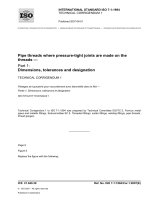
The elements of a typical pressure-based measurement system for determining liquid content (height) are
shown schematically in Figure 1. These include the tank, its bubbler probes, its temperature probes and the
manometer(s) used to measure pressure. Figure 1 also gives the nomenclature that is used throughout the six
parts of ISO 18213.
The bubbling pressure depends not only on the height of the liquid above the tip of the dip tube, but also on
the pressure in the tank at the liquid surface. What is measured in practice is the difference between the
pressure of the gas in the major (or minor) probe and the pressure of gas in the reference probe.
In the configuration shown in Figure 1, the major (minor) probe is connected at the high-pressure side of the
manometer and the reference probe is connected at the low-pressure side. This configuration, although typical,
is not the only one possible. In another widely-used configuration, for example, the major probe is connected
at the high-pressure side of the manometer while the minor and reference probes are connected at the
low-pressure side. Minor modifications in the methods and nomenclature of this part of ISO 18213 can be
required when these methods are applied to configurations differing from that shown in Figure 1.2)
2) The advantage of the configuration shown in Figure 1 is that, once the minor probe is submerged, it yields duplicate
measures of liquid height. The alternative configuration yields one measure of liquid height and a measure of the
difference in pressure between the major and minor probes.
3
© ISO 2007 – All rights reserved
Copyright International Organization for Standardization
Provided by IHS under license with ISO
No reproduction or networking permitted without license from IHS
Not for Resale
ISO 18213-1:2007(E)
--`,,```,,,,````-`-`,,`,,`,`,,`---
Key
1
2
manometer
gas supply (N2 or air)
3
flowmeters
Probe
Major probe
Minor probe
Reference probe
P1
P2
Pr
r1 (primary)
r2 (secondary)
—
Height of the liquid above the
reference point
H1
H2
—
Elevation of the pressure
gauge (manometer) above the
reference point
E1
E2
Er
Elevation of the reference
probe above liquid surface
h = E1 − Er − H1
h = E2 − Er − H2
—
Elevation of reference point
above bottom of the tank
ε
ε+Sa
—
Probe designation
Reference point
a
Vertical distance (probe separation): S = H1 − H2.
Figure 1 — Elements of a typical pressure measurement system for determining liquid content
4
Copyright International Organization for Standardization
Provided by IHS under license with ISO
No reproduction or networking permitted without license from IHS
© ISO 2007 – All rights reserved
Not for Resale
ISO 18213-1:2007(E)
4.2.2
Tank
The tank in which liquid height is measured should be equipped with at least two tubes (probes) of small
diameter (< 15 mm). One of the probes (the major probe) should extend as close to the bottom of the tank as
possible (without touching it). This probe should be rigidly mounted so that its position relative to the tank is
fixed and it is not in contact with any point on the wall of the tank. The second probe (reference probe) shall
also extend into the tank, but it should be as short as possible (or mounted on the vent pipe), so that its tip is
above the maximum filling level.
Each probe should be connected to two rigid tubes (pipes) of small diameter, one of which is connected to a
gas supply and one of which is connected to a pressure gauge (manometer). The two tubes for each probe
should be of the same diameter and as close to the same length as possible (and preferably co-located). The
tubes should be installed (mounted) so that they are not subject to vibrations that can adversely affect the
measurement quality.
Changes in temperature can significantly affect the reliability of data for calibration and volume determination,
especially through their effect on liquid density. Therefore, the tank should be equipped with temperature
probes that are calibrated to ensure measurements with an accuracy of at least 0,5 °C.
The tank shall also be equipped with instrumentation (spargers, agitators, etc.) to ensure that its contents are
homogeneous and at uniform temperature at the time of measurement. These instruments shall be capable of
operating at rates that maintain the homogeneity and uniformity of the liquid without causing excessive motion
or evaporation during a calibration run. It shall be possible to turn these instruments off on demand to make
the necessary measurements.
To ensure stable measurement conditions, the tank, together with its operating and measurement systems,
should be isolated insofar as possible from other elements (e.g. surrounding tanks) of the plant process.
4.2.3
Manometers
--`,,```,,,,````-`-`,,`,,`,`,,`---
Tanks equipped with pressure measurement systems for determining liquid content shall also be equipped
with manometers for measuring the pressure of the bubbling gas flowing through the probe lines. The selected
manometer(s) should be equipped with a digital readout or connected to a digital voltmeter so it/they can be
interfaced electronically with other components of the tank measurement and calibration systems.
The manometer system shall be sensitive enough to measure pressure with sufficient precision to meet
safeguard requirements imposed on the tank. If it is necessary, for example, to resolve 1-l volumes, this in
turn imposes a requirement on manometer resolution (see 6.3.3). Generally, a manometer system that can
resolve pressure differences of 1 Pa to 2 Pa or less is suitable for safeguards purposes. The manometer
system should also have a differential range that is appropriate for its intended use. While a manometer with a
differential range of 50 000 Pa can be required for a large input tank, one with a narrower range of 20 000 Pa
can be suitable for a smaller output tank.
The electronic acquisition and transfer of data is important both for eliminating data recording errors and for
ease of operation, especially during calibration exercises (see 4.5). The system should be capable of
measuring continuously, or with a frequency of at least 5 Hz.
4.2.4
Bubbling gas
A supply of gas is required. The supply shall be sufficient, not only to maintain flow in the reference probe that
vents into the tank above the liquid surface, but also to maintain bubbling at the tip of the submerged probe(s)
throughout the established measurement periods. Instrumentation for delivering and controlling the flow of gas
through the probe lines shall be capable of maintaining a constant flow rate during calibration and
measurement activities. The delivery system should allow the gas to reach thermal equilibrium within the
facility so that large thermal gradients are avoided.
The selected bubbling gas shall be inert with respect to the calibration and process liquids. Moreover, a gas
should be selected whose physical properties (especially density) are well known so that necessary
standardization calculations can be carried out (see ISO 18213-4 or ISO 18213-5). Compressed air and
5
© ISO 2007 – All rights reserved
Copyright International Organization for Standardization
Provided by IHS under license with ISO
No reproduction or networking permitted without license from IHS
Not for Resale
ISO 18213-1:2007(E)
nitrogen are widely used in practice. Nitrogen is easy to use. Compressed air, on the other hand, has the
advantage that many of the data-standardization calculations are somewhat simpler (see ISO 18213-2),
provided that air is compatible with the process. When selecting a bubbling gas, it is useful to consider that dry
air has the tendency to increase evaporation, whereas saturated (wet) air has the tendency to increase
condensation.
With fast bubbling rates, flow rates between 6 l/h and 20 l/h are typically used during measurement periods.
The optimal flow rate depends on the diameter of the dip tube: greater flow rates are required for dip tubes of
larger diameter. A mass flow meter whose set point can be fixed at 0,1 l/h is required for making
measurements at slow bubbling rates (see ISO 18213-4:—, Annex C).
4.2.5
Ambient conditions
Measurements for tank calibration and volume determination are sensitive to changes in ambient conditions.
Therefore instrumentation is required to measure ambient temperature, barometric pressure and relative
humidity. Data on ambient conditions are required to standardize a series of measurements to a fixed set of
reference conditions (see ISO 18213-2).
4.3
Prover system
One of two basic prover systems, gravimetric or volumetric, may be employed to make independent
measurements of the liquid added to the tank via the calibration process. A gravimetric prover, which is
essentially a container on a scale, provides a measure of the mass of liquid added to the tank. A volumetric
prover system consists of one or more containers of differing capacity, each of which has been fabricated to
deliver a single fixed volume of liquid at some predefined temperature. A combined gravimetric-volumetric
prover system (essentially a volumetric prover on a scale) may be employed to provide a redundant
measurement capability. Gravimetric systems are more widely used in practice, but it is possible to obtain high
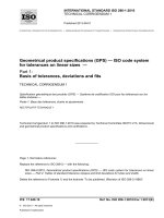
quality calibration measurements with either system. A typical tank calibration setup is shown schematically in
Figure 2.
Several considerations enter into the selection of a suitable prover system for tank calibration. The prover
system shall not only be capable of delivering calibration increments in sizes that are consistent with the
capability of the tank’s measurement system, but it shall also deliver increments that meet other accountability
requirements and procedural constraints.
Increment size(s) should be large enough to affect a change that is at least five times the resolution of the
tank’s measurement system (see 6.3.3), but small enough to permit adequate resolution of important
structural features in the tank (see 6.6.3).
Subject to this system resolution constraint, it is generally desirable to plan for as many calibration increments
as time and resources allow. For larger tanks, the total time required for a calibration run can become a
consideration. The selected prover system should be designed to fill and empty rapidly enough to deliver a
sufficient number of increments (at least 50 and preferably more) to obtain the required resolution within
approximately 12 h (see 5.2).
To meet resolution and time constraints, it can be necessary to use increments of several sizes during a
calibration run. For this purpose, it is possible to construct a volumetric prover system that delivers a range of
increment sizes by fabricating several different-sized containers, each of which delivers a single, fixed volume
of liquid. However, the change from one container to another can be time-consuming, especially if it is
necessary to disconnect and reconnect drain lines. Moreover, if it is necessary to move calibration containers,
they shall be leveled after each move. These inconveniences can be circumvented with a gravimetric prover
which, being essentially a container on a scale, can deliver a continuous range of volume increment sizes.
Another advantage of a gravimetric prover is that it is possible to make multiple readings for each
measurement. On the other hand, a gravimetric prover is sensitive to environmental conditions (e.g. air
currents) and requires two measurements for each calibration increment (e.g. the mass of the container
before and after the increment is delivered to the tank). Regardless of which type of prover system is selected,
however, the decision to use several increment sizes during a calibration should be made with care because
statistical analysis of the data can be more difficult when different-sized calibration increments are used.
--`,,```,,,,````-`-`,,`,,`,`,,`---
6
Copyright International
Organization for Standardization
Provided by IHS under license with ISO
No reproduction or networking permitted without license from IHS
© ISO 2007 – All rights reserved
Not for Resale
ISO 18213-1:2007(E)
--`,,```,,,,````-`-`,,`,,`,`,,`---
Key
1
liquid temperature probe(s)
2
3
process lines (vent, fill, empty, decontamination, sparge, sample, etc.)
supply-line calibration liquid
4
5
callibration liquid supply
prover vessel
6
7
scale
purge gas supply
8
9
differential pressure manometers
tank internals (coils, braces, agitator, etc.)
10 isolation barrier
P1 major probe
P2 minor probe
Pr reference probe
a
b
Level 2 (“density”)
Level 1 (“level”).
Figure 2 — Elements of a typical tank calibration setup
7
© ISO 2007 – All rights reserved
Copyright International Organization for Standardization
Provided by IHS under license with ISO
No reproduction or networking permitted without license from IHS
Not for Resale
ISO 18213-1:2007(E)
4.4
Calibration liquid
A supply of calibration liquid sufficient to complete a planned calibration exercise, which can consist of several
calibration runs, is required. It is desirable to move the liquid into the facility far enough in advance of the
calibration exercise for its temperature to equilibrate with that of its surroundings.
Factors that should be considered when selecting a calibration liquid are discussed in 6.5.4.
4.5
Calibration software
It is strongly recommended that the tank calibration and volume measurement systems be connected to a
computer that controls the operation of the calibration process and processes the acquired data. A
computerized system can help to simplify the calibration procedure, improve the consistency with which it is
carried out and substantially reduce the work involved in performing a calibration exercise. At a minimum, a
computer should be used for acquiring the data from the tank’s measurement instruments (manometers) and
transferring it to a suitable data base for analysis. The ability to acquire and transfer calibration data
electronically eliminates the possibility of transcription errors and reduces the effort required for data
verification, especially if it is necessary to assemble the calibration data set from data collected at several
reading stations. The development of a program that can control the entire calibration operation, acquire and
record the required data, perform the necessary data standardization operations, and provide on-line checks
of data validity is strongly recommended.
--`,,```,,,,````-`-`,,`,,`,`,,`---
Calibration software should be capable of accepting multiple instrument readings for each calibration
measurement (see 6.6.4). This capability is particularly important for instruments that measure the primary
calibration variables, such as manometers (that measure pressure) and scales (that measure mass). With
multiple measurements, the effect of one or two erroneous readings can be minimized or eliminated.
Moreover, replicate measurements are required to estimate the statistical properties of the measurement
process. Although it is helpful to compute summary statistics (e.g. average and standard deviation) for each
set of multiple readings at the time they are made, it is advisable to archive all individual readings for
subsequent detailed analysis. All measurements are sensitive to temperature variations, so the software
should be capable of recording the temperature of the relevant liquid in both the tank and the prover for each
calibration measurement. Finally, the software should be capable of recording and archiving information on
ambient conditions, such as temperature, barometric pressure and relative humidity (see 6.6.2).
It is recommended that the data standardization calculations (see especially ISO 18213-2, ISO 18213-4, and
ISO 18213-5) be done as the data are acquired. This practice is not only convenient, but also helps to provide
procedural consistency. Moreover, comparisons involving data collected under varying measurement
conditions are more reliable if the data are standardized to a fixed set of reference conditions before the
comparison is made. Although special-purpose software has been developed for data standardization, all of
the calculations indicated in ISO 18213-2, ISO 18213-4, ISO 18213-5, and ISO 18213-6 can be done with the
aid of commercially available software.
With more advanced special-purpose calibration software, procedures can and should be established for
routinely checking the validity of the data collected for each volume increment as they are acquired. Such
validation procedures should, for example, ensure that the prover is filling and draining properly. A variety of
interrelated consistency checks involving liquid height and volume measurements can be devised for a
particular calibration system. These checks serve to identify erroneous readings and can provide an early
indication of possible instrument malfunctions.
5
5.1
A typical tank calibration procedure
Calibration procedure
With adequate preparation, the procedural steps involved in conducting a tank calibration run are relatively
straightforward. A tank may be calibrated either by making incremental additions of liquid to it or by making
incremental removals of liquid from it. Both methods are equally valid. However, for the sake of clarity and
because the practice is more common, it is assumed that calibration is done by means of incremental
8
Copyright International Organization for Standardization
Provided by IHS under license with ISO
No reproduction or networking permitted without license from IHS
© ISO 2007 – All rights reserved
Not for Resale
ISO 18213-1:2007(E)
additions. Under this assumption, a calibration run involves making a series of additions of carefully measured
quantities of calibration liquid to the tank and, after each addition, recording the measurement system
response, the temperature of the liquid in the tank and current ambient conditions (or changes therein). As
indicated in 4.5, appropriate data standardization calculations may be performed in connection with each
increment at the time of acquisition.
The following steps are carried out during a typical calibration run.
--`,,```,,,,````-`-`,,`,,`,`,,`---
a)
Preparatory steps are carried out. These include isolating, flushing, and drying the tank, and performing a
pre-calibration leak test of the pneumatic systems.
b)
Initial steps are completed. These include such activities as making a final system check, zeroing
measurement instruments, and recording data on reference and ambient conditions.
c)
The prover is filled with calibration liquid.
d)
Prover-related data are recorded as specified in the calibration protocol (see Clause 4 and 6.7). For a
gravimetric prover system, the before-delivery mass of the prover and calibration increment is required.
For a volumetric prover, the volume and the temperature of each calibration increment are required (see
Clause 4 and 6.5). Ambient conditions or changes therein are also recorded.
e)
The liquid is transferred from the prover to the tank and sufficient time is allowed for drainage (see
procedural notes in 5.2 below). For a gravimetric prover system, the after-delivery mass of the prover is
recorded.
f)
Sufficient time is allowed for conditions in the tank to stabilize. Steps, such as mixing and waiting for the
release of trapped gas, are taken to ensure that the liquid in the tank is homogeneous and free of
significant thermal gradients. After mixing, sufficient time is allowed for the liquid level to reach static
equilibrium (see 5.2 below).
g)
Measurements required to determine tank content are made. The response of the tank’s measurement
system, the temperature of tank liquid, and other information required to clarify or interpret these data are
recorded.
h)
Steps 3 to 7 are repeated for each calibration increment specified in the calibration plan (see 6.7).
Typically, the increments are designed to calibrate the entire tank or a particular region of interest. The
region of interest and the sizes of the calibration increments are specified in a comprehensive calibration
plan.
i)
Closing verification and confirmatory steps such as leak tests (see 6.3.5) are conducted.
A tank calibration exercise typically consists of several calibration runs. A single run can be sufficient to verify
an existing calibration or volume measurement equation.
If the tank cannot be completely emptied and dried between calibration runs, it can be necessary to determine
its heel volume prior to the start of the calibration exercise (see Clause 3 and ISO 18213-2:2007, Annex C).
5.2
Procedural notes
The various waiting times (between increments, after mixing, etc.) encountered during the calibration process
depend on factors that are specific to a particular tank, its operating systems, and the selected calibration
system. In preparation for the calibration exercise, appropriate waiting times should be determined
experimentally within each facility, and suitable measurement stability criteria should be incorporated into the
calibration software.
Excessive mixing and waiting times should generally be avoided to minimize evaporation losses, changes in
measurement conditions, and the effects of condensation.
9
© ISO 2007 – All rights reserved
Copyright International Organization for Standardization
Provided by IHS under license with ISO
No reproduction or networking permitted without license from IHS
Not for Resale
ISO 18213-1:2007(E)
A calibration run should continue to completion without major interruptions or time delays after it has been
started. Calibration runs of more than 12 h should generally be avoided unless special precautions are taken
to minimize the effects of evaporation and changes in ambient conditions.
The key to a successful calibration exercise is a complete and comprehensive calibration plan. Items that
should be addressed in a comprehensive calibration plan are discussed in Clause 6.
6
6.1
Calibration planning and pre-calibration activities
The calibration plan
--`,,```,,,,````-`-`,,`,,`,`,,`---
The goal of the calibration exercise is to obtain a high-quality set of data that can be used to estimate a tank’s
calibration or volume measurement equation, together with the necessary ancillary data to analyze and
interpret these calibration data. Thorough planning is crucial to the achievement of this goal and its
importance cannot be over-emphasized. The calibration planning effort should culminate in a detailed written
calibration protocol (calibration plan) that specifies both the procedural details for the calibration steps of the
previous section and the conditions under which they are carried out. Careful planning, as reflected in the
calibration protocol, establishes a context in which the required measurement accuracy for the calibration (or
volume measurement) equation can be weighed against the effort devoted to the calibration exercise.
A comprehensive calibration planning exercise should include each of the following:
⎯
assessment of the required measurement accuracy and a preliminary error analysis;
⎯
review of the tank and its measurement (manometer) and support systems;
⎯
preparations for calibration of the tank calibration equipment (prover system);
⎯
specification of reference operating conditions under which calibration measurements [e.g. pressure
(tank) and mass (prover)] are to be made;
⎯
preparations and plans for the acquisition, verification and subsequent detailed analysis of calibration
data.
Finally, the calibration plans should culminate in a pour schedule that specifies the number and size of the
calibration increments to be made during each calibration run.
In addition to the items specifically listed above, the calibration plan should address any other factors that are
specific to the particular calibration exercise being planned. In short, the planning exercise should result in a
thorough understanding of the tank, its measurement and support systems, the calibration equipment and the
relationships among them. This understanding is the basis for a smooth calibration exercise.
6.2
Measurement requirements and preliminary error analysis
A clear statement of the required volume measurement accuracy should be developed for the tank. The
maximum acceptable error limits for volume determinations should take account of the tank’s role in the
overall accountability plan for the facility, a major consideration being the amount of nuclear material involved.
For primary accountability tanks, relative standard deviations as small as 0,1 % or less may be prescribed for
individual volume determinations. Such limits are achievable with state-of-the-art measurement systems
operated under favourable conditions. Of course, if specified error limits subsequently prove to be inconsistent
with system capability, some corrective action (e.g. upgrading the measurement system or relaxing
measurement requirements) can be required.
10
Copyright International Organization for Standardization
Provided by IHS under license with ISO
No reproduction or networking permitted without license from IHS
© ISO 2007 – All rights reserved
Not for Resale
ISO 18213-1:2007(E)
A preliminary error analysis should be performed after a review of the tank and the calibration system. This
analysis is an item-by-item assessment of measurement uncertainty for the components of the volumemeasurement-and-tank-calibration process.3) This preliminary error analysis is intended to identify possible
inconsistencies between measurement capability and required measurement accuracy. The analysis should
also help to identify any system components or procedural steps that require special attention because they
are particularly vulnerable to error. Whenever possible, uncertainty estimates should be based on in-plant
observations that reflect actual operating conditions, rather than upon manufacturer’s specifications or other
“standard” estimates. The choice of an appropriate statistical model will depend on the relative magnitudes of
uncertainties associated with specific error sources.
6.3
The tank and its measurement support systems
6.3.1
Engineering review
Personnel responsible for tank calibration should perform an engineering review of the tank to become familiar
with its construction and installation; its physical environment; and the operation of its measurement, transfer,
and support systems. The entire measurement domain of the tank, which includes all operating and support
systems that can affect measurement system response, should be evaluated during the engineering review.
Plans should also be made at this time for isolating the tank during the calibration exercise.
6.3.2
Equipment checkout
The integrity of the tank, its process and instrument lines, and all calibration equipment should be verified prior
to the calibration exercise. A checklist should be compiled to ensure that necessary preliminary operation
steps (e.g. flushing the tank to be calibrated and isolating it from adjacent tanks) are performed prior to the
start of a calibration exercise and that all normally active auxiliary systems (off-gas service, bubbler air flow,
etc.) are operational and operated according to standard procedures during the calibration. The availability of
suitable connections to the tank should be checked, and steps should be taken to ensure that temperatures
will be reasonably stable during calibration.
Transfer procedures should be reviewed to identify possible points of hold-up in sparge, sampling and cold
chemical lines. If possible, all hold-up should be eliminated, especially in transfer lines used for calibration.
Otherwise, plans should be made to estimate the volume of liquid at hold-up points or to otherwise control the
effect of hold-up on liquid height and volume determinations (see 6.4.3).
6.3.3
Measurement system resolution
The resolution of the tank’s measurement (manometer) system is required not only for the preliminary error
analysis, but also to establish a lower limit for the size (volume) of a calibration increment. The product of the
measurement system resolution and the cross-sectional area of the tank gives the detection threshold
(minimal detectable volume) for the tank and its measurement system. The size of minimum calibration
increment should, in turn, be at least five times the detection threshold (see 4.3). For example, in a tank with a
cross-sectional area of 2 m2 and a measurement system capable of resolving a 0,5 mm column of water
(approximately 5 Pa), the detection threshold is approximately 1 l, so the volume of a calibration increment (of
water) should be at least 5 l.
6.3.4
Tank profile
Potential transition regions (regions of the tank in which the cross-sectional area changes rapidly with height)
should be identified during the engineering review because they can require special attention during a
calibration run. Knowledge of transition regions is also helpful for developing the tank’s calibration or volume
measurement equation because calibration segments are determined largely by examining the tank’s profile
to identify transition regions. The locations of any protrusions and internal equipment are especially helpful
and can be obtained from “as-built” engineering drawings of the tank. These points can require special
treatment (e.g. smaller calibration increments) during the calibration and they can also serve as reference
3)
See ISO 18213-3:—, Annex C, for guidance in conducting a preliminary error analysis.
--`,,```,,,,````-`-`,,`,,`,`,,`---
© ISO 2007 – All rights reserved
Copyright International Organization for Standardization
Provided by IHS under license with ISO
No reproduction or networking permitted without license from IHS
Not for Resale
11
ISO 18213-1:2007(E)
points for aligning the data from several runs. Alignment is necessary if the tank cannot be completely emptied
because successive calibration runs begin at an unknown level that varies from run to run (see
ISO 18213-2:2007, Annex D).
6.3.5
Leaks
All leaks shall be eliminated from pneumatic lines, the transfer and sparging systems and the tank itself prior
to the start of a calibration run. The effect of the leaks cannot be adequately quantified, so all calibration data
acquired when detectable leaks are present shall be declared invalid and discarded. Therefore, a leak test
should be performed (i) before each calibration run to verify that leaks are not initially present and (ii) after
each run to verify that calibration data have not been invalidated by leaks which appeared during the run.
Pneumatic lines can easily be checked for air leaks without transferring liquid simply by turning off the air flow
to the probes and observing whether the pressure readings remain constant.
Specifically, the following procedure can be used to check for leaks in pneumatic lines at the start of a
calibration run. First, the tank is emptied (if it is not already empty). Next, the air flow meters are balanced and
enough liquid is added to the tank to cover normally submerged probes. Then, the air to the probes is turned
off and the observed pressures are recorded. A leak is indicated if the readings do not remain constant
throughout a time period of 15 min to 20 min or more.
Similarly, leaks can be detected at the end of a calibration run by observing pressures for the nearly filled tank
for an extended period of time. Instruments such as the air sparge and the recirculating sampler should be
activated in accordance with established operating procedures during the observation period. However,
extended operation of the tank’s sparging, off-gas, and sampling systems should be avoided during leak
testing because these practices can also cause a decrease in pressure (primarily due to evaporation losses).
Any unexpected changes in pressure during this test indicate the presence of leaks. If several calibration runs
are planned in succession, it can be procedurally convenient to take the leak test at the end of one run as the
initial leak test for the next run.
Leak tests are not conclusive unless the tank’s pneumatic systems can be isolated from other plant systems
and activities. Moreover, when a leak is indicated, the leak test cannot distinguish the source of the leak.
Additional testing can be required to find a particular leak because leaks in the tank, in its operating systems,
and in pneumatic lines all produce a decrease in pressure.
6.3.6
Instrument calibration
Instruments used to measure volume, pressure, temperature, and related ancillary variables should either be
in calibration at the time of a tank calibration exercise or be calibrated prior to its start. In planning for the
calibration of these instruments, the manufacturer’s manuals and required equipment should be procured as
necessary.
6.4
6.4.1
Calibration equipment (prover system)
Equipment review
--`,,```,,,,````-`-`,,`,,`,`,,`---
In preparation for a calibration exercise, personnel should become familiar with the prover system. Personnel
should also become familiar with existing equipment for calibrating provers or make plans to acquire new
calibration equipment, as appropriate.
6.4.2
Prover calibration
If the prover system is not in calibration at the time of the planned tank calibration exercise, arrangements
should be made to calibrate it prior to the start of the exercise. For a gravimetric prover, this involves
calibrating the scale(s) used to measure volume increments. Calibration of a volumetric prover involves
making a very precise determination of its contained volume at some reference temperature. A facility may
choose to calibrate its own provers, or to engage a recognized outside agency (e.g. a state or federal bureau
of weights and measures). Either alternative is acceptable, provided that recognized calibration procedures
are used and valid measures of uncertainty are given for the values assigned to test measures. Typically, a
12
Copyright International Organization for Standardization
Provided by IHS under license with ISO
No reproduction or networking permitted without license from IHS
© ISO 2007 – All rights reserved
Not for Resale
ISO 18213-1:2007(E)
scale calibration is done on-site by the appropriate instrument group at the facility and a volumetric prover is
calibrated off-site by a recognized state or national authority.
For in-house calibrations, only test weights and instruments whose calibration and uncertainty values are
traceable to suitable national or international standards should be used. These weights and instruments
should be calibrated prior to their use for prover calibration and all certifications should be valid at the time the
instruments are used. All weighings made for calibration should be corrected for the effect of air buoyancy
(see ISO 18213-2:2007, Annex B).
Calibration procedures should be reviewed to ensure that they are compatible with the method to be used for
transferring calibration liquid to (or from) the tank. For example, to calibrate a tank by means of incremental
additions, the prover should be calibrated for the volume it delivers. Regardless of the decision to calibrate
scales and provers in-house or elsewhere, a schedule should be established that allows ample lead time.
6.4.3
Location of equipment
The prover should be located as close to the tank as possible and should be maintained in a level position. All
calibration equipment should be located where it will not be moved or disturbed during a calibration exercise,
and should be installed so that it is free of vibrations and electronic interference. Lines used to introduce
calibration liquid into the tank should be completely free of the prover and should not come in contact with it.
Lines used to deliver calibration liquid from the prover to the tank should be arranged so that there is no liquid
holdup. If this is impossible, an initial increment to wet lines and fill holdup points should be considered. It is
highly desirable to jet excess liquid introduced by this “wetting” increment from the tank before the start of the
calibration run.
6.5
Reference operating conditions
6.5.1
General
To ensure the comparability of a series of calibration measurements, steps should be taken to ensure that
consistent operating procedures are maintained throughout the measurement period. Moreover, insofar as
possible, steps should be taken to ensure that measurements of process liquid are made under the same
conditions that prevail at the time of calibration (or vice versa). The goal is to minimize measurement
variability by standardizing operating procedures and minimizing variability in ambient conditions.
Factors that can affect measurement system response are identified in this clause. Suitable operating
procedures are discussed, and possible corrective actions are suggested to compensate for variations in
ambient conditions that cannot be controlled.
6.5.2
Operating variables
Procedures should be established to ensure that standard settings on all operating and support systems are
maintained throughout the calibration process. The same settings used for calibration should subsequently be
used for measurements made to determine process liquid volumes. Operational factors that can affect
measurement system response include the gas purge (flow) rate, off-gas vacuum, air sparge and the
elevation of the manometer above the tank.
6.5.2.1
Gas purge rate
Gas purge is the flow of gas (e.g. air) through the pneumatic lines. For fast bubbling rates, flow resistance can
cause back pressure in the lines that can bias measurement results. The back pressure depends upon the
purge (flow) rate and the length and diameter of the lines. To minimize the effect of flow resistance, all
accountability measurements should be made at a fixed flow rate. In particular, all measurements of pressure
for calibration or volume determination should be made at the same flow rate that is used during routine plant
operation.
--`,,```,,,,````-`-`,,`,,`,`,,`---
13
© ISO 2007 – All rights reserved
Copyright International Organization for Standardization
Provided by IHS under license with ISO
No reproduction or networking permitted without license from IHS
Not for Resale
ISO 18213-1:2007(E)
If pressure drop due to flow resistance is found to be significant, corrections can be calculated as indicated in
ISO 18213-5:—, Annex A. Corrections for flow resistance should be considered unless pneumatic lines are
sufficiently large (at least 5 mm or 0,25 in in diameter), the purge rate is relatively small (less than 20 l/h or
0,75 f3/h under standard conditions), and line configurations are identical for calibration and volume
measurements. Corrections should be made for tall tanks (4 m or more), especially if they are expected to
receive liquids (including the calibration liquid) that vary significantly in density (e.g. by more than 50 %).
Regardless of their importance for a particular situation, it is good practice to apply the corrections indicated in
ISO 18213-5 to all measurements as a matter of course.
6.5.2.2
Off-gas vacuum
Fluctuations in off-gas vacuum can cause anomalous or highly variable measurement system responses.
Therefore, pressure readings should be made only when the off-gas vacuum is stable. Vapour head
(reference) pressure should be established relative to an outside reference and monitored to ensure that
pumping operations in adjacent tanks do not affect pressure measurements.
6.5.2.3
Air sparge
The air sparge should be off when pressure readings are made to ensure that calibration measurements are
not excessively variable. If sparging is necessary, the air sparge should be operated for as short a time as
possible to minimize the loss of calibration liquid by evaporation. To minimize measurement times, it is
convenient to operate the sparge while calibration liquid is added to the tank.
6.5.2.4
Manometer elevation
The difference between the pressure at the tip of the probe and at the manometer depends not only on the
purge rate, but also on the mass of the purge gas in the line and the elevation of the manometer above the tip
of the probe. Manometers used to measure pressure for tank calibration or volume determination should be
kept at a constant elevation to minimize these effects.
Corrections that compensate for the mass of gas in the probe lines and differences in manometer elevation
are given in ISO 18213-4 or ISO 18213-5 for slow and fast bubbling rates, respectively. These corrections
should be made if the elevation of the manometer above the tip of the probe is large (e.g. greater than 1 m).
Regardless of the elevation difference in a particular situation, it is good practice to apply the corrections
indicated in ISO 18213-4 or ISO 18213-5 to all measurements as a matter of course.
6.5.3
Temperature
Temperature variations have a significant effect on measurement results because they affect nearly all
aspects of the measurement process. Temperature changes affect both the response of the tank’s
measurement system and the prover system. They affect the dimensions of the tank and, more importantly,
they affect the densities of all liquids involved in the tank calibration and volume determination process. The
combined effect of these changes can be quite complex.
Even moderate temperature changes can have a significant adverse effect on a series of calibration
measurements unless changes in liquid density are taken into account. For example, a change of 3 °C in the
temperature of water near 25 °C induces a change of nearly 0,1 % in its density. Failure to compensate for
this change directly affects the height calculations based on Equation 1. This effect is transmitted in turn to the
volume determinations made with the calibration (measurement) equation derived from these height
determinations. Therefore, it is important to use an accurate measure of the density of the liquid at the time it
was measured (i.e. at its measurement temperature) when calculating liquid height from pressure (see 6.5.4).
It can be difficult to maintain a constant temperature for a series of measurements and temperatures can differ
significantly between two measurement periods (e.g. between two calibration runs). Therefore, a pre-selected
reference temperature should be established and provision should be made to routinely adjust all
measurements of liquid content to this reference temperature. The statement applies equally to calibration
measurements and to measurements of process liquids made for accountability purposes. It is convenient to
select a reference temperature, such as 25 °C or 30 °C, that is close to the ambient temperature in the facility
or in the laboratory.
14
Copyright International Organization for Standardization
Provided by IHS under license with ISO
No reproduction or networking permitted without license from IHS
--`,,```,,,,````-`-`,,`,,`,`,,`---
Not for Resale
© ISO 2007 – All rights reserved