Astm f 326 96 (2012)
Bạn đang xem bản rút gọn của tài liệu. Xem và tải ngay bản đầy đủ của tài liệu tại đây (239.91 KB, 8 trang )
Designation: F326 − 96 (Reapproved 2012)
Standard Test Method for
Electronic Measurement for Hydrogen Embrittlement From
Cadmium-Electroplating Processes1
This standard is issued under the fixed designation F326; the number immediately following the designation indicates the year of original
adoption or, in the case of revision, the year of last revision. A number in parentheses indicates the year of last reapproval. A superscript
epsilon (´) indicates an editorial change since the last revision or reapproval.
3.2 Symbols:
3.2.1 HP = calibration hydrogen pressure peak.
3.2.2 HPp = plating hydrogen pressure peak.
3.2.3 IE = probe cathode emission current.
3.2.4 IH = probe hydrogen pressure.
3.2.5 Iγ = integral of I H curve from probe on to HP.
3.2.6 lambda = time in seconds for hydrogen pressure peak
to drop to half its value.
3.2.7 λ = lambda obtained from a calibration run.
3.2.8 λp = lambda obtained from a plating run.
3.2.9 λpc = normalized test lambda, obtained as follows:
1. Scope
1.1 This test method covers an electronic hydrogen detection instrument procedure for measurement of plating permeability to hydrogen. This method measures a variable related to
hydrogen absorbed by steel during plating and to the hydrogen
permeability of the plate during post plate baking. A specific
application of this method is controlling cadmium-plating
processes in which the plate porosity relative to hydrogen is
critical, such as cadmium on high-strength steel.
1.2 This standard does not purport to address all of the
safety concerns, if any, associated with its use. It is the
responsibility of the user of this standard to establish appropriate safety and health practices and determine the applicability of regulatory limitations prior to use. For specific hazard
statement, see Section 8.
1.3 The values stated in SI units are to be regarded as the
standard. The values given in parentheses are for information
only.
λ pc 5 λ p ~ 40/λ !
(1)
3.2.10 λ¯ pc = arithmetic average of normalized lambdas for a
set of tests.
3.2.11 range = difference between maximum λpc and minimum λpc for a given set of tests.
3.2.12 run = calibration or plating of a probe.
3.2.13 test = single evaluation of a plating solution for
hydrogen embrittlement determination; run using a previously
calibrated probe.
3.2.14 set of tests—all consecutive tests on a plating solution for a given operator-instrument-day evaluation.
2. Referenced Documents
2.1 ASTM Standards:2
D1193 Specification for Reagent Water
F519 Test Method for Mechanical Hydrogen Embrittlement
Evaluation of Plating/Coating Processes and Service Environments
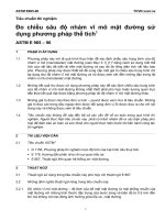
3.2.15 window—test surface of a probe described in Fig.
1(A).
3. Terminology
3.1 Definitions of Terms Specific to This Standard:
3.1.1 hydrogen pressure peak—the maximum hydrogen
pressure value (see IH) obtained when the probe is heated
following calibration, plating, or fluid testing.
4. Summary of Test Method
4.1 This method uses a metal-shelled vacuum probe as an
ion gage to evaluate electrodeposited cadmium characteristics
relative to hydrogen permeation. After calibration, a section of
the probe shell is electroplated at the lowest current density
encountered in the cadmium electroplating process. During the
subsequent baking of the probe at a closely controlled
temperature, the probe ion current, proportional to hydrogen
pressure, is recorded as a function of time. From these data and
the calibration data of the probe, a number related to the
porosity of the electroplated metal relative to hydrogen is
obtained.
1
This test method is under the jurisdiction of ASTM Committee F07 on
Aerospace and Aircraft and is the direct responsibility of Subcommitteee F07.04 on
Hydrogen Embrittlement.
Current edition approved Nov. 1, 2012. Published November 2012. Originally
approved in 1978. Last previous edition approved in 2006 as F326 – 96 (2006).
DOI: 10.1520/F0326-96R12.
2
For referenced ASTM standards, visit the ASTM website, www.astm.org, or
contact ASTM Customer Service at For Annual Book of ASTM
Standards volume information, refer to the standard’s Document Summary page on
the ASTM website.
4.2 During the initial part of the bakeout, hydrogen continues to diffuse through the metal shell of the probe and the ion
Copyright © ASTM International, 100 Barr Harbor Drive, PO Box C700, West Conshohocken, PA 19428-2959. United States
1
F326 − 96 (2012)
FIG. 1 Probe Configuration
6.2 Oven—The oven warms the probe to increase the
hydrogen diffusion rate into the probe. Oven parameters are
selected by apparatus manufacturer to provide a standard
reading for all hydrogen detection instruments.
current increases. Within a short time, however, a maximum
current is observed and then falls off as hydrogen is driven out
of the system.
4.3 Observations of the ion current-time curve indicate that
the slope of the curve has an empirical relationship with failure
data on stress rupture specimens such as those in Test Method
F519. For this method, Iγ and λ variables (see Section 3) must
be empirically correlated with results from the stress rupture
specimens. This gives a quick means of measuring ease of
baking hydrogen out of cadmium-electroplated parts.
6.3 Oven Stopper—Stopper covering the oven opening.
Remove 10 s before inserting the probe.
6.4 Window—The window is the unpainted, bare steel
portion of the probe, 0.63 6 0.03 in. in height, that is plated in
the solution under test. The window is shown in Fig. 1.
6.5 Abrasive Blast—Abrasive blast window area in the same
way, using the same media, as used for the parts. Probe should
be rotated while being blasted to provide uniform surface.
4.4 Before an electroplating test, calibration is accomplished by electrolyzing the probe in a standard solution and
baking it to determine Iγ and λ of the unplated steel shell of the
probe.
6.6 Electronic Bakeout Unit—This heats the probe electrically to remove hydrogen absorbed into the probe after testing.
May be part of hydrogen detection instrument.
5. Significance and Use
5.1 Hydrogen is evolved during metal electrodeposition in
aqueous baths. Some of this hydrogen enters parts during
plating. If the absorbed hydrogen is at a level presenting
embrittlement hazards to high-strength steel, it is removed by
baking parts after plating to expel this hydrogen. However, the
lack of plate porosity itself may block hydrogen egress. Thus,
it becomes important to know both the relative amount of
hydrogen absorbed and the plate porosity.
7. Reagents and Materials
7.1 Reagents:
7.1.1 Purity of Reagents—Reagent grade chemicals shall be
used in all tests. Unless otherwise indicated, it is intended that
all reagents conform to the specifications of the Committee on
Analytical Reagents of the American Chemical Society where
such specifications are available.3 Other grades may be used,
provided it is first ascertained that the reagent is of sufficient
high purity to permit its use without lessening the accuracy of
the determination.
7.1.2 Acetone (C3H6O), technical.
7.1.3 Anode Cleaning Solution—Concentrated nitric acid
(HNO3), reagent grade.
7.1.4 Cadmium Stripping Solution—Ammonium Nitrate
(125 g/L)—Dissolve 125 g of ammonium nitrate (NH4NO3,
technical) in water and dilute to 1 L. Use at room temperature.
7.1.5 Calibration Solution—Sodium Cyanide (50 g/L) Plus
Sodium Hydroxide (50 g/L)—Dissolve 50 g of sodium hydroxide (NaOH) in water. Add 50 g of sodium cyanide (NaCN) and
dissolve. Dilute to 1 L. Use at 18 to 27°C (65 to 80°F).
5.2 This test provides a quantitative control number for
cadmium plate porosity that can be used to control a cadmium
plating process and the status of cadmium-plated hardware. It
can also be used for plating process troubleshooting and
research and development to determine the effects on plate
porosity by process variables, contaminants, and materials.
When used to control a critical process, control numbers for
plate porosity must be determined by correlation with stress
rupture specimens or other acceptable standards.
5.3 There is no prime standard for plate porosity. For this
reason, two ovens must be used, with tests alternated between
ovens. Data from the ovens are compared to ensure no
equipment change has occurred.
3
Reagent Chemicals, American Chemical Society Specifications, American
Chemical Society, Washington, DC. For suggestions on the testing of reagents not
listed by the American Chemical Society, see Analar Standards for Laboratory
Chemicals, BDH Ltd., Poole, Dorset, U.K., and the United States Pharmacopeia
and National Formulary, U.S. Pharmacopeial Convention, Inc. (USPC), Rockville,
MD.
6. Apparatus
6.1 Hydrogen Detection Instrument—A system consisting of
a control unit, two special ovens, auxiliary heater, recorder, test
probes, and associated equipment.
2
F326 − 96 (2012)
λ¯ pc (A) be the higher value and λ¯ pc (B) the lower value. Where
λ¯ pc (A) − λ¯ pc (B) is less than ∆, the ovens are comparable.
Where λ¯ pc (A) − λ¯ pc (B) is greater than ∆, the ovens are not
comparable.
7.1.6 Water, Distilled or Deionized, minimum electrical
resistivity 50 000 Ω·cm (for example, Specification D1193).
7.2 Materials:
7.2.1 Anodes (Calibration), solid-carbon arc rods, 5.1- to
12.7-mm (0.20- to 0.50-in.) diameter.
7.2.2 Anodes (Plating), cadmium rods, A-A-51126 6.4 to
12.7 mm (0.25 to 0.50 in.) thick, round or square.
7.2.3 Polytetrafluoroethylene (PTFE) Tape—The tape
should be appropriate for use in solution, width about 12 to 19
mm, thickness small enough to seal.
7.2.4 Glass 1-L Beaker.
12. Procedure
12.1 Bakeout of Probe:
12.1.1 Strip cadmium-plated probes in stripping solution
(7.1.4) and rinse in 50°C (122°F) water for 2 min before
bakeout.
12.1.2 Insert a probe into the socket of an electronic bakeout
unit.
12.1.3 Within 30 s, the heater should stabilize or be adjusted
to 86.5 6 16.5 mA. If the heater does not register current, the
probe is defective and must be discarded.
12.1.4 Bake out the probe for the time required to meet the
limits in 12.2. Do not continuously bake out probes for longer
than 2 h to preclude damaging paint.
8. Hazards
8.1 Sodium cyanide, cyanide, cadmium, nitric acid, and
acetone can be health hazards. Use adequate face, hands, and
respiratory protection commensurate with standards established by American Conference of Government and Industrial
Hygiene for these chemicals.
12.2 Probe Checkout—Probes that are new, or have been
calibrated or plated and stripped, need to be baked out to meet
checkout requirements as follows:
12.2.1 Hot Probe:
12.2.1.1 Set the range to 10.
9. Sampling
9.1 Stir plating bath to ensure homogeneity. The plating
bath sample must be representative of the bath. Obtain the
sample from beneath the surface of the bath, not by skimming
the surface. Chemical constituents must be within normal
operating range.
NOTE 1—Here and throughout the specification, range settings are for
full-scale reading.
10. Preparation of Apparatus
12.2.1.2 Remove the probe from the electronic bakeout unit;
plug into the socket assembly and 15 6 1 s after removal from
the bakeout unit, turn the probe on.
12.2.1.3 Observe the peak value of IH. If less than 1,
proceed with surface activation. If it is greater than 1.0, screw
on the cap and insert probe into the oven.
12.2.1.4 If I H is 0.5 or less within 5 min of inserting the
probe into the oven, proceed to surface preparation. If the
probe does not drop to IH = 0.5 or less with 5 min, bake out
again. If three successive bakeouts do not reduce IH to 0.5 or
less within 5 min of insertion into the oven, discard the probe.
12.2.1.5 Set the instrument to read I E. Probe IE should read
6.0 6 0.2 mA. If IE does not read or cannot be adjusted to this,
the probe or the instrument is defective. Check the instrument
with other probes to determine which is defective. Discard
defective probes.
12.2.2 Cold Probe:
12.2.2.1 Set the range to 1.0.
12.2.2.2 Plug the probe into socket assembly and turn on.
12.2.2.3 Observe the peak value of IH. If less than 0.2,
proceed to surface preparation. If greater than 0.2, insert into
the oven.
12.2.2.4 Proceed as in 12.2.1, 12.2.1.4, and 12.2.1.5.
10.1 Plug in instrument and allow sufficient time for warmup.
10.2 Turn on the oven and allow 4 h for warmup.
10.3 Leave the instrument on continuously.
10.4 Clean contaminated anodes in cleaning solution,
(7.1.3) until heavy gassing is observed. (Warning—See Section 8.)
11. Calibration of Apparatus
11.1 Calibration Position, 1.08 6 0.2 A/dm2 (10 6 2
A/ft2)—Use nominal dimensions of Fig. 1(A) for current
calculations.
11.2 Plating Position, 62 % of Current—Set plating current
density at the minimum value allowed by the plating specification.
11.3 Probe Current, Ie, 6 6 0.2 mA.
11.4 Electronic Probe Bakeout, 100 6 10 mA.
11.5 Probe IH: 1 IH unit = 10−7 A
Linearity, 62 % full scale within each
range, 1 to 10 000
12.3 Surface Preparation—Before the probe window
preparation, check to ensure the window width and height
above the probe base meet the requirements of Fig. 1(A). The
probes having windows out of limits must be cleaned and
repainted in accordance with the suppliers’ instructions or
discarded.
12.3.1 Mask the probe to meet the requirement of Fig. 1(B)
using conforming masks, supplied with instruments or PTFE
adhesive tape. Edges of masks must coincide with edges of
11.6 Ovens—Ovens are calibrated by the manufacturers
against standard ovens that in turn were calibrated with
notched tension specimen data. Oven stability is checked by
comparing ovens against each other in duplicate tests.
11.7 Correlation of Ovens—To correlate ovens, determine
λ¯ pc for all tests of a set (except tests discarded in accordance
with 13.4.4). From λ¯ pc and the number of tests, determine ∆
from Fig. 2. Separate data and compute λ¯ pc for each oven. Let
3
F326 − 96 (2012)
FIG. 2 Oven-Correlation Limit
Repeat Steps 12.3.1 – 12.3.3 as required to provide acceptable
cleanliness and texture.
12.3.5 Proceed to the calibration run or plating run as
applicable; immerse the probe within 10 min after sandblasting.
window with no paint being visible. Protect the base of the
probe. Remove abrasive dust from the rubber masks to avoid
paint damage.
12.3.2 For processes using current densities under 4.32
A/dm2 (40 A/ft2), use production equipment to blast production
parts. For processes with higher current densities, use laboratory blast equipment. Dry abrasive blast the window area of the
probe. Use material, size, air pressures, and distances representative of production blasting. Dry abrasive blast before
calibration may be in a laboratory cabinet.
12.4 Probe Calibration:
12.4.1 Pour 850 6 50 mL (28.6 6 0.17 fl oz) of calibration
solution (7.1.5) into a clean, dry 1-L beaker and insert four
carbon anodes, (7.2.1) equally spaced and rigidly mounted to
fit snugly inside the beaker.
12.4.2 Record the solution temperature to within 61°C
(62°F). The temperature must be 18 to 27°C (65 to 80°F).
12.4.3 Place range selector switch to 100 if instrument does
not select range automatically. With IH off, insert the prepared
probe into the socket assembly and screw on the cap. Electrically connect the probe window by means of socket assembly
to the cathode side of the rectifier and the calibration anodes to
the anode side of the rectifier.
12.4.4 With plating current off, immerse the probe into the
calibration solution equidistant from the anode rods with the
NOTE 2—Some production facilities may not be adaptable to blasting of
probes. Special procedures will need to be approved by the procuring
agency.
12.3.3 Remove conformal blasting masks, ensuring that the
window area is not touched. Remove loose abrasive by
blowing off with filtered compressed air or by using a tissue
paper, taking care not to scratch the paint. Fingerprints or
visible contamination on the window invalidate the run.
12.3.4 Visually inspect the window area for cleanliness and
uniformly textured surface representative of production parts.
4
F326 − 96 (2012)
assembly and screw on the cap. Electrically connect the probe
window by means of the socket assembly to the cathode side of
the rectifier and the cadmium anodes to the anode side of the
rectifier. Alternate between the ovens on consecutive tests. Use
a probe calibrated in the same oven to be used for the plating
run.
12.5.4 With the plating current off, immerse the probe into
the plating solution equidistant from the anode rods with the
probe pointing down and support so that the upper window
edge is 3 to 6 mm (1⁄8 to 1⁄4 in.) below surface of the solution.
The probe must be immersed within 10 min of blasting for the
run to be valid.
12.5.5 Within 30 s of probe immersion, plate the probe at
the minimum applicable plating current density setting for a
time to achieve maximum plating thickness allowed by the
plating specification. Do not stir or agitate solution while
plating, since this will increase λ values for contaminated
solutions.
probe pointing down and support so that the upper window
edge is 3 to 6 mm (1⁄8 to 1⁄4 in.) below the surface of the
solution. The probe must be immersed within 10 min of
blasting for the run to be valid.
12.4.5 Within 30 s of the probe immersion, cathodically
charge the probe at the calibration setting, 1.08 A/dm2 (10
A/ft2), for 180 6 2 s (3 min 6 2 s). Inspect the window surface
during charging to ensure absence of bubbles, fingerprints, and
visible contamination.
12.4.6 At the end of the charging period, break the plating
circuit.
12.4.7 Remove the probe from the solution within 15 s of
the end of the charging period and support so that the probe is
pointing down.
12.4.8 Thoroughly wash with water (7.1.6) all probe surfaces wetted by the solution. Do not allow the runoff to drain
into the calibration solution. Set the instrument to read IH and
turn the probe power on.
12.4.9 Thoroughly dry all probe surfaces with air or with
acetone (7.1.2), using a firm stream from polyethylene wash
bottle, for about 10 s. Do not allow the runoff to drain into the
calibration solution.
12.4.10 Allow the probe to dry; do not allow the runoff to
drain into the calibration solution. Remove the excess acetone
from between the screw-cap and window or from the dome of
the probe by wiping with a folded tissue paper. Do not touch
the probe window with tissue paper. The probe must be
completely dry before continuing.
12.4.11 Assure that IE is 6.0 6 0.2 mA and start the recorder.
Remove the plug from the oven 80 6 10 s from the time the
probe is on. Insert the probe into the oven 10 s from removing
the plug. Note the oven used in records. Hold the probe holder
firmly in the oven.
12.4.12 Observe I H. Note and record the maximum value as
HP and Iγ if available. On adjustable units, adjust IE, as
required, to 6.0 6 0.2 mA before HP, do not adjust IE after HP.
Do not change the range after observing HP as the reading may
vary from scale to scale as a result of zero shift.
12.4.13 Continue observing IH. Mark the chart when IH
equals HP/2 (50 % HP). Record displayed λ if available.
12.4.14 Remove the probe from the oven, reinsert the oven
plug, and allow the probe to cool. Calibrated probes may be
stored in a manner that precludes contamination and rusting,
but must be baked out before the next run (12.1.2, 12.1.3, and
12.1.4).
12.4.15 See 13.3 for interpretation of calibration.
12.4.16 Reprocess as in 12.1, 12.2, and 12.3 and proceed as
in 12.5.
NOTE 3—For standard procedure, tests will require no stirring.
However, when the procuring agency has authorized stirring, it can be
used for process control tests.
12.5.5.1 Inspect the window surface during plating to ensure the absence of fingerprints and visible contamination.
12.5.5.2 The probe assembly may occasionally be tapped
gently to dislodge adherent gas bubbles from the window
surfaces.
12.5.6 At the end of the plating period, break the plating
circuit.
12.5.7 Remove the probe from the solution within 15 s of
end of the plating period and support so that the probe is
pointing down.
12.5.8 Thoroughly wash all probe surfaces wetted by the
plating solution with water. Do not allow the runoff to drain
into the plating solution. Set the instrument to read IH and turn
the probe on.
12.5.9 Thoroughly dry all probe surfaces with air or with
acetone (7.1.2) using a firm stream from a polyethylene wash
bottle for about 10 s. Do not allow the runoff or spray to drain
into the plating solution.
12.5.10 Allow the probe to dry; do not allow the runoff to
drain into the plating solution. Remove the excess acetone
from between the screw-cap and window or from the base of
the probe by wiping with a folded tissue paper. Do not touch
the probe window with the tissue paper. Completely dry the
probe before continuing.
12.5.11 Ensure I E 6.0 6 0.2 mA and start the recorder.
Remove plug from the oven 80 6 10 s from end of rinse
period. Insert the probe into the oven 10 s from removing plug.
Use the same oven in which that probe was previously
calibrated. Hold the probe holder firmly in the oven.
12.5.12 Observe I H. Note and record the maximum value as
HP p and Iγ, if available. Set adjustable IE, as required, to 6.0
6 0.2 mA before HPp. Do not adjust IE after HP p. Do not
change the range after observing HPp as readings may vary
from scale to scale.
12.5.13 Continue observing IH. Mark the chart when IH
equals HP p/2 (50 % HP p). Record displayed λ, if available.
12.5 Low-Hydrogen Embrittlement Plating of Probe:
12.5.1 Pour 850 6 50 mL (28.6 6 0.17 fl oz) of plating
solution (Section 9) into a clean dry 1-L beaker and insert four
cadmium anodes (7.2.2) equally spaced and rigidly mounted to
fit snugly inside the beaker. Anodes must be immersed in the
solution at least 10 min before the plating to remove oxide film.
12.5.2 Record the solution temperature to within 61°C
(62°F). The temperature must be 18 to 27°C (65 to 80°F).
12.5.3 With probe off, set instruments with nonautomatic
range selector to 100. Insert the prepared probe into the socket
5
F326 − 96 (2012)
12.5.14 Remove the probe from the oven, reinsert the oven
plug and allow the probe to cool. Inspect plating to ensure
conformance with appearance requirements of applicable plating specification. Specifically, blisters or pitting invalidate the
run and are indicative of poor cleaning or a contaminated
solution.
12.6 Determination of acceptability of test result or number
of tests required to assure a safe solution. Follow 13.4 after
completing a set of two tests on the solution sample to
determine if the results indicate an acceptable result with the
required precision to assure a safe solution sample (see Fig. 3).
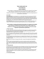
FIG. 4 Locating Hp With Broad Trace
13. Calculation
13.1 Calculation of Data:
13.1.1 Calibration Data:
13.1.1.1 List calibration HP and Iγ in all records.
13.1.1.2 List calibration lambda, obtained as follows, λ in
all records.
(a) Determine and mark the position of maximum IH(HP).
Where the peak is broad determine the position as half the
distance between the points shown in Fig. 4.
(b) Measure the distance from the position of HP to HP/2
(mark on chart paper) and divide by chart speed to obtain λ in
seconds.
13.1.2 Plating Data:
13.1.2.1 List plating HPp and Iγp in all records.
13.1.2.2 List plating lambda obtained, λ p in all records.
13.1.3 Correction of Plating Data:
13.1.3.1 Correct λp to compensate for probe characteristics
as shown.
λ pc 5 λ p 3 ~ 40/λ !
13.1.3.2 Arithmetically average λ pc’s, as shown, for a given
plating solution. See 13.4 to determine the tests required and
which, if any, values of λpc may be eliminated as statistically
being erroneous.
λ¯ Mpc 5
(λ
n
c
(3)
n
I γ pc 5 I γ p 3
I¯ Mγ p 5
pc
100
I γc
(I
n
n
(4)
γ pc
(5)
13.2 Records:
13.2.1 Chart Paper—The following data will be put on the
chart that recorded IH reading for all calibration and plating
tests. Retain charts for twelve months if used for quality
control of low-hydrogen embrittlement plating.
(2)
FIG. 3 Acceptable Range Zones
6
F326 − 96 (2012)
13.4.3.3 If six or more tests have been made in a set,
evaluate in accordance with 13.4.5.
13.4.4 When three or more tests have been made in a set, the
following criterion may be used for discarding an extreme
value:
13.4.4.1 Calculate “R” where
13.2.1.1 Date,
13.2.1.2 Initials of operator,
13.2.1.3 Probe number,
13.2.1.4 Calibration or plating solution identification,
13.2.1.5 Temperature of solution (C),
13.2.1.6 Oven used,
13.2.1.7 Heat peak (written “HP = ____”) and scale factor,
13.2.1.8 Lambda (written “λ = ____ seconds”) and chart
speed where applicable, and
13.2.1.9 Iγ (written “Iγ = ____”).
13.2.2 Logbook—Keep a logbook listing the following for
each run.
13.2.2.1 Run number, consecutive for each test run,
13.2.2.2 Date,
13.2.2.3 Solution identification,
13.2.2.4 Solution temperature,
13.2.2.5 Oven used,
13.2.2.6 λ,
13.2.2.7 HP p,
13.2.2.8 λp,
13.2.2.9 λpc,
13.2.2.10 λ¯ Mpc for set of tests, 3.2.14 and 13.1.3.2. List all
plating run numbers for a set of tests,
13.2.2.11 Iλ pc,
13.2.2.12 Iλ pc, for set of tests, and
13.2.2.13 Operator’s initials.
R5
~ difference between suspect value and next closest value!
~ difference between extreme high and low value!
13.4.4.2 Extreme value may be discarded if “R” exceeds
the value listed in Table 1 for the number of tests in the set
(including the suspect value).
13.4.4.3 If an extreme test value is discarded, reconsider the
reduced set starting at 13.4.2. Initiate additional testing on the
oven from which the test value was discarded.
13.4.5 If, after conducting six tests (seven tests in which one
is discarded), the range is unacceptable and λ¯ Mpc meets
customer criteria, take a new sample of the solution and retest.
Where λ¯ Mpc is greater than customer criteria or retesting still
results in unacceptable range, report data and problem to
customer.
13.4.6 When three or more tests are conducted in a set,
correlate ovens in accordance with 11.7. Where ovens are not
comparable, check oven correlation in a fresh laboratory
plating solution. If agreement is still not obtained, consult the
oven manufacturer.
13.4.7 Where the range is acceptable and, where applicable,
the ovens are comparable, test results are acceptable. Record
λ¯ Mpc in the logbook. This value will be used for plating solution
control.
13.3 Calibration Rules:
13.3.1 Two consecutive calibration λ’s must meet the following criterion before using probe for plating data. The low λ
must be ≥0.778 × high λ or high λ must be ≤1.29 × low λ.
13.3.2 The last calibration will be used to correct the plating
data.
13.3.3 On new probes, each probe must be calibrated two or
more times until the criterion in 13.4.1 is met.
13.3.4 A probe can be used to obtain plating data twice
between calibrations.
13.3.5 After two plating tests, a probe must be recalibrated.
If the recalibration is within the criterion (13.3.1) of the last
calibration, it can be used for two more plating tests. If not, it
must be recalibrated until two consecutive calibrations meet
the criterion.
13.3.6 Probes used for applications other than normal plating tests must be recalibrated before each test.
13.3.7 A probe must be recalibrated if a plating test HP is
greater than 2500.
NOTE 4—It is advisable to conduct a set of at least four tests weekly for
oven correlation.
13.5 Report—Should contain probe number, solution tested,
date, and corrected λpc per 13.1.1.
14. Precision and Bias
14.1 The range expected by competent operators in a
number of laboratories will be within the limits of Fig. 3.
14.2 Bias—This procedure has no bias because the result is
defined only in terms of this test method.
15. Keywords
15.1 cadmium; hydrogen detection instrument; hydrogen
embrittlement
13.4 Determination of Number of Tests Required:
13.4.1 Conduct a set of two tests on the solution sample.
13.4.2 Calculate λ¯ Mpc and range of the set (13.1.3.2).
13.4.3 Consult Fig. 3 to see if λ¯ Mpc is acceptable for “N ”
tests.
13.4.3.1 If acceptable, discontinue testing and evaluate. In
accordance with the procuring agencies criteria.
13.4.3.2 If unacceptable, conduct another test on the solution sample and reconsider the set starting with 13.4.2.
TABLE 1 Evaluation Table for Invalid Test Criterion
7
Number of Tests
in Set
R
3
4
5
6
7
0.941
0.765
0.642
0.560
0.507
F326 − 96 (2012)
ASTM International takes no position respecting the validity of any patent rights asserted in connection with any item mentioned
in this standard. Users of this standard are expressly advised that determination of the validity of any such patent rights, and the risk
of infringement of such rights, are entirely their own responsibility.
This standard is subject to revision at any time by the responsible technical committee and must be reviewed every five years and
if not revised, either reapproved or withdrawn. Your comments are invited either for revision of this standard or for additional standards
and should be addressed to ASTM International Headquarters. Your comments will receive careful consideration at a meeting of the
responsible technical committee, which you may attend. If you feel that your comments have not received a fair hearing you should
make your views known to the ASTM Committee on Standards, at the address shown below.
This standard is copyrighted by ASTM International, 100 Barr Harbor Drive, PO Box C700, West Conshohocken, PA 19428-2959,
United States. Individual reprints (single or multiple copies) of this standard may be obtained by contacting ASTM at the above
address or at 610-832-9585 (phone), 610-832-9555 (fax), or (e-mail); or through the ASTM website
(www.astm.org). Permission rights to photocopy the standard may also be secured from the Copyright Clearance Center, 222
Rosewood Drive, Danvers, MA 01923, Tel: (978) 646-2600; />
8