Astm f 615m 95 (2013)
Bạn đang xem bản rút gọn của tài liệu. Xem và tải ngay bản đầy đủ của tài liệu tại đây (119.35 KB, 5 trang )
Designation: F615M − 95 (Reapproved 2013)
Standard Practice for
Determining Safe Current Pulse-Operating Regions for
Metallization on Semiconductor Components (Metric)1
This standard is issued under the fixed designation F615M; the number immediately following the designation indicates the year of
original adoption or, in the case of revision, the year of last revision. A number in parentheses indicates the year of last reapproval. A
superscript epsilon (´) indicates an editorial change since the last revision or reapproval.
3.2 The d-c resistance of each specimen is measured.
1. Scope
1.1 This practice covers procedures for determining operating regions that are safe from metallization burnout induced by
current pulses of less than 1-s duration.
3.3 Each specimen is subjected to stress from rectangular
current pulses varying in amplitude and duration according to
a predetermined schedule of pulse width and amplitudes.
NOTE 1—In this practice, “metallization” refers to metallic layers on
semiconductor components such as interconnect patterns on integrated
circuits. The principles of the practice may, however, be extended to
nearly any current-carrying path. The term “burnout” refers to either
fusing or vaporization.
3.4 A second d-c resistance measurement is made on each
specimen after each pulse, and it is characterized as having
failed or survived.
3.5 The number, x, of specimens surviving and the total
number, n, of specimens tested at each pulse width and
amplitude are analyzed statistically to determine the burnout
level at each test pulse width for the desired burnout survival
probability and confidence level.
1.2 This practice is based on the application of unipolar
rectangular current test pulses. An extrapolation technique is
specified for mapping safe operating regions in the pulseamplitude versus pulse-duration plane. A procedure is provided
in Appendix X2 to relate safe operating regions established
from rectangular pulse data to safe operating regions for
arbitrary pulse shapes.
3.6 A point corresponding to the burnout level (at the
desired probability and confidence level) is plotted for each of
the test pulse duration values in the pulse-amplitude, pulseduration plane. Based on these points, an extrapolation technique is used to plot the boundary of the safe operating region.
1.3 This practice is not intended to apply to metallization
damage mechanisms other than fusing or vaporization induced
by current pulses and, in particular, is not intended to apply to
long-term mechanisms, such as metal migration.
3.7 The following items are not specified by the practice and
are subject to agreement by the parties to the test:
3.7.1 The procedure by which the specimens are to be
selected.
3.7.2 Test patterns that will be representative of adjacent
metallization on a die or wafer (5.3).
3.7.3 The schedule of pulse amplitudes and durations to be
applied to the test samples (9.8).
3.7.4 The level of probability and confidence to be used in
calculations to establish the boundary of the safe operating
region (10.1).
3.7.5 The amount of change of resistance that will define the
criterion for failure.
3.7.6 The statistical model to be used to determine the
burnout probability at a desired stress level.
3.7.7 The form and content of the report.
1.4 This practice is not intended to determine the nature of
any defect causing failure.
1.5 This standard does not purport to address all of the
safety concerns, if any, associated with its use. It is the
responsibility of the user of this standard to establish appropriate safety and health practices and determine the applicability of regulatory limitations prior to use.
2. Terminology
2.1 Definitions of Terms Specific to This Standard:
2.1.1 failure—a change in the measured resistance of
610 % ∆R/R or as agreed upon by the parties to the test.
3. Summary of Practice
3.1 Specimens are selected from the population being evaluated.
4. Significance and Use
4.1 Solid-state electronic devices subjected to stresses from
excessive current pulses sometimes fail because a portion of
the metallization fuses or vaporizes (suffers burnout). Burnout
susceptibility can vary significantly from component to component on a given wafer, regardless of design. This practice
1
This practice is under the jurisdiction of ASTM Committee F01 on Electronics
and is the direct responsibility of Subcommittee F01.11 on Nuclear and Space
Radiation Effects.
Current edition approved May 1, 2013. Published May 2013. Originally
approved in 1995. Last previous edition approved in 2008 as F615M-95(2008).
DOI: 10.1520/F0615M-95R13.
Copyright © ASTM International, 100 Barr Harbor Drive, PO Box C700, West Conshohocken, PA 19428-2959. United States
1
F615M − 95 (2013)
6.1.1 Risetime and falltime less than 10 % of the pulsewidth
(full width at half maximum amplitude (FWHM)),
6.1.2 Impedance high enough with respect to the specimen
metallization so that the pulse amplitude remains constant to
within 65 % between the end of the rise and beginning of the
fall,
6.1.3 Jitter in the pulse amplitude and width less than6 5 %,
6.1.4 Current amplitude and pulsewidth capability to provide pulses as agreed upon by the parties to the test, and
6.1.5 Single-pulse capability.
provides a procedure for establishing the limits of pulse current
overstress within which the metallization of a given device
should survive.
4.2 This practice can be used as a destructive test in a
lot-sampling program to determine the boundaries of the safe
operating region having desired survival probabilities and
statistical confidence levels when appropriate sample quantities
and statistical analyses are used.
NOTE 2—The practice may be extended to infer the survivability of
untested metallization adjacent to the specimen metallization on a
semiconductor die or wafer if care is taken that appropriate similarities
exist in the design and fabrication variables.
NOTE 6—Refer to Appendix X2 for information relating a rectangular
pulse to an arbitrary pulse structure.
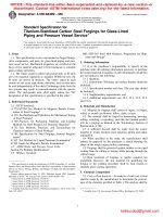
6.2 Pulse-Monitoring Equipment , as follows:
6.2.1 Voltage-Monitoring Kelvin Probe , for use in the
circuit of Fig. 1, with risetime less than or equal to 5 % of the
pulsewidth of the shortest pulse to be applied, and shunt
capacitance sufficiently low so that the pulse shape is not
distorted more than specified in 6.1:
6.2.2 Voltage-Monitoring Resistor (R, Fig. 1), with sufficiently low inductance, resistance, and shunt capacitance so
that the generated pulse is not distorted more than specified in
6.1 and the value of the resistance is known within 61 %.
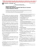
6.2.3 Current Probe, for use in the circuit of Fig. 2, with
risetime less than or equal to 5 % of the pulsewidth of the
shortest pulse to be applied, with an ampere-second product
sufficient to ensure nonsaturation for the amplitudes and
durations of the pulses to be used and accurate within 65 %.
5. Interferences
5.1 The level at which failure of metallization subjected to
pulsed-current overstress occurs may be dependent on the
temperature experienced by the semiconductor device. If
significant differences in ambient temperature or heat sinking,
or both, exist between one test situation and another, the results
may not be representative.
NOTE 3—See Appendix X1 for a discussion of factors related to
metallization heat sinking.
5.2 If probes are used to contact the metallization specimen,
suitable precautions must be taken or the results may be
misleading. The probes must not be allowed to come into
contact with the area of metallization being characterized.
5.2.1 The use of Kelvin probe connections to make the
resistance measurements is usually required to prevent contact
resistance (at the current injection point) from interfering with
the measurement.
5.2.2 Probe contacts with excessive contact resistance may
cause damage at the point of contact. Such damage can
interfere with the measurement.
6.3 Pulse-Recording Equipment, transient digitizer, oscilloscope with camera, storage oscilloscope, or other pulse recording means having a risetime less than 5 % of the width of the
shortest test pulse used and capable of recording individual test
pulses.
6.4 Test Fixture, providing means for the current pulse to be
transmitted through the metallization specimen as well as
through an equivalent resistance (see 9.5) without distortion of
the pulse shape beyond that specified in 6.1. The test fixture
must also provide a means for connecting the metallization
specimen to the resistance-measuring equipment (see 6.5). The
test fixture will contact the specimen through either standard
component package leads or wafer probes. More than one test
fixture may be used.
5.3 If the test is used to infer the survivability of metallization on a wafer or die, the results could be misleading unless
such factors as the following are identical: (1) metallization
design geometry, (2) oxide step geometry, and (3) orientation
of the metallization paths and oxide steps to the metallization
source during deposition.
NOTE 4—The design and fabrication factors listed in 5.3 have been
shown to be important for systems of aluminum metallization deposited
on SiO2/Si substrates. They are given as examples and are not intended to
be all inclusive or necessarily to apply to all metallization systems to
which this practice may be applied.
NOTE 5—Variations in oxide step geometry must be expected (see
X1.4.2).
6.5 Resistance-Measuring Equipment—A curve tracer,
ohmmeter, or other means to be used for evaluating the d-c
resistance and continuity of the current path on the specimen.
The current through the specimen during this measurement
should be minimized (less than 10 % of the d-c current rating
of the specimen).
5.4 A step-stress pulsing schedule is not recommended. If
such a schedule is used so that each specimen is subjected to
successive pulses of increasing amplitude until failure occurs,
the results could be misleading. It is possible that a pulse of the
proper level can cause melting at a defect site without causing
an open circuit; the molten metal may become redistributed so
that the defect appears cured and will lead to failure on
successive pulses.
6. Apparatus
6.1 Current-Pulse Generator—A source of rectangular current pulses capable of meeting the following requirements:
FIG. 1 Pulsing Circuit Using Resistor Voltage Drop to Monitor
Current Through Specimen
2
F615M − 95 (2013)
9.9 Measure and record the specimen resistance (see 9.3 and
9.4).
9.10 Compare the value recorded in 9.9 with that recorded
in 9.4. Characterize the specimen as failed if the resistance of
the specimen has increased by the amount agreed upon by the
parties to the test. Otherwise, characterize the specimen as
survived. Record the characterization.
FIG. 2 Pulsing Circuit Using Current Probe to Monitor Current
Through Specimen
9.11 Repeat 9.3 through 9.10 for each specimen in the
sample at each of the scheduled pulse amplitudes and
durations, and record the number failing, xτI, and the number
tested, nτI, at each pulse amplitude and duration.
6.6 Miscellaneous Circuit Components, to be used as required in each of the test circuits (see Fig. 1 or Fig. 2). The
switches, leads, and connections shall be of a quality used
customarily in electronic circuit testing.
10. Calculation and Interpretation of Results
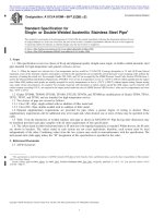
10.1 Determine the safe operating region for general pulse
duration, t, as indicated by Fig. 3. For each data point (τ, I), a
safe operating region includes all points falling below the curve
Is (t) as follows:
6.7 Resistors, as required, to match the d-c resistance of the
unstressed specimen to within 65 %.
7. Sampling
7.1 The procedure by which the sample is to be taken and
the number of specimens for each test condition are not
specified by this practice and are to be agreed upon by the
parties to the test.
I s~ t ! 5 I τ
Œ
τ
,t$τ
t
where:
τ = test pulse width.
8. Test Specimen
10.2 If more than one data point (τ, Iτ) has been established,
the upper bound of the safe operating region is defined by the
smallest value of Is(t) at any t as defined by all data points.
8.1 The specimen may be an integrated circuit or a special
test structure for the evaluation of a design or process,
depending on the purpose for which the measurements are to
be used.
NOTE 8—See Appendix X2 for a method of extending these results to
arbitrary pulse shape.
9. Procedure
11. Report
9.1 Assemble the pulsing circuit shown in either Fig. 1 or
Fig. 2, so that a specimen can be connected via a suitable test
fixture into the test circuit.
11.1 The contents of the test report will vary depending on
the purpose of the test. The specific format and content for the
report (including the specific format in which the safeoperating area data is presented) are to be agreed upon by the
parties to the test prior to the start of the test program.
9.2 Turn on all equipment, and allow the apparatus to warm
up in accordance with the manufacturer’s instructions.
9.3 Connect the specimen to a suitable test fixture to
measure the resistance of the specimen. If probes are used to
contact the specimen, see 5.2 for precautions.
12. Keywords
12.1 current pulse; current pulse burnout; metallization
burnout; safe current pulse; semiconductor burnout
NOTE 7—Appropriate handling precautions must be taken to prevent
electrostatic damage.
9.4 Measure and record the specimen resistance, in ohms or
continuity, as required.
9.5 Connect an equivalent resistance into the pulse testing
circuit and, by applying pulses through this resistor, establish
and record the pulser settings required to generate the pulse
amplitudes to be applied to the specimen and the appropriate
settings for the pulse-monitoring equipment.
9.6 Connect the specimen into the pulsing circuit.
9.7 Set the current pulse generator and pulse monitoring
equipment for a pulse of the designated amplitude and duration
in accordance with the information recorded in 9.5.
NOTE 1—The safe operating region is that region of the l, t plane below
the solid boundary line.
9.8 Apply a single pulse of the scheduled amplitude and
duration to the specimen.
FIG. 3 Example of a Safe Operating Region
3
F615M − 95 (2013)
APPENDIXES
(Nonmandatory Information)
X1. METALLIZATION BURNOUT MECHANISMS
X1.3 Calculation of Adiabatic Time Dependence for
Melting in Aluminum
X1.1 Scope
X1.1.1 This appendix describes the mechanisms involved in
metallization burnout, as addressed in the practice. This practice deals with burnout failures that occur as the result of
current pulses of less than 1-s duration.
X1.3.1 For aluminum metallization, the functions c(T) and
ρ( T) are approximately linear and of the form y = mx + b,
where the parameters m and b can be determined from data
such as those given in the Handbook of Chemistry and
Physics. 2
X1.3.1.1 Thus, for aluminum heated from room temperature
(;22°C) to the melting temperature during the interval t1 to t2,
(Eq X1.2) becomes as follows:
X1.1.2 When metal interconnections on semiconductor
components (semiconductor metallization) are damaged by
current pulses of such duration, the damage is generally a result
of resistive heating in the metallization (often at defect sites),
which causes the metallization to melt, vaporize, or both.
Semiconductor metallization can also burn out as a secondary
result of heating in the underlying semiconductor material.
This practice and the following discussion are aimed at
mechanisms associated with resistive heating in the metallization. The practice is intended to define safe operating regions in
which such failures will not occur and is not intended to
determine the nature of any defect causing failure.
t2
* J ~ x, t ! dt 5 2.3 3 10
2
8
A 2 ·s/cm4
(X1.3)
t1
X1.3.1.2 To melt the aluminum, the heat of fusion must be
added during a time interval t2 to t3. Using the heat of fusion
from the Handbook of Chemistry and Physics, 2 we can write
as follows:
t3
X1.2 Equations of Resistive Heating
* J ~ x, t ! dt 5 0.92 3 10
X1.2.1 When an electrically resistive material is subjected
to an electrical current, the differential equation for temperature rise at any point x is as follows:
* J ~ x, t ! dt 5 3.2 3 10
]H
dT
Dc~ T !
5 J 2 ~ x, t ! p ~ T ! 2
~ x, t !
dt
]t
2
2
(X1.1)
2
(X1.5)
(X1.6)
X1.4 Discussion of General Time Dependence
X1.4.1 From the results of the preceding calculations, we
see that the failure current has a τ − ⁄ dependence in the
adiabatic case. For a metallization strip of uniform cross
section deposited on a planar substrate such as the common
SiO2/Si semiconductor construction, the adiabatic condition is
applicable for pulse durations much less than the characteristic
thermal relaxation time τc, which is given as follows:
12
τc 5
cmx
K
(X1.7)
where:
c = specific heat of the metallization,
m = mass per unit area of the metallization,
x = thickness of the layer between the metallization and its
heat sink, and
K = thermal conductivity of the layer between the metallization and its heat sink.
t2
* J ~ x, t ! dt
A 2 ·s/cm4
I/A 5 1.8 3 104 τ p 21/2 A/cm2
X1.2.2 The term ∂H/∂t is dependent on the particular
geometry, material, and ambient conditions. For general
considerations, it is of interest to analyze the adiabatic case. In
that case, ∂H/∂t is negligible and (Eq X1.1) can be rearranged
and integrated directly as follows:
T1
8
X1.3.2 For a square pulse of current I and duration τρ
through a metallization strip of cross-sectional area A, the
current density required to cause complete melting in the
adiabatic case is then as follows:
Any self-consistent set of units may be used.
*
(X1.4)
t1
= temperature,
= density of the material,
= temperature-dependent specific heat of the
material,
ρ(T)
= temperature-dependent resistivity of the
material,
J(x, t)
= time-dependent current density at position x,
and
∂H⁄∂t (x, t)
= rate of thermal energy loss per unit mass from
an increment of material at position x.
c~T!
dT 5
ρ~T!
A 2 ·s/cm4
t3
where:
T
D
c(T)
T2
8
t2
(X1.2)
t1
where:
T2 − T1 = temperature rise at x caused by current flow in the
time period t1 to t2.
2
The 42nd edition is available from the Chemical Rubber Publishing Co.,
Cleveland, OH, 1960.
4
F615M − 95 (2013)
which typically occurs in semiconductor components, is thin
metal over an oxide step outlining a junction diffusion. Such
defects are generally so narrow that ∂H/∂t is controlled by heat
flow from the site to the surrounding metallization.
Typical values of τc for such a system are of the order of 1
µs.
X1.4.2 For a metallization strip containing points of reduced cross section, melting occurs first at the smallest
cross-section site having τc ≥ τp. An example of such a defect,
X2. EXTENSION OF RECTANGULAR CURRENT PULSE DATA TO THE ANALYSIS OF
ARBITRARY CURRENT PULSE DATA FOR CAUSING METALLIZATION BURNOUT
approximately applicable with current substituted for power.
The desired safe pulse amplitude for any pulse waveform IA (τ)
is then defined as follows:
X2.1 A useful method for relating rectangular pulse burnout
data to arbitrary pulse shapes has been developed by Tasca, et
al. 3 In that method, a convolution integral is formed involving
arbitrary pulse power waveforms and the dependence of square
pulse power on pulse duration. For metallization burnout,
where purely resistive heating is involved, the method is
τA
1.
*I
O
2
A
H
d
F
1
~λ! d~τ 2 λ! I 2 ~τ 2 λ!
s
GJ
dλ
(X2.1)
where:
Is(t) = rectangular pulse current required to cause burnout,
τA
= time to failure from a pulse of arbitrary form IA(t) ,
and
λ
= a dummy variable for integration purposes.
3
Tasca, D. M., Peden, J. C., and Andrews, J. L., “Theoretical and Experimental
Studies of Semiconductor Device Degradation Due to High Power Electrical
Transients,” General Electric Document No. 735D4289, December 1972, as
Acquisition No. 20212 from FCDNA, Attn: DASIAC, 1680 Texas St., SE, Kirtland
AFB, NM 87117.
ASTM International takes no position respecting the validity of any patent rights asserted in connection with any item mentioned
in this standard. Users of this standard are expressly advised that determination of the validity of any such patent rights, and the risk
of infringement of such rights, are entirely their own responsibility.
This standard is subject to revision at any time by the responsible technical committee and must be reviewed every five years and
if not revised, either reapproved or withdrawn. Your comments are invited either for revision of this standard or for additional standards
and should be addressed to ASTM International Headquarters. Your comments will receive careful consideration at a meeting of the
responsible technical committee, which you may attend. If you feel that your comments have not received a fair hearing you should
make your views known to the ASTM Committee on Standards, at the address shown below.
This standard is copyrighted by ASTM International, 100 Barr Harbor Drive, PO Box C700, West Conshohocken, PA 19428-2959,
United States. Individual reprints (single or multiple copies) of this standard may be obtained by contacting ASTM at the above
address or at 610-832-9585 (phone), 610-832-9555 (fax), or (e-mail); or through the ASTM website
(www.astm.org). Permission rights to photocopy the standard may also be secured from the Copyright Clearance Center, 222
Rosewood Drive, Danvers, MA 01923, Tel: (978) 646-2600; />
5