Astm astm f 1063 09 (2014)
Bạn đang xem bản rút gọn của tài liệu. Xem và tải ngay bản đầy đủ của tài liệu tại đây (197.06 KB, 9 trang )
Designation: F1063 − 09 (Reapproved 2014)
Standard Practice for
Functional Inspections and Adjustments of Alpine Ski/
Binding/Boot Systems1
This standard is issued under the fixed designation F1063; the number immediately following the designation indicates the year of
original adoption or, in the case of revision, the year of last revision. A number in parentheses indicates the year of last reapproval. A
superscript epsilon (´) indicates an editorial change since the last revision or reapproval.
INTRODUCTION
Adhering to these guidelines may help reduce the risk of injuries resulting from improper
mechanical functioning of releasable alpine binding systems. Skiing involves inherent risks and injury
can result from simply falling down, impact with an object, or from many other actions. Many injuries
are unrelated to system function and a properly functioning system cannot protect the skier in all
situations. Compliance with these guidelines in no way guarantees that injury will be prevented.
1. Scope
and Incomplete Alpine Ski/Binding/Boot Systems in
Rental Applications
1.1 This practice provides procedures for inspection and
adjustment of alpine ski/binding/boot systems.
3. Terminology
1.2 This practice should be followed for systems, whether
newly mounted or previously mounted, when work is performed on the system that may affect its release function,
unless otherwise specified by the binding manufacturer in
non-rental applications.
3.1 Definitions:
3.1.1 clean versus lubricated tolerance—accepted difference between clean and lubricated test results, defined as not
more than 20 % of the clean test, used whenever a functional
test for binding-boot compatibility is required (see 6.3).
3.1.2 clockwise versus counterclockwise tolerance—
accepted difference between test results about an axis perpendicular to the plane of the ski, usually from the toe piece
component, and defined as within the inspection tolerance.
3.1.3 corrective action—procedures other than readjustment
of the visual indicator setting (see 3.1.18) to include repair or
replacement of system components.
3.1.4 deviation—difference between the test result (see
3.1.16) and the selected reference torque value (see 3.1.12),
usually expressed as a percentage of the selected reference
torque value.
3.1.5 in use tolerance—accepted difference between the
reference torque value and the test result(s), defined as 630 %
of the reference torque value, or 65 Nm for twist and 20 Nm
for forward lean, whichever is greater, or two horizontal rows
up or down from the selected reference torque value determined on the binding manufacturer’s adjustment chart. In the
absence of an applicable manufacturer’s chart, use Annex A2.
For non-rental applications, this tolerance is used as the upper
and lower limit for determining if system release values are
acceptable for in-use or in-service purposes, after said system
has been released to the customer. This limit is derived from
Practice F1064, 3.1.1 Class 1 deviation. This deviation (616 to
30 %, or two horizontal rows up or down from the selected
reference torque value) is defined as a minor deviation that
1.3 Nonapplicability of this function and release inspection
practice to rental shop operations is based upon the existence of
applicable ASTM practices.
NOTE 1—Refer to Practice F1064 for equivalent procedures and
tolerances for complete and incomplete rental systems.
1.4 The values stated in SI units are to be regarded as
standard. No other units of measurement are included in this
standard.
2. Referenced Documents
2.1 ASTM Standards:2
F939 Practice for Selection of Release Torque Values for
Alpine Ski Bindings
F1061 Specification for Ski Binding Test Devices
F1064 Practice for Sampling and Inspection of Complete
1
This practice is under the jurisdiction of ASTM Committee F27 on Snow
Skiing and is the direct responsibility of Subcommittee F27.50 on Shop Procedures
(Retail and Rental).
Current edition approved July 1, 2014. Published July 2014. Originally approved
in 1989. Last previous edition approved in 2009 as F1063 – 09. DOI: 10.1520/
F1063-09R14.
2
For referenced ASTM standards, visit the ASTM website, www.astm.org, or
contact ASTM Customer Service at For Annual Book of ASTM
Standards volume information, refer to the standard’s Document Summary page on
the ASTM website.
Copyright © ASTM International, 100 Barr Harbor Drive, PO Box C700, West Conshohocken, PA 19428-2959. United States
1
F1063 − 09 (2014)
3.1.14 skier type—classification, selected by the skier, for
the type of skiing to be undertaken.
3.1.14.1 Type I—designation that provides lower than average release/retention values; corresponds to an increased risk
of inadvertent binding release in order to gain releasability in
a fall; also applies to entry level skiers uncertain of their
classification.
3.1.14.2 Type II—designation that provides average release/
retention values appropriate for most recreational skiing;
applies to skiers not classified as in Type I or Type III.
3.1.14.3 Type III—designation that provides higher than
average release/retention values; corresponds to decreased
releasability in a fall in order to gain a decreased risk of
inadvertent binding release.
3.1.14.4 (/)—a symbol that separates skier type
designations, used when, as a result of troubleshooting, different skier types have been selected for determining twist (Mx),
and forward lean (Mz) release/retention values; shown in the
order (twist/forward lean) or (T/H) to denote toe piece (T) and
heel piece (H) of this ski binding. Other conventions may be
used to record different skier types for twist and forward lean
when required by the documentation
3.1.15 system—group of interacting components, usually
comprised of a ski, binding, and boot.
3.1.16 test result—middle quantitative value of three repetitions of the same test.
3.1.17 troubleshooting—binding manufacturer’s recommendations or procedures of analyzing system failure.
3.1.18 visual indicator setting—setting displayed on the
binding’s release/retention adjustment scale.
does not require corrective action for equipment that is
in-service, in rental applications. It is used as the upper and
lower limit for readjustment of the binding.
3.1.6 initial visual indicator setting—visual indicator setting
derived from the binding manufacturer’s adjustment chart.
3.1.7 inspection tolerance—accepted difference between the
reference torque value and the test result. Defined as 615 % of
the reference torque value, or 63 Nm for twist and 610 Nm
for forward lean, whichever is greater, or one horizontal row up
or down from the selected reference torque value determined
on the binding manufacturer’s adjustment chart, (see Annex
A2). It is used as the criteria for prompting consultation of the
binding manufacturer’s troubleshooting procedures or readjustment of the binding, or a combination of both.
3.1.7.1 Discussion—When an algorithm or table is used to
provide a value, either may be used (differences may be
insignificant).
3.1.8 limit for readjustment—accepted difference between
the reference torque value (see 3.1.12) and test result(s) (see
3.1.16), defined as 630 % of the reference torque value, or 65
Nm for twist and 20 Nm for forward lean, whichever is greater,
or two horizontal rows up or down from the selected reference
torque value determined on the binding manufacturer’s adjustment chart (see Annex A2). For a reference torque value of 8
Nm in twist and 29 Nm in forward lean (Skier Code A in
Annex A2), the limit for readjustment is one row up or two
rows down on the adjustment chart. The limit for readjustment
is used as the upper and lower limit for readjustment of the
binding.
3.1.9 measured release value—release torque value determined by the use of a testing device of the type defined in
Annex A1.
4. Significance and Use
3.1.10 readjustment value—value that shall be added or
subtracted from the initial visual indicator setting to bring the
test result within the inspection tolerance.
4.1 The purpose of this practice is to aid in providing the
end user with an appropriately functioning system with appropriate release torque setting(s).
3.1.11 release/retention value—release torque of the ski/
binding/boot system.
4.2 The definitions and tolerances defined in this practice do
not necessarily apply to procedures incorporating an inspection
interval or schedule, in which such procedures are specified by
the binding manufacturer. This practice is not intended to be a
method for evaluating equipment design.
3.1.11.1 discretionary settings—visual indicator settings
higher or lower than the normal setting range
(1) (–)—a symbol, that when placed to the left of Type 1
(see 3.1.14.1), provides release/retention values lower than
Type I, corresponds to a further increase in the risk of
inadvertent binding release in order to gain increased releasability in a fall.
(2) (+)—a symbol, that when placed to the right of Type III
(see 3.1.14.3), provides release/retention values higher than
Type III, corresponds to a further decrease in releasability in a
fall in order to gain a decreased risk of inadvertent binding
release.
NOTE 2—Refer to Practice F1064 for definitions and tolerances pertaining to the evaluation of equipment once in use.
5. Procedure
5.1 Inspections— Two types of inspection procedures are
described in this practice: (1) procedures to check the system
for appropriate function, and (2) procedures to check the
system for appropriate release torque calibration (see Appendix
X4). In all procedures requiring a measured release value, the
system testing device should meet Specification F1061 and be
checked by the method described in Annex A1.
5.1.1 Functional Inspections—These inspections shall include inspection of all boot-to-binding adjustments and
clearances, appropriate elastic travel (see 6.1), symmetry of
torsional release, boot-binding compatibility (see 6.3), and
3.1.12 reference torque value—nominal release torque value
derived from a document compatible with Practice F939, such
as Annex A2, or information supplied by the binding or test
device manufacturer.
3.1.13 skier code—letter code derived from the binding
manufacturer’s adjustment chart, based on a skier’s parameters
(height, weight, age, and skier type).
2
F1063 − 09 (2014)
detergent solution may be used to help clean the system,
provided all surfaces are flushed with clean water afterwards.
other inspections recommended by the equipment manufacturers (see Appendix X4).
5.1.2 Release Torque Value Inspections—The release torque
value of the system, as assembled for use, shall be inspected
with the use of a system testing device (see Annex A1). A
description of release torque value inspections and tolerances is
included in this practice (see Section 7 and Appendix X4).
7. Release Torque Inspections
7.1 Tests for Twist Release—A test should be performed to
determine the torque required to release the binding in twist
(Mz) about an axis perpendicular to the plane of the boot sole.
This test should be performed using a device of the type
described in Annex A1 and should be performed in both
clockwise and counterclockwise directions of release. Test
results should be within the appropriate inspection tolerance.
Units that exceed the inspection tolerance should be readjusted
to test within the inspection tolerance. When an initial visual
indicator setting is used (see Appendix X4), readjustment
should not be attempted if test result(s) exceed the limit for
readjustment without first taking corrective action as specified
by the binding manufacturer.
5.2 Reference Torque Value Selection—Reference torque
values for release torque may be selected using Annex A2 or
tables supplied by the binding manufacturer or system testing
device manufacturer, which are in accordance with Practice
F939. Reference torque values above the upper limit specified
by Practice F939 or above the binding manufacturer’s recommendations should not be used. Values below the lower limit or
below the binding manufacturer’s recommendations may be
used unless the binding manufacturer recommends against
such procedures.
7.2 Tests of Forward Lean Release—A test should be made
to determine the torque required to release the binding in
forward lean. This test should be made using a device of the
type described in Annex A1. Test result(s) should be within the
inspection tolerance. Units that exceed the inspection tolerance
should be readjusted to within the inspection tolerance. When
an initial indicator setting is used (see 3.1.6 and Appendix X4),
readjustment should not be attempted if test result(s) exceed
the limit for readjustment without first taking corrective action
as specified by the binding manufacturer (see 3.1.1 and 3.1.7).
7.2.1 If no independent means are provided to adjust the
forward lean release, this test should be used to ensure the ratio
of forward lean to twist release is as specified by the manufacturer.
6. Functional Inspections
6.1 Test for Elastic Travel and Recentering—The system
should be exercised to ensure the boot or plate can travel a
distance specified by the manufacturer and return freely to
within 2 mm of the original position. This test should be made
in all directions of release and in a manner specified by the
binding manufacturer. If no displacement is specified, then
displacement of 5 mm measured at the toe or heel (as
appropriate) should be used and the test should be performed
by any device or method capable of displacing the boot or plate
the necessary distance.
6.2 Test for Symmetrical Release—The system should be
tested for twist release in both the clockwise and counterclockwise directions with a device of the type specified in Annex
A1.
7.3 Other Release Tests—Tests of the type in 7.1 and 7.2
should be made in any other direction specified by the binding
manufacturer.
6.3 Test of Boot/Binding Compatibility—Used as a diagnostic inspection for determining the compatibility of a boot and
binding used in a system. The boot should be of a shape,
composition, construction, and condition acceptable to the
binding manufacturer. Functional inspections specified by the
binding manufacturer to determine the compatibility of the
boot and binding should be performed. If no functional
inspection procedures are specified by the binding
manufacturer, a functional inspection should be performed to
determine the difference in test results between a clean, dry
boot/binding system and the same system after lubrication of
all boot/binding interfaces. This functional inspection should
be made in all directions of release specified by the binding
manufacturer, using a device of the type specified in Annex A1
(see 5.1).
6.3.1 The lubricant used for this test should be applied in a
thin film and may be of any type specified by the boot or
binding manufacturer. If unspecified, a liquid detergent or soap
or a lubricant of a type normally accepted in the maintenance
of the binding, such as a grease or silicone spray lubricant, may
be used. If a spray lubricant is used, ensure that overspray does
not contaminate other systems.
6.3.2 If there is reason to believe a boot/binding interface or
system has been contaminated, a common dishwashing soap or
8. Test Conditions
8.1 Visual Indicator Setting for Functional Inspections—All
functional inspections should be performed at a setting provided by the binding manufacturer. If no manufacturer recommendations are provided, all functional inspections should be
performed at the setting selected for the skier.
8.2 Release Adjustment for Validating Visual Indicator
Setting—Tests to validate the visual indicator setting should be
made in accordance with the procedures specified by the
binding manufacturer.
8.3 Binding Preconditioning—The binding should be cycled
at least once in all directions prior to calibration of the
release/retention value or validation of the visual indicator
setting. Once all functional inspections have been completed
on the system, a lubricant may be used on the boot-binding
interfaces, unless otherwise specified by the binding manufacturer.
NOTE 3—The use of a lubricant is not intended to improve the
performance of the system in use but to reduce the boot-binding friction.
8.4 Temperature—Tests should be performed at temperatures between 10 and 25°C.
3
F1063 − 09 (2014)
8.5 Load Rate—Tests should be performed at a load rate
specified by the manufacturer of the testing device or in
accordance with the binding manufacturer’s recommendations.
If no recommendations are provided, the load required to
release the boot or plate from the binding should be applied
smoothly in such a way that the time to achieve release is
between 1 and 5 s.
9.1.1 Skier parameters,
9.1.2 Visual indicator settings, and
9.1.3 Pass/fail result of the system inspection.
10. Miscellaneous
10.1 Some other functional inspections that may be considered in diagnostic procedures are described in Appendix X1
and Appendix X2.
9. Report/Workshop Ticket
9.1 In principal, a report/workshop ticket is generated by the
ski shop and delivered to the user. It shall contain at least the
following information:
11. Keywords
11.1 retail standard; ski, binding, boot system testing
ANNEXES
(Mandatory Information)
A1. TESTING DEVICE INSPECTION REQUIREMENTS
A1.1 Definition
A1.3.2 The calibration of the test device is checked by a
procedure recommended by either the test device manufacturer
or system manufacturer.
A1.1.1 For the purposes of this practice, a testing device is
defined as any piece of equipment capable of indicating the
torque or force required to release the boot or plate.
A1.3.3 The calibration is checked at three points over the
range in which the test device is intended to be used or as
specified by the test device manufacturer.
A1.1.2 Testing equipment should be of a type that conforms
to Specification F1061.
A1.3.4 The test device is corrected by means of an adjustment to the indicator, if necessary, to read within 65 % or
62.5 Nm, whichever is greater, of the desired value.
A1.2 Inspection Schedule
A1.2.1 The test device is inspected prior to preseason
testing and at least once during the skiing season or whenever
it is apparent that the device is not performing as intended, or
both.
A1.3.5 If a dead weight is used, its weight should be known
to be accurate within 62 %.
A1.3 Inspection
A1.3.6 Calibration of the testing device may also be made
with respect to a reference binding if recommended by the
manufacturer.
A1.3.1 The test device is inspected in accordance with all
procedures recommended by the manufacturer of the test
device or by the manufacturer of the system to be tested (if
appropriate).
A1.3.7 A reference boot or binding, if used, is as recommended by the manufacturer for that purpose and tested with
all surfaces lubricated, unless otherwise specified in the manufacturer’s procedures.
A2. RELEASE TORQUE SELECTION PROCEDURES
A2.1 See Appendix X1 through X3 in Practice F939.
4
F1063 − 09 (2014)
APPENDIXES
(Nonmandatory Information)
X1. EXAMPLE OF TEST METHOD FOR REPRODUCIBILITY AMONG OPERATORS
X1.1 Scope
X1.1.1 This test method covers procedures that may be
supplied by the test device manufacturer to the user for the
purpose of evaluating reproducibility among operators.
X1.2 Procedure
X1.2.1 Select a ski/binding/boot system typical of equipment in use and adjust the visual indicator setting until the
measured release value falls within the approximate middle of
the range of release for the test device.
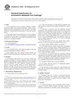
X1.2.2 Randomly order a series of tests in which each
operator performs five repetitions of the test (see example, Fig.
X1.1).
X1.2.3 Designate one person to make all observations. The
observer should not perform any tests.
X1.2.4 Conduct all training recommended by the test device
manufacturer.
NOTE 1—(B) denotes test sequence.
X1.2.5 Conduct all tests in the order determined in X1.2.2.
FIG. X1.1 Data and Calculation Sheet for Multiple-Operator Reproducibility Test
X1.2.6 Do not allow the operators to observe each other or
the results of any tests.
X1.4 Evaluation
X1.4.1 Variability among operators of more than 15 %
should prompt continued training and retesting.
X1.2.7 Observe and record the test results to the resolutions
specified by the test device manufacturer.
X1.2.8 Perform tests in only one direction of release. Repeat
the entire procedure for other directions as appropriate.
X1.5 Other Uses for This Test Method
X1.5.1 This test method may be used to evaluate multiple
observers of the test device scale using a single operator.
X1.5.2 This test method also may be modified to evaluate
multiple observers of other scales such as the visual indicator
setting scale of the binding. These other test methods may
require criteria for evaluation different from X1.4.1.
X1.3 Calculation
X1.3.1 Determine the test result for each operator.
X1.3.2 Determine the range of operator medians and express it as a percentage of the median for all operators.
X2. DIAGNOSTIC PROCEDURE FOR VISUAL INSPECTION OF INTERFACES
X2.1 Ensure binding components are positioned and secured in accordance with the binding manufacturer’s recommendations and that there are no missing or protruding
fasteners.
X2.4 While performing tests for symmetrical release (see
6.2) and tests for elastic travel and re-centering (see 6.1), if
appropriate, ensure there is no contact other than between the
boot toe and the intended interfaces of the binding toe unit.
X2.2 Prior to insertion of the boot into the binding, inspect
all interfacing surfaces and repair or replace as needed.
X2.5 While performing tests for forward lean release (see
7.2), ensure there is no contact of the boot toe upper with the
binding toe housing prior to loading and during release and that
there is no contact with surfaces not specified by the manufacturer prior to loading and during release. For plate bindings,
ensure there is no plate contact with surfaces not specified by
the manufacturer prior to loading and during release.
X2.3 Following boot insertion, inspect the system for appropriate boot/binding interface contact. Inspect and adjust the
binding to achieve clearances as specified by the binding
manufacturer.
5
F1063 − 09 (2014)
X3. GUIDELINES FOR INSPECTION OF USED EQUIPMENT
INTRODUCTION
The following guidelines may be helpful to ski binding mechanics when servicing customer-owned
older ski equipment. It is intended as a guide only and may not contain all points or procedures
necessary to properly service customer-owned older ski equipment.
X3.1.1 Ask the equipment owner what, if any, problems
have been encountered since the skis, boots, or bindings were
last serviced.
X3.7.3 Skis—Inspect the ski mounting area to ensure all
binding mounting screws are snug and properly seated. Check
for delaminations, edge pullouts, cracked side walls, damaged
tip or tail protectors, or bends or twists.
X3.2 Technical Information
X3.8 Binding to Boot Adjustments
X3.2.1 Consult the component supplier’s technical literature for the specific maintenance requirements and any specific
notices concerning the product.
X3.8.1 Consult the appropriate manufacturer’s technical
literature for information for that specific product.
X3.3 Suitability
X3.9 Initial Assessment
X3.3.1 Consult the supplier’s technical literature for information to determine the component’s suitability for the user. If
the binding is not recommended for the user or it is currently
adjusted to a visual indicator setting near the bottom or the top
of the binding’s range of adjustment, the owner should be
informed that the product may not be suitable.
X3.9.1 Provide the owner with a list of all work recommended up to this point in the assessment and an estimate of
the cost. Further work should not be performed on a system if
sufficient technical information or proper parts are not available or if any of the components comprising the system are
excessively worn or damaged and cannot be repaired.
X3.4 Availability of Parts, Tools, Technical Information
X3.10 Tests
X3.4.1 Inform the owner if the parts, tools, and technical
information are no longer available and that the services you
can perform will therefore be limited. If your shop has a policy
regarding the servicing or non-servicing of products in this
category, inform the consumer of the policy.
X3.10.1 Do not begin any tests until all damage has been
corrected. Ensure all binding to boot adjustments have been
completed and they are correct.
X3.10.1.1 Screw Tightness—Apply 3 to 4 Nm of torque to
each binding mounting screw after the screw has been properly
seated. If a screw moves at all, it should be removed, glue
should be applied to the mounting hole, and the screw should
be reinserted into the hole. If the screw hole is stripped, an
appropriate repair should be made.
X3.10.1.2 Antishock Travel—Using a dead-blow hammer,
strike the boot and displace the boot toe of center and confirm
the appropriate return. Check for elastic travel of the heel piece
by depressing the cocking lever and releasing it quickly.
X3.10.1.3 Compatibility (if indicated)—Conduct a clean
versus lubricated test as specified by the binding manufacturer.
X3.10.1.4 Visual Indicator Setting Verification— If the result in forward lean, or twist in either direction, exceeds the
inspection tolerance, troubleshooting procedures are recommended by the binding manufacturer.
X3.1 Customer Concerns
X3.5 Boot/Binding Compatibility
X3.5.1 Ensure the boots and binding conform to all applicable current norms and that they are compatible with each
other. Refer to the binding and boot manufacturer’s technical
literature for information to help determine compatibility.
X3.6 Compatibility of Under-Binding Accessories
X3.6.1 If under-binding accessories, such as lifters or plates
are used, ensure they meet the binding or boot suppliers’
recommendations, or both, and do not interfere with proper
function of the ski brake. Ensure that the ski brake lifts the ski
at least 30 mm from the horizontal surface the ski/binding is
resting upon.
X3.7 Excessive Wear or Damage
X3.11 Final Assessment
X3.7.1 Bindings—Inspect for damage, such as flat spots on
rollers, missing or excessively worn low-friction inserts, or
housing cracks.
X3.11.1 Determine what, if any, additional services may be
required and provide the owner with an estimate of the cost. If
the owner does not authorize these services, advise the owner/
user to return the equipment to the owner in the condition in
which it was received.
X3.7.2 Boots—Inspect the soles for excessive wear, warped
soles, or contaminated binding contact areas. Check for modified or damaged shells, liners, or buckles.
6
F1063 − 09 (2014)
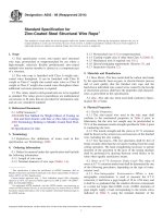
X4. FLOWCHART OF PRACTICE F1063 PROCEDURES
X4.1 See Fig. X4.1 for a flowchart outlining the procedures
in Practice F1063.
7
F1063 − 09 (2014)
FIG. X4.1 Flowchart of Practice F1063 Procedures
8
F1063 − 09 (2014)
X5. RELATED MATERIALS
X5.1.2 ISO Standards:3
ISO 5355 Ski Boots (Size Greater than 220 mm) for Ski
Bindings for Downhill Skiing Interfaces
ISO 8061 Method for the Selection of Release Torque
Values
ISO 8614 Ski Binding—Vocabulary
ISO 9462 Alpine Ski Binding Safety Requirements and Test
Methods
ISO 11088 Assembly, Adjustment, and Inspection of an
Alpine Ski-Binding-Boot System
X5.1 The following documents are either related to or
equivalent to Practice F1063.
X5.1.1 ASTM Standards:2
E456 Terminology Relating to Quality and Statistics
F473 Specification for Binding Mounting Area Dimensions
on Alpine Skis and Bindings
F504 Test Method for Measuring the Quasi-Static Release
Moments of Alpine Ski Bindings
F1062 Test Method for Verification of Ski Binding Test
Devices
3
Available from American National Standards Institute (ANSI), 25 W. 43rd St.,
4th Floor, New York, NY 10036.
ASTM International takes no position respecting the validity of any patent rights asserted in connection with any item mentioned
in this standard. Users of this standard are expressly advised that determination of the validity of any such patent rights, and the risk
of infringement of such rights, are entirely their own responsibility.
This standard is subject to revision at any time by the responsible technical committee and must be reviewed every five years and
if not revised, either reapproved or withdrawn. Your comments are invited either for revision of this standard or for additional standards
and should be addressed to ASTM International Headquarters. Your comments will receive careful consideration at a meeting of the
responsible technical committee, which you may attend. If you feel that your comments have not received a fair hearing you should
make your views known to the ASTM Committee on Standards, at the address shown below.
This standard is copyrighted by ASTM International, 100 Barr Harbor Drive, PO Box C700, West Conshohocken, PA 19428-2959,
United States. Individual reprints (single or multiple copies) of this standard may be obtained by contacting ASTM at the above
address or at 610-832-9585 (phone), 610-832-9555 (fax), or (e-mail); or through the ASTM website
(www.astm.org). Permission rights to photocopy the standard may also be secured from the Copyright Clearance Center, 222
Rosewood Drive, Danvers, MA 01923, Tel: (978) 646-2600; />
9