Astm e 1845 15
Bạn đang xem bản rút gọn của tài liệu. Xem và tải ngay bản đầy đủ của tài liệu tại đây (104.51 KB, 4 trang )
Designation: E1845 − 15
Standard Practice for
Calculating Pavement Macrotexture Mean Profile Depth1
This standard is issued under the fixed designation E1845; the number immediately following the designation indicates the year of
original adoption or, in the case of revision, the year of last revision. A number in parentheses indicates the year of last reapproval. A
superscript epsilon (´) indicates an editorial change since the last revision or reapproval.
1. Scope
3. Terminology
1.1 This practice covers the calculation of mean profile
depth from a profile of pavement macrotexture.
3.1 Definitions:
3.1.1 baselength, n—length of a segment of a pavement
macrotexture profile being analyzed, required to be 100 mm in
this practice.
3.1.2 estimated texture depth (ETD), n—estimate of the
mean texture depth (MTD), by means of a linear transformation of the mean profile depth (MPD).
3.1.3 mean profile depth (MPD), n—average of all the mean
segment depths of all of the segments of the profile.
3.1.4 mean segment depth, n—average value of the profile
depth of the two halves of a segment having a given baselength.
3.1.5 mean texture depth (MTD), n—mean depth of the
pavement surface macrotexture determined by the volumetric
technique of Test Method E965.
3.1.6 profile depth (PD), n—difference between the amplitude measurements of pavement macrotexture and a horizontal
line through the top of the highest peak within a given
baselength.
1.2 The mean profile depth has been shown to be useful in
predicting the speed constant (gradient) of wet pavement
friction.2
1.3 A linear transformation of the mean profile depth can
provide an estimate of the mean texture depth measured
according to Test Method E965.
1.4 The values stated in SI units are to be regarded as
standard. No other units of measurement are included in this
standard.
1.5 This standard does not purport to address all of the
safety concerns, if any, associated with its use. It is the
responsibility of the user of this standard to establish appropriate safety and health practices and determine the applicability of regulatory limitations prior to use.
2. Referenced Documents
2.1 ASTM Standards:3
E178 Practice for Dealing With Outlying Observations
E965 Test Method for Measuring Pavement Macrotexture
Depth Using a Volumetric Technique
2.2 ISO Standard:
ISO 13473-1 Acoustics—Characterization of Pavement
Texture using Surface Profiles–Part 1: Determination of
Mean Profile Depth4
4. Summary of Practice
4.1 This practice uses a measured profile of the pavement
macrotexture.
4.2 The measured profile is divided for analysis purposes
into segments each having a baselength of 100 mm. The slope,
if any, of each segment is suppressed by subtracting a linear
regression of the segment. The segment is further divided in
half and the height of the highest peak in each half segment is
determined. The difference between that height and the average
level of the segment is calculated. The average value of these
differences for all segments making up the measured profile is
reported as the MPD.
1
This practice is under the jurisdiction of Committee E17 on Vehicle - Pavement
Systems and is the direct responsibility of Subcommittee E17.23 on Surface
Characteristics Related to Tire Pavement Slip Resistance.
Current edition approved May 1, 2015. Published June 2015. Originally
approved in 1996. Last previous edition approved in 2009 as E1845 – 09. DOI:
10.1520/E1845-15.
2
Wambold, J. C., Antle, C. E., Henry, J. J., and Rado, Z., International PIARC
Experiment to Compare and Harmonize Texture and Skid Resistance
Measurements, Final report, Permanent International Association of Road Congresses (PIARC), Paris 1995.
3
For referenced ASTM standards, visit the ASTM website, www.astm.org, or
contact ASTM Customer Service at For Annual Book of ASTM
Standards volume information, refer to the standard’s Document Summary page on
the ASTM website.
4
Available from International Organization for Standardization (ISO), 1, ch. de
la Voie-Creuse, Case postale 56, CH-1211, Geneva 20, Switzerland, http://
www.iso.ch.
5. Significance and Use
5.1 This practice is suitable for the calculation of the
average macrotexture depth from profile data. The results of
this calculation (MPD) have proven to be useful in the
prediction of the speed dependence of wet pavement friction.2
5.2 The MPD can be used to estimate the result of a
measurement of macrotexture depth using a volumetric technique according to Test Method E965. The values of MPD and
Copyright © ASTM International, 100 Barr Harbor Drive, PO Box C700, West Conshohocken, PA 19428-2959. United States
1
E1845 − 15
MTD differ due to the finite size of the glass spheres used in the
volumetric technique and because the MPD is derived from a
two-dimensional profile rather than a three-dimensional surface. Therefore a transformation equation must be used.
6.2.2 Maximum spot size for a laser or other electro-optical
device shall be no greater than 1 mm. The stylus in a contact
device shall have a tip having a major diameter no greater than
1 mm.
6.2.3 The sampling interval shall not be more than 1 mm.
Variations of the sampling interval shall not be more than
610 %. This requires that the sensor speed over the surface be
maintained within 610 % whether the device is stationery or
mounted on a moving vehicle.
5.3 This practice may be used with pavement macrotexture
profiles taken on actual road surfaces or from cores or
laboratory prepared samples.
5.4 Aggregate size, shape, and distribution are features
which are not addressed in this practice. This practice is not
meant to provide a complete assessment of texture characteristics. In particular, care should be used when interpreting the
result for porous or grooved surfaces.
6.3 The angles between the radiating emitting device and
the surface and between the radiation receiving device and the
surface shall be no more than 30°. The angle of the stylus
relative to the surface shall be no more than 30°. Larger angles
will underestimate deep textures.
5.5 This practice does not address the problems associated
with obtaining a measured profile. Laser or other optical
noncontact methods of measuring profiles are usually preferred. However, contact methods using a stylus also can
provide accurate profiles if properly performed.
6.4 Calibration shall be made using calibration surfaces
having a known profile. The vertical accuracy of the calibration
surface in relation to its theoretical profile shall be at least 0.05
mm. The calibration shall be designed to provide a maximum
error of 5 % or 0.1 mm, whichever is lower.
6. Profile Requirements
6.1 Amount of Data Required:
6.1.1 Ideally, a continuous profile made along the entire
length of the test section should be used if possible.
6.1.2 A minimum requirement shall be ten evenly spaced
profiles of 100 mm in length for each 100 m of the test section.
However, for a uniform test section, it is sufficient to obtain 16
evenly spaced profiles regardless of test section length. For
surfaces having periodic texture (that is, grooved or tined
surfaces) the total profile length shall include at least ten
periods of the texture.
NOTE 5—One suitable calibration surface is a surface machined to
obtain a triangular profile with a peak-to-peak amplitude of 5 to 20 mm.
This gives an indication of not only the amplitude, but also the nonlinearity and the texture wavelength scale.
7. Data Processing
7.1 Outliers—Invalid readings may be caused by dropouts
as a result of deep surface troughs or local photometric
properties of the surface. For this reason, those readings should
be eliminated when their value is higher or lower than the
range of the profile surrounding their location. The invalid
value for that location shall be replaced with a value interpolated between the previous and following location. The maximum proportion of outliers shall be 20 %. When the proportion
exceeds 10 %, caution should be used in interpreting the data
and the proportion of invalid readings shall be reported. Use
Practice E178 to determine what data is to be considered an
outlier.
NOTE 1—Inspect the pavement surface to be measured and ensure that
it is dry. When possible, thoroughly clean the surface using compressed air
or a soft-bristle brush, or both, in order to remove any visible residue,
debris, or loose aggregate particles from the surface. When characterizing
a long test section with relatively short sample lengths, it is important to
ensure that the texture is sufficiently homogeneous to provide a representative measure. It is necessary for the user to use sound judgment to
determine the minimum number of samples to characterize a nonhomogeneous pavement.
NOTE 2—The texture of pavements that have been in service varies
across the pavement. In this case the transverse location of the measurements shall be determined by the intended use of the data.
7.2 Lowpass Filtering—To reduce the influence of noise and
transients and to have a relatively uniform influence of narrow
profile peaks, the profile shall be filtered to remove high
frequency components. Spatial frequency components above
400 cycles per metre that correspond to a texture wavelength of
2.5 mm shall be removed. Spatial frequencies below 200 cycles
per metre that correspond to a texture wavelength of 5 mm
shall not be affected by the filter. Attenuation shall be at
least − 3 dB at 2.5 mm and no more than − 1 dB at 5 mm with
a slope of at least − 6 dB per octave. The filtering may be
achieved with a digital filter or with an electronic filter. All or
part of the filtering may be achieved by the effect of the finite
size of the sensor spot or stylus tip.
6.1.3 In the case of laboratory samples (either cores or
rectangular slabs) the minimum requirement shall be at least
ten profiles having a length of 100 mm evenly distributed over
the surface of the sample. Care should be taken to avoid edge
effects. For this reason, samples having a characteristic length
of at least 150 mm are recommended.
NOTE 3—Measurements on laboratory samples have many different
purposes. Therefore it is difficult to specify general minimum requirements. The specification here assumes that the purpose is to obtain values
which are reasonably representative of pavements.
6.2 Resolution:
6.2.1 Vertical resolution shall be at least 0.05 mm. Vertical
range shall be no less than 20 mm and vertical nonlinearity
shall be no greater than 2 % of the range.
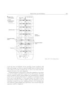
7.3 Segmenting the Profile—The measured profile shall be
divided into segments of 100 6 2 mm for analysis in the
subsequent steps of this practice. See Fig. 1.
NOTE 4—For stationary devices on smooth pavements a lesser range
may be used. In this case, non-linearity need not exceed the above
requirement of 0.4 mm. The higher range is usually required to allow for
a sensor mounted on a moving vehicle.
7.4 Slope Suppression—A linear regression of the profile
values for each segment shall be performed and the regression
line shall be subtracted from the profile values of the segment.
2
E1845 − 15
FIG. 1 Procedure for Computation of Mean Segment Depth
8.1.3 Description of the surface type;
8.1.4 Description of surface contamination that could not be
avoided by cleaning, including moisture;
8.1.5 Observations of surface condition such as excessive
cracking, potholes, and so forth;
8.1.6 The position of the profile on the surface, for example
in relation to the wheel track, and so forth;
8.1.7 Identification of the profile equipment and its operators;
8.1.8 Type and date of calibration;
8.1.9 Measurement speed;
8.1.10 Percentage of invalid readings eliminated (dropouts);
8.1.11 Total profile length and the number of segments
analyzed;
8.1.12 Mean profile depth (MPD);
8.1.13 Standard deviation of the mean segment depths
which were averaged to obtain the MPD; and
8.1.14 The estimated texture depth (ETD)—optional.
This will produce a segment with a zero mean and suppress the
slope of the segment, if any.
7.5 Peak Determination—Each segment shall be further
divided into two equal lengths of 50 mm and the maximum
value of the profile shall be determined for each of the 50-mm
subsegments. These two values shall be averaged arithmetically to obtain the mean segment depth. See Fig. 1.
NOTE 6—Some devices invert the profile so that it is necessary to ensure
that the profile for the segment being analyzed has the peaks as those
asperities with the highest positive value.
7.6 Determination of MPD—The average value of the mean
segment depths for all segments of the measured profile shall
be averaged to obtain the mean profile depth (MPD).
7.7 Calculation of ETD (optional)—The MPD may be
transformed to an estimated texture depth (ETD) by use of the
following transformation equation:2
ETD 5 0.210.8 MPD
(1)
where:
MPD and ETD are expressed in mm.
The use of this transformation should yield ETD values that
are close to the MTD values of the volumetric technique
according to Test Method E965. However, caution should be
used in the comparison of ETD (that does not capture the
concave recesses of the pavement surface) to MTD (that does
capture the concave recesses in the pavement surface).
9. Precision and Bias
9.1 Precision—The reproducibility using two different systems and test crews was found in the same experiment2 to be
0.15 mm corresponding to 10 % of the average MPD values
included in the experiment.
9.2 Bias—There is no basis for determination of the bias in
mean profile depth. With respect to the MTD, the MPD is
biased by 0.2 mm that is due to the finite size of the glass
spheres used in the volumetric technique.
8. Report
8.1 The test report for each test surface shall contain the
following items:
8.1.1 Date of profile measurement;
8.1.2 Location and identification of the test surface;
10. Keywords
10.1 macrotexture profile; mean profile depth; mean texture
depth
3
E1845 − 15
ASTM International takes no position respecting the validity of any patent rights asserted in connection with any item mentioned
in this standard. Users of this standard are expressly advised that determination of the validity of any such patent rights, and the risk
of infringement of such rights, are entirely their own responsibility.
This standard is subject to revision at any time by the responsible technical committee and must be reviewed every five years and
if not revised, either reapproved or withdrawn. Your comments are invited either for revision of this standard or for additional standards
and should be addressed to ASTM International Headquarters. Your comments will receive careful consideration at a meeting of the
responsible technical committee, which you may attend. If you feel that your comments have not received a fair hearing you should
make your views known to the ASTM Committee on Standards, at the address shown below.
This standard is copyrighted by ASTM International, 100 Barr Harbor Drive, PO Box C700, West Conshohocken, PA 19428-2959,
United States. Individual reprints (single or multiple copies) of this standard may be obtained by contacting ASTM at the above
address or at 610-832-9585 (phone), 610-832-9555 (fax), or (e-mail); or through the ASTM website
(www.astm.org). Permission rights to photocopy the standard may also be secured from the Copyright Clearance Center, 222
Rosewood Drive, Danvers, MA 01923, Tel: (978) 646-2600; />
4