Astm e 1274 03 (2017)
Bạn đang xem bản rút gọn của tài liệu. Xem và tải ngay bản đầy đủ của tài liệu tại đây (224.01 KB, 4 trang )
This international standard was developed in accordance with internationally recognized principles on standardization established in the Decision on Principles for the
Development of International Standards, Guides and Recommendations issued by the World Trade Organization Technical Barriers to Trade (TBT) Committee.
Designation: E1274 − 03 (Reapproved 2017)
Standard Test Method for
Measuring Pavement Roughness Using a Profilograph1
This standard is issued under the fixed designation E1274; the number immediately following the designation indicates the year of
original adoption or, in the case of revision, the year of last revision. A number in parentheses indicates the year of last reapproval. A
superscript epsilon (´) indicates an editorial change since the last revision or reapproval.
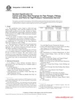
lows of the surface record depicting at least 100 ft (30 m) of
pavement (see Fig. 2).
3.1.2 cutoff height—a specified distance of a high on the
surface record from a chord representing 25 ft (7.5 m) on the
longitudinal scale. The chord may represent less than 25 ft
(7.5 m) if it is from the lows on each side of the high (see Fig.
2).
3.1.3 rate of roughness—sum of the roughness divided by
the longitudinal distance covered by the blanking band.
3.1.4 roughness—height of each continuous scallop rounded
to the nearest 0.05 in. (1 mm), except those less than 0.03 in.
(0.8 mm) vertically and 2 ft (0.6 m) longitudinally.
3.1.5 scallops—excursions of the surface record above and
below the blanking band (see Fig. 2).
1. Scope
1.1 This test method covers the measurement of pavement
roughness using an articulated multi-wheeled profilograph at
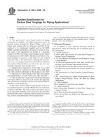
least 23 ft (7 m) long (Fig. 1 is typical).
1.2 This test method utilizes a surface record made by
moving the profilograph longitudinally over the pavement at
less than 3 mph (5 km/hr). The record is analyzed to determine
the rate of roughness and to identify bumps that exceed a
specified threshold.
1.3 The values stated in inch-pound units are to be regarded
as standard. The values given in parentheses are mathematical
conversions to SI units that are provided for information only
and are not considered standard.
1.4 This standard does not purport to address all of the
safety problems, if any, associated with its use. It is the
responsibility of the user of this standard to establish appropriate safety and health practices and determine the applicability of regulatory limitations prior to use. See Section 6 for
specific hazard statement.
1.5 This international standard was developed in accordance with internationally recognized principles on standardization established in the Decision on Principles for the
Development of International Standards, Guides and Recommendations issued by the World Trade Organization Technical
Barriers to Trade (TBT) Committee.
4. Significance and Use
4.1 This test method provides a means for measuring the
roughness of new or rehabilitated pavements. Results may
differ between profilographs of different designs and therefore
will not necessarily agree with roughness measurements by
other profilographs or other roughness-measuring equipment.
5. Apparatus
5.1 Profilographs:
5.1.1 With Uniformly Spaced Wheels—A reference platform
comprised of dollies articulated by rigid members or trusses so
that all the wheels are supporting the profilograph. There must
be at least twelve reference platform wheels, and the axes of
these wheels must be uniformly spaced throughout the effective length of the profilograph.3 The effective length must be at
least 23 ft (7 m) long. A surface sensing wheel and recorder
shall be located at the center of the reference platform. The
diameter of the surface sensing wheel shall be at least 6 in.
(150 mm). If the recorder is graphic, its scales shall be 1:1
vertically and 1:300 longitudinally (1 in. = 25 ft). If the
recorder is digital (optional analog display must have the same
scales as the graphic recorder), it must sample 5 times/
longitudinal inch of travel and record the relative height of the
surface to at least the nearest 0.01 in. (0.25 mm).
2. Referenced Documents
2.1 ASTM Adjuncts:
Blueprint of California Profilograph Assembly (18 blueprints)2
3. Terminology
3.1 Definitions of Terms Specific to This Standard:
3.1.1 blanking band—a band of uniform height with its
longitudinal center positioned optimally between the highs and
1
This test method is under the jurisdiction of ASTM Committee E17 on Vehicle
- Pavement Systems and is the direct responsibility of Subcommittee E17.31 on
Methods for Measuring Profile and Roughness.
Current edition approved June 1, 2017. Published June 2017. Originally
approved in 1988. Last previous edition approved in 2012 as E1274 – 03 (2012).
DOI: 10.1520/E1274-03R17.
2
Available from ASTM International Headquarters. Order Adjunct No.
ADJE1274.
3
Hankins, Kenneth D., “Construction Control Profilograph Principles,” Research Report 49-1, Texas Highway Department, June 1967.
Copyright © ASTM International, 100 Barr Harbor Drive, PO Box C700, West Conshohocken, PA 19428-2959. United States
1
E1274 − 03 (2017)
FIG. 1 Typical Profilograph
proper traffic control devices and use procedures that assure the
safety of testing personnel and the public.
7. Sampling
7.1 Take profilograph recordings 3.5 6 0.5 ft (1.0 6 0.2 m)
from and parallel to both edges of the pavement and to both
sides of each planned longitudinal joint or in each planned
wheel path.
NOTE 1—Fig. 2 is graphic for visual reading. It can be digital for
computer input.
FIG. 2 Surface Record
5.1.2 With Non-Uniformly Spaced Wheels—It shall be as
described in 5.1.1, except the axes of the reference-platform
wheels are not uniformly spaced but are at least 1 ft (0.3 m)
apart so no two wheels cross the same bump at the same time.
The recorder can be located elsewhere, but surface sensing
equipment must be located at the center of the reference
platform. A common apparatus with non-uniformly spaced
wheels is the California profilograph (see 2.1).
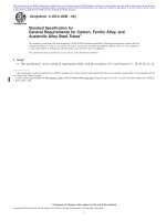
5.1.3 There are differences in frequency responses between
profilographs with uniformly spaced wheels and profilographs
with non-uniformly spaced wheels (see Fig. 3).
7.2 Any exceptions to these sampling requirements (for
example, 25 ft from each bridge) must be stipulated.
8. Calibration
8.1 Height Recording:
8.1.1 Place gauge blocks of 0.5 in. (10 mm) and 1.5 in.
(60 mm) under the surface sensing wheel. The record must
indicate the actual height of each platform within 60.02 in.
(0.5 mm).
8.1.2 Verify the standardization of the height recording
before any week of use, whenever the profilograph is reassembled and whenever there is evidence of possible inaccuracy.
5.2 Blanking Band Template (optional)—Approximately
2-in. (50-mm) wide clear plastic strip at least 4 in. (100 mm)
long. A common length is 21.12 in. The center of the template
is marked with an opaque strip the width of the stipulated
blanking band throughout its length and with lines every 0.1 in.
(2 mm) above and below the blanking band.
8.2 Distance Recording:
8.2.1 Mark a distance of 100.00 ft (30.00 m) on reasonably
even pavement. Move the profilograph forward until a particular point is at the first mark and make the recorder mark the
event on the record. Move the profilograph forward again until
the point is at the second mark and make the recorder to mark
this event, too. The record must indicate 100 6 1 ft (30.0 6
0.3 m) between the two events (4.00 6 0.04 in. on graphic
record).
8.2.2 Verify the standardization of the distance recording
before any month of use and whenever there is evidence of
possible inaccuracy.
5.3 Excessive Height Template (optional)—Clear plastic
piece marked with a 1.00 6 0.02-in. (25.0 6 0.5-mm) line that
is the stipulated cutoff height distance from a straight edge on
the template. Two small holes may be drilled to fix the ends of
the line (see Fig. 2).
6. Hazards
6.1 Since profilographs in the testing mode are moved no
faster than 3 mph (5 km/hr), do not operate near traffic without
2
E1274 − 03 (2017)
NOTE 1—This figure comes from Walker, Roger S., and H.-T. Lin, The University of Texas at Arlington, Research Project 8-10-87-569, “Correlation
of California and Rainhart Profilographs with PSI,” conducted for Texas State Department of Highways and Public Transportation in cooperation with
the U.S. Department of Transportation, Federal Highway Administration.
FIG. 3 Computer Simulation of Profilograph Responses to Sinusoidal Inputs of Different Periods (wave lengths)
9. Procedure
10.1 Apply the blanking band to successive lengths of the
surface record. Determine the roughness from each scallop.
Add all roughness for each stipulated segment. From the
surface record, determine the longitudinal distance between the
farthest points of the beginning and ending scallops or absence
thereof. Divide the result of the addition by the corresponding
longitudinal distance to calculate the rate of roughness for that
segment of that path.
9.1 Clear the intended profilograph path of all loose material
and foreign objects.
9.2 If possible, move the profilograph about 30 ft (10 m)
forward to the starting point. Once there, initialize the recorder
and make beginning notations.
9.3 Move the profilograph forward no faster than 3 mph
(5 km ⁄hr), steering it to stay within that prescribed sampling
path. Pertinent observation about surveyed location or unusual
conditions may be made on the record only as they occur.
Observe the recorder for any unusual operation.
10.2 Apply the excessive height chord to the top of each
wave on the surface record. Identify all bumps that are
excessively high by their locations.
11. Report
9.4 Upon completion of a sampling path, make ending
notations and review the recording for reasonableness. Repeat
the procedure for successive sampling paths.
11.1 The following information shall be given for each
specific application:
11.1.1 Height of blanking band to nearest 0.05 in. (1 mm),
(for example, 0.1 or 0.2 in.),
11.1.2 Cutoff height to the nearest 0.05 in. (1 mm), (for
example, 0.3 in.),
10. Calculation
NOTE 1—Calculations can be done manually with the blanking band
and excessive height templates or electronically with routines in a
computer.
3
E1274 − 03 (2017)
11.1.3 Profilograph with or without uniformly spaced reference platform wheels, and
11.1.4 Length of each segment for which the rate of
roughness is calculated.
13. Keywords
13.1 graphic surface record; pavement; roughness
12. Precision and Bias
12.1 The precision and bias of this test method are being
determined.
ASTM International takes no position respecting the validity of any patent rights asserted in connection with any item mentioned
in this standard. Users of this standard are expressly advised that determination of the validity of any such patent rights, and the risk
of infringement of such rights, are entirely their own responsibility.
This standard is subject to revision at any time by the responsible technical committee and must be reviewed every five years and
if not revised, either reapproved or withdrawn. Your comments are invited either for revision of this standard or for additional standards
and should be addressed to ASTM International Headquarters. Your comments will receive careful consideration at a meeting of the
responsible technical committee, which you may attend. If you feel that your comments have not received a fair hearing you should
make your views known to the ASTM Committee on Standards, at the address shown below.
This standard is copyrighted by ASTM International, 100 Barr Harbor Drive, PO Box C700, West Conshohocken, PA 19428-2959,
United States. Individual reprints (single or multiple copies) of this standard may be obtained by contacting ASTM at the above
address or at 610-832-9585 (phone), 610-832-9555 (fax), or (e-mail); or through the ASTM website
(www.astm.org). Permission rights to photocopy the standard may also be secured from the Copyright Clearance Center, 222
Rosewood Drive, Danvers, MA 01923, Tel: (978) 646-2600; />
4