E 499 e 499m 11 (2017)
Bạn đang xem bản rút gọn của tài liệu. Xem và tải ngay bản đầy đủ của tài liệu tại đây (153.48 KB, 6 trang )
This international standard was developed in accordance with internationally recognized principles on standardization established in the Decision on Principles for the
Development of International Standards, Guides and Recommendations issued by the World Trade Organization Technical Barriers to Trade (TBT) Committee.
Designation: E499/E499M − 11 (Reapproved 2017)
Standard Practice for
Leaks Using the Mass Spectrometer Leak Detector in the
Detector Probe Mode1,2
This standard is issued under the fixed designation E499/E499M; the number immediately following the designation indicates the year
of original adoption or, in the case of revision, the year of last revision. A number in parentheses indicates the year of last reapproval.
A superscript epsilon (´) indicates an editorial change since the last revision or reapproval.
This standard has been approved for use by agencies of the U.S. Department of Defense.
2. Referenced Documents
1. Scope
2.1 ASTM Standards:4
E1316 Terminology for Nondestructive Examinations
2.2 Other Documents:
SNT-TC-1A Recommended Practice for Personnel Qualification and Certification in Nondestructive Testing5
ANSI/ASNT CP-189 ASNT Standard for Qualification and
Certification of Nondestructive Testing Personnel5
1.1 This practice covers procedures for testing and locating
the sources
of gas leaking at the rate of 1 × 10⁻⁷ Pa m3/s
−8
(1 × 10 Std cm3/s)3 or greater. The test may be conducted on
any device or component across which a pressure differential
of helium or other suitable tracer gas may be created, and on
which the effluent side of the leak to be tested is accessible for
probing with the mass spectrometer sampling probe.
1.2 Two test methods are described:
1.2.1 Test Method A—Direct probing, and
1.2.2 Test Method B—Accumulation.
3. Terminology
3.1 Definitions—For definitions of terms used in this
standard, see Terminology E1316, Section E.
1.3 Units—The values stated in either SI or std-cc/sec units
are to be regarded separately as standard. The values stated in
each system may not be exact equivalents: therefore, each
system shall be used independently of the other. Combining
values from the two systems may result in non-conformance
with the standard.
4. Summary of Practice
4.1 Section 1.8 of the Leakage Testing Handbook6 will be of
value to some users in determining which leak test method to
use.
4.2 The test methods covered in this practice require a leak
detector−7 with a full-scale readout of at least 1 × 10⁻⁶ Pa m3/s
(1 × 10 Std cm3/s)3 on the most sensitive range, a maximum
1-min drift of zero and sensitivity of 65 % of full scale on this
range, and 62 % or less on others (see 7.1). The above
sensitivities are those obtained by probing an actual standard
leak in atmosphere with the detector, or sampling, probe, and
not the sensitivity of the detector to a standard leak attached
directly to the vacuum system.
1.4 This standard does not purport to address all of the
safety concerns, if any, associated with its use. It is the
responsibility of the user of this standard to establish appropriate safety and health practices and determine the applicability of regulatory limitations prior to use.
1.5 This international standard was developed in accordance with internationally recognized principles on standardization established in the Decision on Principles for the
Development of International Standards, Guides and Recommendations issued by the World Trade Organization Technical
Barriers to Trade (TBT) Committee.
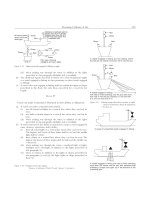
4.3 Test Method A, Direct Probing (see Fig. 1), is the
simplest test, and may be used in parts of any size, requiring
only that a tracer gas pressure be created across the area to be
tested, and the searching of the atmospheric side of the area be
with the detector probe. This test method detects leakage and
1
This practice is under the jurisdiction of ASTM Committee E07 on Nondestructive Testing and is the direct responsibility of Subcommittee E07.08 on Leak
Testing Method.
Current edition approved June 1, 2017. Published July 2017. Originally approved
in 1973. Last previous edition approved in 2011 as E499 - 11. DOI: 10.1520/E0499
_E0499M-11R17.
2
(Atmospheric pressure external, pressure above atmospheric internal). This
document covers the Detector Probe Mode described in Guide E432.
3
The gas temperature is referenced to 0°C. To convert to another gas reference
temperature, Tref, multiply the leak rate by (Tref + 273) ⁄273.
4
For referenced ASTM standards, visit the ASTM website, www.astm.org, or
contact ASTM Customer Service at For Annual Book of ASTM
Standards volume information, refer to the standard’s Document Summary page on
the ASTM website.
5
Available from American Society for Nondestructive Testing (ASNT), P.O. Box
28518, 1711 Arlingate Ln., Columbus, OH 43228-0518, .
6
Marr, J. William, “Leakage Testing Handbook,” prepared for Liquid Propulsion
Section, Jet Propulsion Laboratory, National Aeronautics and Space Administration,
Pasadena, CA, Contract NAS 7-396, June 1961.
Copyright © ASTM International, 100 Barr Harbor Drive, PO Box C700, West Conshohocken, PA 19428-2959. United States
1
E499/E499M − 11 (2017)
FIG. 1 Method A
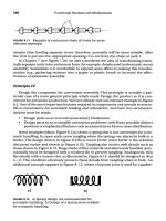
FIG. 2 Method B
tions against releasing gas like the tracer gas in the test area are
observed, and the effects of other interferences (Section 6) are
considered.
its source or sources. Experience has shown that leak testing
down to 1 × 10⁻⁵ Pa m3/s (1 × 10⁻⁶ Std cm3/s)3 in factory
environments will usually be satisfactory if reasonable precau2
E499/E499M − 11 (2017)
plastics) may be released during the test. If the rate and
magnitude of the amount released approaches the amount
released from the leak, the reliability of the test is decreased.
The amount of such materials or their exposure to helium must
then be reduced to obtain a meaningful test.
4.4 Test Method B, Accumulation Testing (see Fig. 2),
provides for the testing of parts up to several cubic metres in
volume as in Fig. 2(a) or in portions of larger devices as in Fig.
2(b). This is accomplished by allowing the leakage to accumulate in the chamber for a fixed period, while keeping it well
mixed with a fan, and then testing the internal atmosphere for
an increase in tracer gas content with the detector probe. The
practical sensitivity attainable with this method depends primarily on two things: first, on the volume between the chamber
and the object; and second, on the amount of outgassing of
tracer gas produced by the object. Thus, a part having considerable exposed rubber, plastic, blind cavities or threads cannot
be tested with the sensitivity of a smooth metallic part. The
time in which a leak can be detected is directly proportional to
the leak rate and inversely proportional to the volume between
the chamber and the part. In theory, extremely small leaks can
be detected by this test method; however, the time required and
the effects of other interferences limit the practical sensitivity
of this test method to about 1 × 10⁻⁷ Pa m3/s (1 × 10⁻⁸ Std
cm3/s)3 for small parts.
7.3 Pressurizing with Test Gas—In order to evaluate leakage
accurately, the test gas in all parts of the device must contain
substantially the same amount of tracer gas. When the device
contains air prior to the introduction of test gas, or when an
inert gas and a tracer gas are added separately, this may not be
true. Devices in which the effective diameter and length are not
greatly different (such as tanks) may be tested satisfactorily by
simply adding tracer gas. However, when long or restricted
systems are to be tested, more uniform tracer distribution will
be obtained by first evacuating to less than 100 Pa (a few torr),
and then filling with the test gas. The latter must be premixed
if not 100 % tracer.
7.4 Dirt and Liquids—As the orifice in the detector probe is
very small, the parts being tested should be clean and dry to
avoid plugging. Reference should be frequently made to a
standard leak to ascertain that this has not happened.
5. Personnel Qualification
5.1 It is recommended that personnel performing leak testing attend a dedicated training course on the subject and pass
a written examination. The training course should be appropriate for NDT level II qualification according to Recommended
Practice No. SNT-TC-1A of the American Society for Nondestructive Testing or ANSI/ASNT Standard CP-189.
8. Apparatus,
8.1 Helium Leak Detector, equipped with atmospheric detector probe. To perform tests as specified in this standard, the
detector should be adjusted for testing with helium and should
have the following minimum features:
8.1.1 Sensor Mass Analyzer.
8.1.2 Readout, analog or digital.
8.1.3 Range (linear)—A signal equivalent to 1 × 10⁻⁵ Pa
3
m /s (1 × 10⁻⁶ Std cm3/s)3 or larger must be detectable.
8.1.4 Response time, 3 s or less.
8.1.5 Stability of Zero and Sensitivity— A maximum variation of 65 % of full scale on the most sensitive range while the
probe is active; a maximum variation of 62 % of full scale on
other ranges for a period of 1 min.
6. Significance and Use
6.1 Test Method A is frequently used to test large systems
and complex piping installations that can be filled with a trace
gas. Helium is normally used. The test method is used to locate
leaks but cannot be used to quantify except for approximation.
Care must be taken to provide sufficient ventilation to prevent
increasing the helium background at the test site. Results are
limited by the helium background and the percentage of the
leaking trace gas captured by the probe.
NOTE 1—Variations may be a function of environmental interferences
rather than equipment limitations.
6.2 Test Method B is used to increase the concentration of
trace gas coming through the leak by capturing it within an
enclosure until the signal above the helium background can be
detected. By introducing a calibrated leak into the same
volume for a recorded time interval, leak rates can be measured.
8.1.6 Controls:
8.1.6.1 Range, preferable in scale steps of 10×.
8.1.6.2 Zero, having sufficient range to null out atmospheric
helium.
8.2 Helium Leak Standard—To perform leak tests as specified in this standard (system calibration), the leak standard
should meet the following minimum requirements:
8.2.1 Ranges—1 × 10⁻² to 1 × 10⁻⁶ Pa m3/s (10−3 to 10−7
Std cm3/s)3 full scale calibrated for discharge to atmosphere.
8.2.2 Adjustability—Adjustable leak standards are a convenience but are not mandatory.
8.2.3 Accuracy, 615 % of full-scale value or better.
8.2.4 Temperature Coeffıcient, shall be stated by manufacturer.
7. Interferences,
7.1 Atmospheric Helium—The atmosphere contains about
five parts per million (ppm) of helium, which is being
continuously drawn in by the detector probe. This background
must be “zeroed out” before leak testing using helium can
proceed. Successful leak testing is contingent on the ability of
the detector to discriminate between normal atmospheric
helium, which is very constant, and an increase in helium due
to a leak. If the normally stable atmospheric helium level is
increased by release of helium in the test area, the reference
level becomes unstable, and leak testing more difficult.
8.3 Helium Leak Standard, as in 8.2 but with ranges of
1 × 10⁻⁵ Pa m3/s or 1 × 10⁻⁸ Pa m3/s (10−6 or 10−9 Std cm3/s)
full scale calibrated for discharge to vacuum shall be used for
instrument calibration.3
7.2 Helium Outgassed from Absorbent Materials—Helium
absorbed in various nonmetallic materials (such as rubber or
3
E499/E499M − 11 (2017)
11.1.2 Safety Factor—Where feasible, it should be ascertained that a reasonable safety factor has been allowed between
the actual operational requirements of the device and the
maximum specified for testing. Experience indicates that a
factor of at least 10 should be used when possible. For
example, if a maximum total leak rate for satisfactory operation of a device is 5 × 10⁻⁵ Pa m3/s (5 × 10⁻⁶ Std cm3/s)3, the
test requirement should be 5 × 10⁻⁶ Pa m3/s (5 × 10⁻⁷ Std
cm3/s)3 or less.
11.1.3 Test Pressure—The device should be tested at or
above its operating pressure and with the pressure drop in the
normal direction, where practical. Precautions should be taken
so that the device will not fail during pressurization, or that the
operator is protected from the consequences of a failure.
11.1.4 Disposition or Recovery of Test Gas—Test gas should
never be dumped into the test area if further testing is planned.
It should be vented outdoors or recovered for reuse if the
volume to be used makes this worthwhile.
11.1.5 Detrimental Effects of Helium Tracer Gas—This gas
is quite inert, and seldom causes any problems with most
materials, particularly when used in gaseous form for leak
testing and then removed. When there is a question as to the
compatibility of the tracer with a particular material, an
authority on the latter should be consulted. This is particularly
true when helium is sealed in contact with glass or other
barriers that it may permeate.
11.1.6 Correlation of Test Gas Leakage with Other Gases or
Liquids at Different Operating Pressures:
11.1.6.1 Given the normal variation in leak geometry, accurate correlation is an impossibility. However, if a safety factor
of ten or more is allowed, in accordance with 11.1.2, adequate
correlation for gas leakage within these limits can usually be
obtained by assuming viscous flow and using the equation:
8.4 Other Apparatus—Fixtures or other equipment specific
to one test method are listed under that test method.
9. Material
9.1 Test Gas Requirements:
9.1.1 To be satisfactory, the test gas shall be nontoxic,
nonflammable, not detrimental to common materials, and
inexpensive. Helium, or helium mixed with air, nitrogen, or
some other suitable inert gas meets the requirements. If the test
specification allows leakage of 1 × 10⁻⁴ Pa m3/s (1 × 10⁻⁵ Std
cm3/s)3 or more, or if large vessels are to be tested, consideration should be given to diluting the tracer gas with another gas
such as dry air or nitrogen. This will avoid excessive helium
input to the sensor and in the case of large vessels, save tracer
gas expense (Note 2).
9.1.2 Producing Premixed Test Gas—If the volume of the
device or the quantity to be tested is small, premixed gases can
be conveniently obtained in cylinders. The user can also mix
gases by batch in the same way. Continuous mixing using
calibrated orifices is another simple and convenient method
when the test pressure does not exceed 50 % of the tracer gas
pressure available.
NOTE 2—When a vessel is not evacuated prior to adding test gas, the
latter is automatically diluted by one atmosphere of air.
9.2 Liquid Nitrogen, or other means of cold trap refrigeration as specified by the maker of the leak detector.
10. Calibration,
10.1 The leak detectors used in making leak tests by these
test methods are not calibrated in the sense that they are taken
to the standards laboratory, calibrated, and then returned to the
job. Rather, the leak detector is used as a comparator between
a leak standard (8.2) (set to the specified leak size) which is
part of the instrumentation, and the unknown leak. However,
the sensitivity of the leak detector is checked and adjusted on
the job so that a leak of specified size will give a readily
observable, but not off-scale reading. More specific details are
given in Section 11 under the test method being used. To verify
sensitivity, reference to the leak standard should be made
before and after a prolonged test. When rapid repetitive testing
of many items is required, refer to the leak standard often
enough to ensure that desired test sensitivity is maintained.
Q 2 5 ~ Q 1 N 1 /N 2 ! @ ~ P
where:
Q2
Q1
N2
N1
P2, P1
P4, P3
=
=
=
=
=
=
2
2
2 P 1 2! / ~ P
2
4
2 P 3 2! #
test leakage, Pa·m3/s (standard cm3/s),
operational leakage, Pa·m3/s (standard cm3/s),
viscosity of test gas (Note 3),
viscosity of operational gas (Note 3),
absolute pressures on high and low sides at test, and
absolute pressures on high and low sides in operation (Note 4).
11.1.6.2 Experience has shown that, at the same pressures,
gas leaks smaller than 1 × 10⁻⁴ Pa m3/s (1 × 10⁻⁵ Std cm3/s)3
will not show visible leakage of a liquid, such as water, which
evaporates fairly rapidly. For slowly evaporating liquids such
as lubricating oil, the gas leakage should be another order of
magnitude smaller, 1 × 10⁻⁵ Pa m3/s (1 × 10⁻⁶ Std cm3/s).3 See
Santeler and Moller7 for further discussion of this topic.
11. Procedure
11.1 General Considerations:
11.1.1 Test Specifications—A testing specification shall be
in hand. This shall include:
11.1.1.1 The gas pressure on the high side of the device to
be tested; also on the low side if it need differ from atmospheric
pressure.
11.1.1.2 The test gas composition, if there is need to specify
it.
11.1.1.3 The maximum allowable leak rate in standard cubic
centimetres per second.
11.1.1.4 Whether the leak rate is for each leak or for total
leakage of the device.
11.1.1.5 If an “each leak” specification, whether or not other
than seams, joints, and fittings needs to be tested.
NOTE 3—Viscosity differences between gases are a relatively minor
effect and can be ignored if desired.
NOTE 4—It will be observed from this equation that the leakage
increases at a rate considerably greater than that of the pressure increase.
For this reason it is often desirable to increase the sensitivity of the test by
7
Santeler, D. J., and Moller, T. W., “Fluid Flow Conversion in Leaks and
Capillaries,” Vacuum Symposium Transactions , Pergamon Press, London, 1956, p
29. Also General Electric Company Report R56GL261.
4
E499/E499M − 11 (2017)
11.2.2.8 System calibration shall be performed prior to,
upon completion of, and during testing at intervals not to
exceed 1 h. Failure of a calibration check to obtain the same or
greater response as the previous check shall require that an
evaluation or retest of all tested parts or areas examined be
performed.
11.2.2.9 Evacuate (if required) and apply test gas to device
at specified pressure and concentration.
11.2.2.10 Probe Areas Suspected of Leaking— Probe shall
be held on or not more than 1 mm (0.04 in.) from the surface
of the device, and moved not faster than 20 mm/s (0.8 in./s). If
leaks are located which cause a “reject” indication they must be
repaired before making final acceptance test.
11.2.2.11 Maintain an orderly procedure in probing the
required areas, preferably identifying them as tested, and
plainly indicating points of leakage.
11.2.2.12 At completion of the test evacuate or purge test
gas from the device, if required.
11.2.2.13 Write a test report or otherwise indicate test
results as required.
testing at the maximum safe pressure for the part. Increased sensitivity
may even be obtained with the same amount of helium by increasing the
pressure with another less expensive gas, such as air.
11.2 Test Method A (refer to 4.3 and Fig. 1):
11.2.1 Apparatus:
11.2.1.1 Test Specification.
11.2.1.2 Helium Leak Detector, with atmospheric detector,
sampling probe.
11.2.1.3 Helium Leak Standard, discharge to atmosphere.
Size equal to helium content of maximum leak rate per
specification.
11.2.1.4 Helium Leak Standard, discharge to vacuum. Size:
anywhere between 1 × 10⁻⁵ Pa m3/s (1 × 10⁻⁶ Std cm3/s)3 and
1 × 10⁻⁸ Pa m3/s (1 × 10⁻⁹ Std cm3/s),3 unless otherwise
specified by maker of leak detector.
11.2.1.5 Test Gas, at or above specification pressure.
11.2.1.6 Pressure Gauges, Valves, and Piping, for introducing test gas, and if required, vacuum pump for evacuating
device.
11.2.1.7 Liquid Nitrogen, if required.
11.2.2 Procedure:
11.2.2.1 Set helium leak standard at maximum helium
content of specification leakage. The value of the standard leak
to be used is determined by the following formula:
CL 5 LRacc 3 %C/100
NOTE 5—If necessary to obtain a reasonable instrument deflection,
adjust range, rezero if necessary, and reapply sampling probe to leak
standard.
11.3 Test Method B (refer to 4.4 and Fig. 2):
11.3.1 Apparatus—Same as for Test Method A, except that
equipment for enclosing all or part of the item to be tested is
required as shown in Fig. 2. The size of the helium leak
standard will normally be in the range of 1 × 10⁻⁶ to 1 × 10⁻⁷
Pa m3/s (10–7 to 10–8 Std cm3/s).7
11.3.2 Procedure:
11.3.2.1 Set-up—Same as 11.2.2.1 – 11.2.2.7, Test Method
A, except that somewhat larger variations in atmospheric
helium can be tolerated due to the isolation of the part during
test.
11.3.2.2 Sensitivity Setting—In general, it will be advantageous to use the maximum stable sensitivity setting on the leak
detector, in order to reduce the accumulation time to a
minimum.
11.3.2.3 Insert the part to be tested (unpressurized), the leak
standard (11.2.1.3), and the detector probe in the Fig. 2
enclosure. Stratification of the tracer gas shall also be taken
into consideration.
11.3.2.4 Note the rate of increase of detector indication.
11.3.2.5 Remove the leak standard, pressurize the part with
test gas, and again note rate of rise, if any. If 11.3.2.5 exceeds
11.3.2.4, reject part.
11.3.2.6 Remove the part from the enclosure and purge out
any accumulated helium.
11.3.2.7 Evacuate or purge test gas from the part, if required.
11.3.2.8 Write a test report or otherwise indicate test results
as required.
(1)
where:
CL
= leakage rate of system standard leak (Pa m3/s or std
cm3/s)
LRacc = acceptance level (maximum permissible leakage
rate)
%C
= percentage concentration of tracer gas.
Example:
Max leak rate: 1 × 10⁻³ Pa m3/s (1 × 10⁻⁴ Std cm3/s).3 Test gas:
1 % helium in air. Set standard at 1 × 10⁻³ Pa m3/s (1 × 10⁻⁴
Std cm3/s)3 × 0.01 = 1 × 10⁻⁵ Pa m3/s (1 × 10⁻⁶ Std cm3/s).3
11.2.2.2 Start detector, warm up, fill trap with liquid nitrogen if required, and adjust in accordance with manufacturer’s
instructions, using leak standard 11.2.1.4 attached to vacuum
system.
11.2.2.3 Attach atmospheric detector probe to detector
sample port in place of leak standard and open valve of
detector probe, if adjustable type is being used, to maximum
inlet pressure under which the detector will operate properly.
11.2.2.4 Rezero detector to compensate for atmospheric
helium, if desired.
11.2.2.5 With orifice of leak standard (11.2.1.3) in a horizontal position, hold the tip of the detector probe directly in
line with and 1.5 6 0.5 mm (0.06 6 0.02 in.) away from the
end of the orifice, and observe reading (Note 5).
11.2.2.6 Remove probe from standard leak and note minimum and maximum readings due to atmospheric helium
variations or other instabilities.
11.2.2.7 If 11.2.2.6 is larger than 30 % of 11.2.2.5, take
steps to reduce the helium added to the atmosphere, or to
eliminate other causes of instability. If this cannot be done,
testing at this level of sensitivity may not be practical.
12. Keywords
12.1 bell jar leak test; bomb mass spectrometer leak test;
helium leak test; helium leak testing; leak testing; mass
spectrometer leak testing; sealed object mass spectrometer leak
test
5
E499/E499M − 11 (2017)
ASTM International takes no position respecting the validity of any patent rights asserted in connection with any item mentioned
in this standard. Users of this standard are expressly advised that determination of the validity of any such patent rights, and the risk
of infringement of such rights, are entirely their own responsibility.
This standard is subject to revision at any time by the responsible technical committee and must be reviewed every five years and
if not revised, either reapproved or withdrawn. Your comments are invited either for revision of this standard or for additional standards
and should be addressed to ASTM International Headquarters. Your comments will receive careful consideration at a meeting of the
responsible technical committee, which you may attend. If you feel that your comments have not received a fair hearing you should
make your views known to the ASTM Committee on Standards, at the address shown below.
This standard is copyrighted by ASTM International, 100 Barr Harbor Drive, PO Box C700, West Conshohocken, PA 19428-2959,
United States. Individual reprints (single or multiple copies) of this standard may be obtained by contacting ASTM at the above
address or at 610-832-9585 (phone), 610-832-9555 (fax), or (e-mail); or through the ASTM website
(www.astm.org). Permission rights to photocopy the standard may also be secured from the Copyright Clearance Center, 222
Rosewood Drive, Danvers, MA 01923, Tel: (978) 646-2600; />
6