E 377 08 (2015)
Bạn đang xem bản rút gọn của tài liệu. Xem và tải ngay bản đầy đủ của tài liệu tại đây (176.37 KB, 4 trang )
Designation: E377 − 08 (Reapproved 2015)
Standard Practice for
Internal Temperature Measurements in Low-Conductivity
Materials1
This standard is issued under the fixed designation E377; the number immediately following the designation indicates the year of
original adoption or, in the case of revision, the year of last revision. A number in parentheses indicates the year of last reapproval. A
superscript epsilon (´) indicates an editorial change since the last revision or reapproval.
forming and using thermocouples2, that is (1) electric welding
to form junctions, (2) maintaining cleanliness of junction area
and lead wires, (3) proper selection of thermocouple type and
size, corresponding to both the temperature range to be
measured and the chemical compatibility with the
environment, and (4) proper use of instrumentation for readout
of thermocouple emf.
1. Scope
1.1 This practice covers methods for instrumenting lowconductivity specimens for testing in an environment subject to
rapid thermal changes such as produced by rocket motors,
atmospheric re-entry, electric-arc plasma heaters, and so forth.
Specifically, practices for bare-wire thermocouple instrumentation applicable to sheath-type thermocouples are discussed.
NOTE 1—Reader is referred to ASTM MNL 12 (1), and STP 492 (2), as
well as Kinzie, P.A., Thermocouple Temperature Measurement (3), for
needed information.
1.2 The values stated in inch-pound units are to be regarded
as the standard. The metric equivalents of inch-pound units
may be approximate.
1.3 This standard does not purport to address all of the
safety concerns, if any, associated with its use. It is the
responsibility of the user of this standard to establish appropriate safety and health practices and determine the applicability of regulatory limitations prior to use.
3.2 The most important sources of error beyond the above
basic areas are the following:
3.2.1 The thermal disturbance produced in the lowconductivity material at the vicinity of the thermocouple sensor
hot junction due to the sensor size, configuration, and installation method.
3.2.2 Electrical shorting of lead wires due to the electrical
conductivity of the virgin or charred ablation material, and
3.2.3 Thermocouple sensor hot junction location accuracy.
2. Significance and Use
2.1 Internal temperature measurements are made on both
in-flight vehicles and on-ground test specimens; and, because
of the importance of the temperature measurements to the
design of various missile and spacecraft heat shields, it is
essential that care be taken to minimize the sources of error in
obtaining these measurements.
4. Thermal Disturbance at Vicinity of Thermocouple
Sensor Hot Junction
4.1 General—Ideally, to measure the true internal temperature of a solid body, it would be desirable not to have any
foreign substance present that would create a disturbance
affecting the natural flow of heat in the body. Since it is
physically impossible to exclude the temperature sensor from
the internal confines of the body, it is necessary that the thermal
disturbance introduced by the sensor be minimized for accurate
temperature measurements (See Refs (4-10)).
2.2 Over the past several years, the problems of using
thermocouples to obtain accurate temperature measurements in
low-conductivity specimens have been studied by various
people to isolate the sources of error and to establish improved
temperature measurement techniques. The major sources of
error are listed in this document and recommended solutions to
the problems are given.
4.2 Thermocouple Junction Bead Diameter:
4.2.1 General—Excessively large junction beads result in
lower than true temperature measurements in low-conductivity
materials (conductivity of material less than conductivity of
thermocouple wire) because of the heat sink effect of the bead.
4.2.2 Recommendations—To minimize this effect, the junction bead diameter should be no larger than 1.5 wire diameters
for butt-welded junctions and 2 wire diameters for other types
of welds.
3. General
3.1 Before proceeding to the major sources of error, it is
assumed that the reader is familiar with basic methods of
1
This practice is under the jurisdiction of ASTM Committee E21 on Space
Simulation and Applications of Space Technology and is the direct responsibility of
Subcommittee E21.08 on Thermal Protection.
Current edition approved May 1, 2015. Published June 2015. Originally
approved in 1968. Last previous edition approved in 2008 as E377 – 08. DOI:
10.1520/E0377-08R15.
2
ANSI MC96.1-1975. Temperature Measurement Thermocouples (Sponsor
ISA).
Copyright © ASTM International, 100 Barr Harbor Drive, PO Box C700, West Conshohocken, PA 19428-2959. United States
1
E377 − 08 (2015)
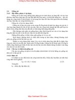
NOTE 1—If a number of thermocouples in depth are required, drill holes at varying locations on the circumference.
NOTE 2—Eliminate air pockets in junction plane by filling hole with same or similar compound as that used to make test specimen.
NOTE 3—This is a schematic representation and is not intended to be an engineering drawing.
FIG. 1 Summary of Recommended Practices for Mounting Thermocouples—Schematic Representation for “One-Piece” Cylindrical
Specimen
smaller. It is recommended also that the difference in thermal
conductivity between thermocouple assembly and the surrounding material be minimized by: (1) avoiding the use of
relatively conductive (thermal) insulation (such as ceramic and
fiberglass types) around the portion of wire that is located in
the isothermal surface that includes the thermocouple junction,
and (2) maintaining good thermal contact with the lowconductivity material by bonding the thermocouple to the
specimen (thus eliminating air pockets) with the same or
similar compound (such as an epoxy plastic) as that used to
make the specimen.
4.3 Thermocouple Wire in Isothermal Surface of Hot Junction:
4.3.1 General—Because many materials have low thermal
conductivity compared with those of thermocouple assemblies,
it has been found that certain methods of installing sensors can
produce significant errors in internal temperature measurement
(1-4).3 Errors of several hundred degrees are possible unless
heat conduction away from the sensor hot junction, by the
sensor materials, is minimized. Test results show that a
thermocouple having a sufficient length of bare wire in the
isothermal surface that includes the junction will minimize
these errors.
4.3.2 Recommendations—It is therefore recommended that
the configuration of the thermocouple sensor be such that the
leads perpendicular to the heat flow have a length equivalent to
at least 25 wire diameters on both sides of the junction in the
same isothermal surface that includes the hot junction.
5. Electrical Shorting by Conductive Char Layers
5.1 General—The char layer formed by most organic materials becomes highly conductive (electrically) as pyrolysis
progresses. Care should be taken to avoid the possibility of
electrical shorting of thermocouple lead wires not protected by
proper insulation methods. Studies (1) have shown that shorting can result in temperature errors of as much as 110 C (200
F) in thermocouples which do not employ proper insulation of
the lead wires.
4.4 Disturbances in Vicinity of Thermocouple Sensor Hot
Junctions (7-10):
4.4.1 General—It is important that a minimum amount of
disturbance be created in the material around the thermocouple
junction.
4.4.2 Recommendations—The disturbed material removal
area (for placement of the thermocouple junction and lead
wires) should be as small as possible. A maximum of No. 36
AWG gage (0.127-mm or 0.005-in.) wire should be used for
the thermocouple wire from the junction and along the isothermal surface which includes the junction. Holes drilled for
placement of thermocouple wires should be 3 wire diameters or
5.2 Recommendations—It is recommended that electrical
shorting be avoided by using a ceramic coating or tubing
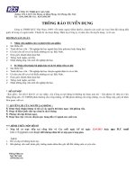
around the thermocouple lead wires. Two possible configurations are shown in Fig. 1 and Fig. 2. Use of either configuration
should provide accurate measurements in low-temperature
gradient fields (8). In that the wire temperature at the exit of the
ceramic cover in Fig. 2 may be substantially different from that
in the vicinity of the hot junction (8), the configuration in Fig.
1 should be used in high-temperature gradient fields. Care must
be taken to select an insulation that does not become electrically conductive at the temperatures being measured.
3
The boldface numbers in parentheses refer to the list of references at the end of
this practice.
2
E377 − 08 (2015)
NOTE 1—Plug and test specimen of same material.
NOTE 2—Plug, thermocouple, and junction bonded to test material with same or similar compound used to make test specimen.
NOTE 3—This is a schematic representation and is not intended to be an engineering drawing.
FIG. 2 Summary of Recommended Practices for Mounting Thermocouples—Schematic Representation for Plug-Type Cylindrical Specimen
7.2 Thermocouple Lead Wire in Isothermal Surface that
Includes the Junction—Use a length of wire at least 25 wire
diameters on both sides of the junction.
6. Thermocouple Sensor Hot Junction Location Accuracy
(4,5)
6.1 General—The thermocouple junction needs to be accurately located to assure reproducibility of data from specimen
to specimen and for accurate use of temperature data in
computer programs for determining material thickness
requirements, etc.
7.3 Thermocouple Wire Diameter and Holes for Wires—Use
a maximum of No. 36 AWG gage wire and holes as small as
possible but no larger than 3 wire diameters.
7.4 Thermal Conductance of Thermocouple Assembly—
Avoid the use of relatively conductive insulation around wire
in the isothermal surface that includes the junction. Bond
thermocouple to the material with same or similar compound.
6.2 Recommendations—The actual location of each thermocouple should be verified by X ray prior to temperature
measurement experiments. Care should be taken to correct
X-ray measurements for parallax. Thermocouple junction,
lead-wire location, and gas pockets are best checked by two X
rays taken in front and side view.
7.5 Electric Shorting by Char—Use a ceramic coating or
tubing around the thermocouple lead wires.
7. Summary of Recommendations (also summarized in
Fig. 1 and Fig. 2)
7.6 Thermocouple Sensor Hot Junction Location
Accuracy—Locate by X rays taken in front and side view.
7.1 Thermocouple Junction Bead Diameter—Make beads
no larger than 1.5 wire diameters for butt-welded junctions and
2 wire diameters for other types of welds.
8. Keywords
8.1 internal temperature; low-conductivity; thermocouple
REFERENCES
(1) ASTM MNL 12, Manual on the Use of Thermocouples in Temperature
Measurement, April 1993 (28-012093-40)
(2) ASTM STP 492, The Theory and Properties of Thermocouple
Elements, 1971 (04-492000-40)
(3) Kinzie, P.A., Thermocouple Temperature Measurement, John Wiley &
Sons, New York, N.Y., 1973.
(4) Dow, M. B., “Comparison of Measurements of Internal Temperatures
in Ablation Materials by Various Thermocouple Configurations.”
NASA Technical Note D-2165, November, 1964.
(5) Moen, W. K., “Significance of Errors in High Temperature
Measurement,” Society of Automotive Engineers, Inc., Paper No.
750F, presented at National Aeronautic and Space Engineering and
Manufacturing Meeting, Los Angeles, Calif., Sept. 23 to 27, 1963.
(6) Jakob, M., Heat Transfer, Vol II, John Wiley & Sons, Inc., New York,
1957.
(7) Moffat, R. J., “The Gradient Approach to Thermocouple
Thermometry,” Experimental Techniques, Wiley InterScience, Jan.
2008,Vol 8, Issue 4, pp. 23-25.
(8) Beck, J. V., “Thermocouple Temperature Disturbances in Low Conductivity Materials,” Transactions, TASMA, ASME, Journal of Heat
Transfer, Series C, Vol 84, 1962 , pp. 124–132.
(9) Beck, J., V., “Study of Thermal Discontinuities and Associated
Temperature Disturbances in a Solid Subject to a Surface Heat Flux,”
Part III—Effect of Sensors in Low Conductivity Material Upon
Temperature Distribution and Its Measurement, Technical Report
RAD-TR-9(7)-59-26. Contract Nos. AF 04(647)-305 and AF 04(647)258.
(10) Pfahl, R. C., Jr., Dropkin, D., “Thermocouple Temperature Perturbations in Low-Conductivity Materials,” ASME, 66-WA/HT-8,
1967.
3
E377 − 08 (2015)
ASTM International takes no position respecting the validity of any patent rights asserted in connection with any item mentioned
in this standard. Users of this standard are expressly advised that determination of the validity of any such patent rights, and the risk
of infringement of such rights, are entirely their own responsibility.
This standard is subject to revision at any time by the responsible technical committee and must be reviewed every five years and
if not revised, either reapproved or withdrawn. Your comments are invited either for revision of this standard or for additional standards
and should be addressed to ASTM International Headquarters. Your comments will receive careful consideration at a meeting of the
responsible technical committee, which you may attend. If you feel that your comments have not received a fair hearing you should
make your views known to the ASTM Committee on Standards, at the address shown below.
This standard is copyrighted by ASTM International, 100 Barr Harbor Drive, PO Box C700, West Conshohocken, PA 19428-2959,
United States. Individual reprints (single or multiple copies) of this standard may be obtained by contacting ASTM at the above
address or at 610-832-9585 (phone), 610-832-9555 (fax), or (e-mail); or through the ASTM website
(www.astm.org). Permission rights to photocopy the standard may also be secured from the Copyright Clearance Center, 222
Rosewood Drive, Danvers, MA 01923, Tel: (978) 646-2600; />
4