Controller area network dowload
Bạn đang xem bản rút gọn của tài liệu. Xem và tải ngay bản đầy đủ của tài liệu tại đây (286.89 KB, 9 trang )
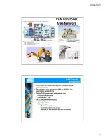
Controller Area Network (CAN)
Diagnostics
Copyright AA1Car
Controller Area Network (CAN) electrical systems began to appear in new
vehicles in 2003. Since then, more and more vehicles have been equipped with
CAN systems, until 2008 when virtually all passenger cars and light trucks sold in
the U.S. were CAN-equipped.
As a vehicle owner or do-it-yourself mechanic, you need to know how CAN has
made the electrical system in late model cars and trucks much more complicated
than ever before. CAN allows various modules and systems to share data and
interact in ways that where previously impossible.
So what exactly is CAN? It is a communication standard that allows the various
modules and computers in a vehicle to talk to one another via a common "data
bus" circuit in the wiring system. Think of it as a high speed party line that allows
data and commands to zip back and forth from one module to another. This
allows the Powertrain Control Module (PCM), antilock brake/traction
control/stability control system, electronic steering, electronic suspension,
automatic climate control system, keyless entry system, lighting control modules
and dozens of other systems and modules to all be interconnected electronically.
The Development of Controller Area Networks for Cars
CAN was created in 1984 by the Robert Bosch Corp. in anticipation of future
advances in onboard electronics. The first production application was in 1992 on
several Mercedes-Benz models. Today you will find it on all new vehicles.
CAN Diagnostics
If you don't know the difference between a CAN data bus and a school bus,
you're not alone. Even many professional mechanics are not yet up to speed on
CAN diagnostics. Troubleshooting a late model CAN car is really no different
than troubleshooting any late model OBD II vehicles. You need a scan tool to
read out fault codes and other sensor data, and you need a scan tool that is CAN
compliant. That means it has the proper software and hardware to communicate
with the vehicle at higher speeds.
Older scan tools (namely, most of those made before about 2006) lack the
circuitry to talk to a CAN system. Some older scan tools have the right hardware,
and can be upgraded with new software. But in most cases you will need a
newer scan tool that is CAN-compliant to do onboard diagnostics.
Most inexpensive scan tools designed for the DIY market are on-e-way tools:
they can read codes and data, but they cannot send commands to the vehicle
that are necessary to run all kinds of system self-tests. That degree of
sophistication is reserved for more expensive professional level scan tools or
factory scan tools. In addition, the software in a typical DIY scan tool (even if it is
CAN-compliant) can usually only access powertrain codes. It can't talk to the
ABS system, climate control system, electronic steering or suspension systems,
climate control system, airbag system or other onboard electronics. In other
words, it is a very limited tool. For advanced diagnositics that go beyond sijply
reading powertrain fault codes and sensor data, you need a professional level
tool or a factory tool. The latter can be quite expensive, costing thousands of
dollars plus annual software updates that can add hundreds more. So if you
need advanced diagnostics, the only option for most motorists and DIYers is to
take your vehicle to a repair shop that has the proper diagnostic equipment.
How Information Moves Around in a CAN System
Like many current vehicles, information in a CAN-equipped vehicle is shared
over a serial data bus. The bus is the circuit that carries all the electronic chatter
between modules (nodes). The bus may have one wire or two. If it has two, the
wires are usually twisted to cancel out electromagnetic interference. The speed
at which the bus carries information will vary depending on the "class" rating of
the bus as well as the protocol to which it conforms.
A data bus with a "Class A" speed rating is a relatively slow, low-speed circuit
that typically carries less than 10 kilobits (10 Kbps) of information per second. A
data bus that operates at Class A speeds is limited to simple command functions
like operating power mirrors, power seats, power widows, power door locks,
remote trunk releases and lights.
A data bus with a "Class B" rating, by comparison, may operate from 10 Kbps up
to 125 Kbps, depending on the operating protocol (SAE J1850 or Europe's ISO
9141-2). This is fast enough to carry more complex information and time-
sensitive data. Systems that may may share a data bus with a Class B rating
include electronic instrumentation, electronic transmission controls, security
systems, and climate control.
Class C is currently the fastest data bus rating. Class C systems can operate at
speeds up to 1 megabits per second, which is up to 100 times faster than a
typical Class B data bus. Many of the vehicles that are currently using a Class C
data bus are operating at speeds of around 500 Kbps, which is fast enough for
powertrain control modules, air bag modules, and fast-acting antilock brake and
stability control systems. Eeven faster CAN systems are coming with "class D"
ratings of over 1 megabytes per second. And some applications such as onboard
entertainment systems require even higher speed audio and video streaming.
One thing to keep in mind about the CAN standard is that CAN as well as other
protocols such as SAE J1939, GMLAN, OBD II, SAE J1587 and LIN have more
to do with the way information is formatted, transmitted and received than how
fast it is sent. This means the automotive engineers who design the onboard
electronics for CAN-compliant vehicles are free to choose any operating speed
they want (up to one megabits per second) as well as the type of bus conductor
(one wire, twisted paired wires or a fiber optic cable). On most cars today, a high-
speed data bus is needed to handle the volume of information going back and
forth between all the onboard electronics.
In 1995, GM introduced its own "Class 2" data bus to handle communication
between modules. The system ran at a speed of 10,400 bits per second (10.4
Kbps), which was more than adequate for vehicles a decade ago. In 2004, GM
moved to their next generation data bus system which they called "GMLAN" (GM
Local Area Network). Introduced on the Cadillac XLR and Saturn Ion, GMLAN
added the capability to operate at two speeds on two separate buses: a low
speed (33.33 Kbps) bus and a high speed (500 Kbps) bus.
The low speed side of the GMLAN system operates on a single wire bus to
handle body-related control functions, while the high speed bus uses two wires to
carry data between the powertrain, transmission and antilock brake modules. A
"gateway" node connects the high speed bus and low speed bus, and allows
information to be shared back and forth. For example, the radio (which is
connected to the low speed bus) may adjust volume based on engine speed and
vehicle speed (from the high speed bus) to offset road noise.
Mercedes also uses several different bus speeds on their vehicles. Depending on
the application, there may be a high-speed 500 Kbps CAN-C bus for the
powertrain, transmission and ABS modules, and a slower-speed 83 Kbps CAN-B
bus for the body control functions. On some Mercedes cars, there may be as
many as 30 modules on the CAN-B bus. Up to model year 2002, all
communication between the CAN-C and CAN-B bus went through the electronic
ignition switch (EIS) module. After 2002, a new "gateway" module handles
the inter-bus communications as well as onboard diagnostics via a CAN-D bus.
.
How CAN Data is Sent and Received
If your eyes haven't glazed over yet, here's how data is sent and received in a
CAN system. Every module (node) that is attached to the data bus network is
capable of sending and receiving signals. Each module (node) has its own
unique address on the network. This allows the module to receive the inputs and
data it needs to function, while ignoring information intended for other modules
that share the network. When a module transmits information over the network,
the information is coded so all the other modules recognize where it came from.
Data is sent as a series of digital bits consisting of "0's" and "1's". If you looked at
the data on a scope, you would see a square wave pattern that changes between
a high and low voltage reading. The low voltage reading usually corresponds to
the "0" while the high voltage reading corresponds to the "1". The actual voltage
readings will vary depending on the application and protocols the vehicle
manufacturer is using, but most operate in the 5 to 7 volts range.
The CAN standard requires a "base frame" format for the data. What this means
is that for each distinct message sent or received by a module on the network,
there is a beginning bit (called the "start of frame" or "start of message" bit),
followed by an "identifier" code (an 11 bit code that tells what kind of data the
message contains), followed by a priority code ("remote transmission request")
that says how important the data is, followed by 0 to 8 bytes (one byte equals 8
bits) of actual data, followed by some more bits that verify the information (cyclic
redundancy check), followed by some end of message bits and an "end-of-
frame" bit.
Still with me? There's more! One of the tasks of any network system is to keep all
the messages separated so they don't collide and garble one another. Usually
the body control module or instrument cluster module is assigned the task of
managing the network traffic. When it sees a message coming over the bus, it
looks at the first bit in the data stream. If the bit is a "0", the message is given
priority over the others. This is called a "dominant" message. If the first bit is a "1"
it is given a lower priority (a "recessive" message). Thus, the highest priority
messages always get through to their intended destinations but the low priority
messages may be temporarily blocked until the traffic eases up.
CAN Faults
CAN-compliant vehicles are just as vulnerable to electronic faults as older
vehicles. Though CAN systems use fewer wires and fewer connectors to save
weight and cost, they also use more modules and more complicated modules.
Communication problems can occur if module connectors become corroded or
loose, if wires become grounded, shorted or break, or system voltage is below
specifications. Some modules may even forget their settings or locations if the
battery is disconnected or goes dead.
On some Chrysler minivans, for example, the automatic climate control system
will quit working if battery power is lost. This happens because the electric
stepper motors that control the position of the blend doors forget their locations.
The system has to be put into a "relearn" mode to re-establish all the motor
locations and settings.
Various kinds of problems can occur on other CAN-equipped vehicles when the
battery is disconnected or goes dead. The modules in the CAN system require a
certain amount of voltage for their Keep Alive Memory settings. If this is lost, the
module will forget these settings and may not function properly until it has time to
relearn the lost data. In some cases, this requires a special relearn procedure
using a scan tool because the module can't do the relearn by itself. And on some
vehicles, the module may go to sleep and not wake up until it is pinged by a scan
tool or the main gateway module (usually the body control module). Relearning
procedures typically require a factory scan tool or a professional level aftermarket
scan tool.
One of the features of CAN and other network systems is that modules can send
and receive "ok" signals to let the main control module know if they are working
or not. In theory, this makes diagnostics easier. On the other hand, it also means
that one misbehaving module may generate enough noise to disrupt the entire
network causing a complete shutdown of the vehicle!
When a serial bus communication problem occurs, it will usually set a "U"
diagnostic trouble code (DTC) and turn on the Malfunction Indicator Lamp (MIL).
Depending on the fault, the vehicle may or may not start, or it may only operate
in a "limp-in" mode with limited capabilities. Loss of communication between the
engine controller and transmission controller (code U1026 on a GM, for example)
may put the transmission into a limp-in mode where it will only operate in one or
two gears.
Loss of communication codes may indicate a wiring problem on the bus, or a
fault with a module. Isolating the fault may require unplugging modules one at a
time until the fault is found. Just remember that all modules on a bus network
need three things to function properly: power, ground and a serial data
connection.
When diagnosing bus or module communication problems, you usually start by
checking for voltage at the module, then the ground connection, and finally the
data line. If all three are good but the module isn't working, the module needs to
be replaced.
On GM applications, a code U100 or U1255 means a general loss of
communication on the data bus. With a Tech 2 scan tool, you can go to
Diagnostic Circuit Check, then Message Monitor to see a list of active modules
and compare it to the list of modules that are supposed to be on when the key is
on.
To minimize the parasitic current drain on the battery when the vehicle is off, a
"sleep" signal is sent to the modules on the network. Some may remain on for a
short period of time after the ignition is switched off (air bag module, for
example), and some may never go to sleep (anti-theft module and keyless entry
receiver, for example) but most are put into a sleep mode to save battery power.
If the sleep signal is never sent, or a module fails to recognize the sleep signal, it
may remain active and pull power from the battery. Depending on the current
draw, this may run down the battery if the vehicle sits for a period of time.
Late Model Vehicles with Controller Area Network Systems:
2003 Ford Excursion, 2003 Ford F-250 & F-350, 2003 Ford Focus &
Thunderbird, 2003 General Motors Saturn ION, 2003 Lincoln LS, 2003 Mazda 6,
and 2003 SAAB 9-3
2004 Buick Rendezvous, 2004 Cadillac CTS, XLR & SRX, 2004 Dodge Durango,
2004 Ford Explorer, 2004 Ford F-150, E-250 & E-350, 2004 Ford Taurus, 2004
Lexus LS430, 2004 Mercury Mountaineer, 2004 Mercury Sable, 2004 Mazda 3 &
RX-8, 2004 Toyota Prius, and 2004 Volvo S40
2005 Audi A4 & A6, 2005 Buick LaCrosse, Rendevous & Ranier, 2005 Cadillac
STS, 2005 Chevrolet Cobalt, Corvette & Malibu, 2005 Chevrolet Equinox, 2005
Chevrolet SSR, 2005 Chevrolet Trailblazer EXT, 2005 Chrysler 300C, 2005
Dodge Dakota & Magnum, 2005 Ford Crown Victoria, Five Hundred, Focus &
Mustang, 2005 Ford E-150, 2005 Ford Escape & Expedition, 2005 Ford
Freestyle, 2005 GMC Envoy ESV & XL, 2005 Isuzu Ascender, 2005 Jeep Grand
Cherokee, 2005 Lexus LS400 & GX470, 2005 Lincoln Town Car, 2005 Mercury
Grand Marquis, Montigo & Sable, 2005 Mercury Mariner, 2005 Pontiac G6,
Grand Prix & GTO, 2005 Land Rover LR3, 2005 Mazda MPV & Tribute, 2005
Mercedes SLK350, 2005 SAAB 9-7X, 2005 Toyota Avalon, 2005 Toyota
4Runner, Sequoia, Tacoma & Tundra, and 2005 Volvo S60, S80, V50, V70,
XC90
Essentially ALL 2008 and newer model year passenger cars and light trucks.