Tiêu chuẩn iso 13586 2000 + amd1 2003 scan
Bạn đang xem bản rút gọn của tài liệu. Xem và tải ngay bản đầy đủ của tài liệu tại đây (745.99 KB, 33 trang )
IS0
INTERNATIONAL
STANDARD
First edition
2000-03-01
AMENDMENT 1
2003-06-01
Plastics - Determination of fracture
toughness (GIG and KIC)- Linear elastic
fracture mechanics (LEFM) approach
AMENDMENT 1: Guidelines for the testing
of injection-moulded plastics containing
discont inuous reinforcing fib res
Plastiques - Détermination de la ténacité à la rupture (Gic et Kid Application de la mécanique linéaire élastique de la rupture (LEFM)
--`,,`,-`-`,,`,,`,`,,`---
AMENDEMENT 1: Lignes directrices relatives à l'essai des matériaux
plastiques moulés par injection contenant des fibres de renfort
discontinues
Reference number
IS0 13586:2000/Amd.l:2003(E)
Copyright International Organization for Standardization
Provided by IHS under license with ISO
No reproduction or networking permitted without license from IHS
@
Not for Resale
IS0 2003
IS0 13586:2000/Amd.l:2003(E)
PDF disclaimer
This PDF file may contain embedded typefaces. In accordance with Adobe's licensing policy, this file may be printed or viewed but
shall not be edited unless the typefaces which are embedded are licensed to and installed on the computer performing the editing. In
downloading this file, parties accept therein the responsibility of not infringing Adobe's licensing policy. The IS0 Central Secretariat
accepts no liability in this area.
Adobe is a trademark of Adobe Systems Incorporated.
Details of the sofiware products used to create this PDF file can be found in the General Info relative to the file; the PDF-creation
parameters were optimized for printing. Every care has been taken to ensure that the file is suitable for use by IS0 member bodies. In
the unlikely event that a problem relating to it is found, please inform the Central Secretariat at the address given below.
--`,,`,-`-`,,`,,`,`,,`---
O IS02003
All rights reserved. Unless otherwise specified, no part of this publication may be reproduced or utilized in any form or by any means,
electronic or mechanical, including photocopying and microfilm, without permission in writing from either IS0 at the address below or
ISOs member body in the country of the requester.
IS0 copyright office
Case postale 56 CH-I211 Geneva 20
Tel. + 41 22 749 O1 11
Fax + 4 1 227490947
Web www.iso.org
Published in Switzerland
ii
Copyright International Organization for Standardization
Provided by IHS under license with ISO
No reproduction or networking permitted without license from IHS
O IS0 2003 -All
Not for Resale
rights reserved
IS0 13586:2000/Amd.l:2003(E)
Foreword
IS0 (the International Organization for Standardization) is a worldwide federation of national standards bodies
(IS0 member bodies). The work of preparing International Standards is normally carried out through IS0
technical committees. Each member body interested in a subject for which a technical committee has been
established has the right to be represented on that committee. International organizations, governmental and
non-governmental, in liaison with ISO, also take part in the work. IS0 collaborates closely with the
International Electrotechnical Commission (I EC) on all matters of electrotechnical standardization.
International Standards are drafted in accordance with the rules given in the ISO/IEC Directives, Part 2.
The main task of technical committees is to prepare International Standards. Draft International Standards
adopted by the technical committees are circulated to the member bodies for voting. Publication as an
International Standard requires approval by at least 75 % of the member bodies casting a vote.
Attention is drawn to the possibility that some of the elements of this document may be the subject of patent
rights. IS0 shall not be held responsible for identifying any or all such patent rights.
Amendment 1 to IS0 13586:2000 was prepared by Technical Committee ISOíTC 61, Plastics, Subcommittee
SC 2, Mechanical properties. It is based on guidelines originally developed by Technical Committee TC 4 of
the European Structural Integrity Society (ESIS).
--`,,`,-`-`,,`,,`,`,,`---
O IS0 2003 -All
iii
rights reserved
Copyright International Organization for Standardization
Provided by IHS under license with ISO
No reproduction or networking permitted without license from IHS
Not for Resale
--`,,`,-`-`,,`,,`,`,,`---
Copyright International Organization for Standardization
Provided by IHS under license with ISO
No reproduction or networking permitted without license from IHS
Not for Resale
IS0 13586:2000/Amd.l:2003(E)
Plastics - Determination of fracture toughness (GIG and KIC)Linear elastic fracture mechanics (LEFM) approach
AMENDMENT 1: Guidelines for the testing of injection-moulded
plastics conta¡ning discontinuous reinforcing fibres
Page 1
Update Clause 2 (normative references) as follows:
Replace IS0 604: 1993 by IS0 604:2002 (same title).
Replace IS0 5893: 1993 by IS0 5893:2002, Rubber and plastics test equipment - Tensile, flexural and
compression fypes (constant rate of traverse) - Specification.
Page 16
Add the following references to the Bibliography:
FOLKES,M. Short fibre reinforced thermoplastics, Research Studies Press, J. Wiley (1992)
LOWE,A.C., MOORE,D.R., RUTER, P.M. impact and dynamic fracture of polymers and composites,
ESIS Publication 19, edited by J.G. Williams and A. Pavan, p. 383, MEP Ltd (London) (1995)
MOORE,D.R., Experimental Methods in the Application of Fracture Mechanics Principles to the Testing
of Polymers and Composites, Chapter 1, p. 59, The Measurement of Kc and Ge at Slow Speeds for
Discontinuous Fibre Composites,edited by B.R.K. Blackman, D.R. Moore, A. Pavan and J.G. Williams,
ISBN 008 043689 7, Elsevier Science (2001)
DAVIS,M., MOORE,D.R. Composites Science & Technology,40, p. 131 (1991)
Page 16
Add the following annex before the Bibliography.
--`,,`,-`-`,,`,,`,`,,`---
O IS0 2003 -All
rights reserved
Copyright International Organization for Standardization
Provided by IHS under license with ISO
No reproduction or networking permitted without license from IHS
Not for Resale
1
IS0 13586:2000/Amd.l:2003(E)
Annex B
(informative)
Guidelines for the testing of injection-moulded plastics containing
discont inuous reinforci ng fibres
B.l General
IS0 13586 was developed for non-reinforced plastics. However, with the proliferation of injection-moulded
products made from fibre-reinforced plastics, it was considered appropriate that some guidelines be given to
users who want to apply this International Standard to measure the toughness of reinforced composite
materials. Whilst the theoretical basis which underpins the standard cannot be rigorously applied to reinforced
plastics, informative results can be obtained.
--`,,`,-`-`,,`,,`,`,,`---
When applying this International Standard to injection-moulded plastics containing discontinuous reinforcing
fibres, three issues arise. The first of these relates to sample morphology stemming from the injectionmoulding manufacturing method. The second relates to a feature involved in crack initiation and the third
concerns the application of LEFM to this class of anisotropic, heterogeneous material and the validity of the
toughness values.
B.2 Effect of injection moulding on fibre alignment
During the injection moulding of plastics containing discontinuous reinforcing fibres, the melt is delivered into a
mould tool under a shear stress field. This causes the fibres to be aligned in the direction of mould fill.
However, the melt strikes a cold mould surface and quickly solidifies. Therefore, the fibres aligned in the
direction of mould fill are generally near to the mould surface. The melt that enters the central or core region of
the mould is then subjected to a stress field where the deformations are extensional, ¡.e. a diverging stress
field 181. This aligns the fibres in this core region at approximately right angles to the direction of mould fill. In
simplistic terms, a skin-core-skin structure is established through the thickness of the moulding. Of course, in
reality this is an over-simplification of a much more complex fibre orientation, but an adequate approximation
for an assessment of toughness. The mould thickness will then determine which layer will be dominant, with
thin mouldings being skin-dominated and thicker mouldings being core-dominated.
B.3 Guidelines for the preparation of samples
These guidelines require that the direction of mould fill from the injection-moulding process be known for the
material to be tested. An injection moulding will have in-plane anisotropy and through-thickness heterogeneity.
The moulding will have three mutually perpendicular directions, as follows:
L
Longitudinal, ¡.e. in the processing direction;
T
Transverse, ¡.e. in the mould width direction;
S Short transverse, ¡.e. in the through-thickness direction.
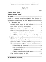
The anisotropic sheet shown in Figure B.l will have six different directions of toughness for which six
specimens designated T-S, L-S, S-T, T-L, L-T and S-L can be used for measurement purposes. The first letter
designates the direction normal to the crack plane, ¡.e. the direction of the stress applied to generate a
colinear crack. The second letter is the expected direction of crack propagation. However, in practice the
specimens have to be cut with a thickness equal to the thickness of the moulding, so only the T-L and L-T
specimens can be used and it is recommended that both T-L and L-T specimens be prepared. Thus both the
2
Copyright International Organization for Standardization
Provided by IHS under license with ISO
No reproduction or networking permitted without license from IHS
O IS0 2003 -All
Not for Resale
rights reserved
IS0 13586:2000/Amd.1:2003(E)
--`,,`,-`-`,,`,,`,`,,`---
T-L and L-T specimens will have a thickness h equal to the mould thickness. Either SENB or CT specimens
may be used. Specimens should not be cut from close to the edge of the moulding. The notch tip radius
should be sharp and it is recommended that it should be less than 50 pm.
Key
L longitudinal direction (direction of mould fill)
T
S
o
long transverse direction (mould width direction)
short transverse direction (through-thickness direction)
direction of stress
Figure B.l
O IS0 2003 -All
- Specimen configuration for an anisotropic sheet (illustrated for a CT specimen)
3
rights reserved
Copyright International Organization for Standardization
Provided by IHS under license with ISO
No reproduction or networking permitted without license from IHS
Not for Resale
IS0 13586:2000/Amd.l:2003(E)
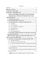
B.4 Guidelines for the interpretation of the load-displacement curve when “pop-in”
occurs
When testing injection-moulded plastics containing discontinuous reinforcing fibres, a force decrease (termed
“pop-in”) is sometimes observed 191 on the load-displacement curve prior to the main peak as shown in
Figure B.2. This initial peak force is followed by a drop which can then be followed by a further, often
significant, rise. If the stiffness, ¡.e. the slope of the force-displacement curve, reduces after the drop in the
force, then it is likely that the crack has initiated. When this is observed, the value of the force at which the
“pop-in” occurs should be taken as FQ. When “pop-in” does not occur, the trace should be interpreted as
described in Clause 6 and shown in Figure 7.
1
Displacement, s
Key
1 “pop-in’’
Figure B.2 - Load-displacement curve for a notched test specimen made from injection-moulded
plastic containing discontinuous reinforcing fibres when “pop-in” occurs
B.5 Guidelines for assessing the colinearity of the crack growth
The crack growth in homogeneous polymeric materials should be colinear and grow in the direction at right
angles to the direction of the applied stress. However, for a discontinuous-fibre-reinforced composite the crack
growth will usually not be colinear. It is informative to assess the extent of non-colinearity of each specimen
after the test. It is recommended that this be done by firstly observing the fractured surface side-on to the
crack growth and then by examination of the plane of the crack. A visual observation of the side-on view will
provide information on the degree of colinearity at the edge of the specimen, ¡.e. in the “skin” layer. Then, by
microscopic examination of the plane of the crack, an estimation can be made of the skin thickness ts and of
the core thickness tc. These regions can be identified due to the preferential alignment of the fibres during
injection moulding as described in Clause B.2. When the crack grows through a region of the moulding where
--`,,`,-`-`,,`,,`,`,,`---
4
Copyright International Organization for Standardization
Provided by IHS under license with ISO
No reproduction or networking permitted without license from IHS
O IS0 2003 -All
Not for Resale
rights reserved
IS0 13586:2000/Amd.l:2003(E)
the fibres are aligned parallel to the crack, a smooth fracture surface is observed. However, when the crack
grows through a region of the moulding where the fibres are aligned perpendicular to the crack, then a rough
fracture surface is observed. It follows therefore that the fracture surface of the L-T specimen will have a
smooth core layer and rough skin layers. However, the fracture surface of the T-L specimens will have a
rough core layer and smooth skin layers.
B.6 Estimation of the smooth fraction for L-T and T-L specimens
If the thickness of the skin layer ts and the thickness of the core layer tc are measured optically, then the
amount of smooth fracture, termed the smooth fraction, can be estimated. In T-L specimens, the smooth
fraction is the value of 2ts/h and for the L-T specimens it is the value of tc/h, where h is the thickness of the
specimen as defined in Figure 1 for the SENB specimen and Figure 3 for the CT specimen.
--`,,`,-`-`,,`,,`,`,,`---
A smooth fraction of unity implies a completely smooth fracture surface (as would typically be obtained when
fracturing an unreinforced polymer) and a smooth fraction of zero implies a completely rough fracture surface.
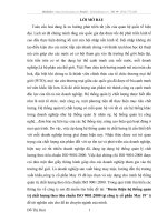
obtained by ESIS TC 4 on a 50 % by mass glass polyamide composite are shown in
Round-robin results [lo]
Figure B.3. Reference [4] discusses in detail the nature of the results, the interpretation of the fracture surface
and the shape of the curve in Figure B.3. Further discussion is beyond the scope of this test method. The
results show that, as the smooth fraction tends towards unity, then the Kc value should tend towards the
plane strain value for the resin. From these data, an anticipated resin Kc value of around 3 3 MPa-m1I2would
be suggested, which does seem reasonable. When the smooth fraction tends towards zero, the fracture
process is dominated by fibre pull-out and breaking fibres, so a large Kc would be expected, as was indeed
observed.
rn
rn
Figure B.3 -Kc plotted against the smooth fraction of the fracture surface for 50 % by mass
glass-fibre-reinforced polyarylamide injection mouldings of thickness 2 mm and 5 mm
B.7 Guidelines for comparing the toughness of two different reinforced materials
When comparing toughness values measured for different discontinuous-fibre-reinforced composites, it is
recommended that values of Kc versus smooth fraction be plotted for each composite. The values of Kc at a
common smooth fraction can then be compared. The larger Kc value will infer the higher toughness. The
O IS0 2003 -All
5
rights reserved
Copyright International Organization for Standardization
Provided by IHS under license with ISO
No reproduction or networking permitted without license from IHS
Not for Resale
IS0 13586:2000/Amd.l:2003(E)
quality of the comparison will be improved if a mid-range value for the smooth fraction is chosen for the
comparison.
B.8 Guidelines for measuring the yield strength
To apply the size criteria, a value of the tensile yield strength ouis required. However, for discontinuous-fibrereinforced composites this should not be measured in tension because tensile failure will be accompanied by
Therefore, it is
other processes such as fibre pull-out, fibre fracture, debonding and matrix cracking [I1].
recommended that a value of 0,7 times the compressive yield stress be used. This can be measured using the
standard method for compressive testing, IS0 604. During compressive testing, the stress should be aligned
in the T direction for T-L specimens and in the L direction for L-T specimens so that an appropriate value of
the compressive yield stress, and hence ou,
can be determined.
B.9 Validity of the data
The size criteria outlined in 6.4 are rigorous, and give validity criteria for the measured toughness values. It
has been shown that this rigorous approach cannot be applied to injection-moulded discontinuous-fibrereinforced composites. The size criteria can, however, be considered as quality criteria for these materials and
informative (though non-rigorous) values of Kc and G , can be obtained. In addition, when plotted against the
smooth fraction of the fracture surface, these parameters can provide a powerful means of comparing
materials.
--`,,`,-`-`,,`,,`,`,,`---
6
Copyright International Organization for Standardization
Provided by IHS under license with ISO
No reproduction or networking permitted without license from IHS
O IS0 2003 -All
Not for Resale
rights reserved
--`,,`,-`-`,,`,,`,`,,`---
Copyright International Organization for Standardization
Provided by IHS under license with ISO
No reproduction or networking permitted without license from IHS
Not for Resale
IS0 13586:2000/Amd.l:2003(E)
ICs 83.080.01
Price based on 6 pages
--`,,`,-`-`,,`,,`,`,,`---
O IS0 2003 -All
rights reserved
Copyright International Organization for Standardization
Provided by IHS under license with ISO
No reproduction or networking permitted without license from IHS
Not for Resale
STDOIS0 L358b-ENGL 2000
4853903 0822324 413
INTERNATIONAL
STANDARD
IS0
13586
First edition
2000-03-01
Plastics - Determination of fracture
toughness (Glc and KIC)- Linear elastic
fracture mechanics (LEFM) approach
Plastiques -Détermination de la tenacité à la rupture (Glc et Klc) Application de la mécanique linéaire élastique de la rupture (LEFM)
--`,,`,-`-`,,`,,`,`,,`---
This material is reproduccd froiii IS0 docunieiits under International Organizatioli f
Standardization (ISO) Copyright License Nuiiiber HIS/CC/1996. Not for resale. No
part oftliese IS0 documents iiiay be reproduced i n any fortil, electronic retrieval
system or otherwise, except as allowed in thc copyright law oftlie coiintry of use, or
with the prior written consent oflSO (Case postale 56,121 1 Geneva 20, Switzerland,
Fax +41 22 734 i 0 79), 1HS or the IS0 Licensor’s nieinbers.
Reference number
IS0 13586:2000(E)
Q IS0 2000
Copyright International Organization for Standardization
Provided by IHS under license with ISO
No reproduction or networking permitted without license from IHS
Not for Resale
4853903 0822325 35T D
STD-ISO L358b-ENGL 2000
Is0 13586:2000(E)
PDF disclaimer
This PDF file may contain embedded typefaces. In accordance with Adobe's licensing policy, this file may be printed of viewed but shall not
be edited unless the typefaces which are embedded are licensed to and installed on the computer performing the editing. In downloading this
file, parties accept therein the responsibility of not infringing Adobe's licensing policy. The IS0 Central Secretariat accepts no liability in this
area.
Adobe is a trademark of Adobe Systems Incorporated.
Details of the software products used to create this PDF file can be found in the General Info relative to the file; the PDF-creation parameters
were optimized for printing. Every care has been taken to ensure that the file is suitable for use by IS0 member bodies. In the unlikely event
that a problem relating to it is found, please inform the Central Secretariat at the address given below.
Q Is02000
All rights reserved. Unless otherwise specified, no part of this publication may be reproduced or utilized in any form or by any means, electronic
or mechanical, including photocopying and microfilm, without permission in writing from either I S 0 at the address below or ISOs member body
in the country of the requester.
I S 0 copyright office
Case postale 56 CH-1211 Geneva 20
Tel. + 41 22 749 O1 11
Fax + 4 1 2 2 7 3 4 1 0 7 9
E-mail copyrightOiso.ch
Web www.iso.ch
Printed in Switzerland
63 IS0 2000 -All rights reserved
--`,,`,-`-`,,`,,`,`,,`---
Copyright International Organization for Standardization
Provided by IHS under license with ISO
No reproduction or networking permitted without license from IHS
Not for Resale
~
STD=ISO 3358b-ENGL 2000
= 4853903 0822326 296IS0I
13586:2000(E)
Contents
2
.....................................................................................................................................................................
Scope ..............................................................................................................................................................
Normative references ....................................................................................................................................
3
Terms and definitions
4
Test specimens ..............................................................................................................................................
5
Testing
Foreword
1
...................................................................................................................................
iv
1
1
2
4
6
............................................................................................................................................................
Expression of results ....................................................................................................................................
7
Precision
9
8
Test report ......................................................................................................................................................
9
.........................................................................................................................................................
................................................................................................................
Bibliography..............................................................................................................................................................
Annex A (normative) Calibration factors
5
6
14
16
--`,,`,-`-`,,`,,`,`,,`---
iii
Q I S 0 2000 -All rights reserved
Copyright International Organization for Standardization
Provided by IHS under license with ISO
No reproduction or networking permitted without license from IHS
Not for Resale
STD-IS0 Ii35Bb-ENGL 2000
4853903 0822327 1 2 2
IS0 13586:2000(E)
Foreword
IS0 (the International Organization for Standardization) is a worldwide federation of national standards bodies (IS0
member bodies). The work of preparing International Standards is normally carried out through IS0 technical
committees. Each member body interested in a subject for which a technical committee has been established has
the right to be represented on that committee. International organizations, governmental and non-governmental, in
liaison with ISO, also take part in the work. IS0 collaborates closely with the International Electrotechnical
Commission (IEC) on all matters of electrotechnical standardization.
International Standards are drafted in accordance with the rules given in the ISO/IEC Directives, Part 3.
Draft International Standards adopted by the technical committees are circulated to the member bodies for voting.
Publication as an International Standard requires approval by at least 75 % of the member bodies casting a vote.
Attention is drawn to the possibility that some of the elements of this International Standard may be the subject of
patent rights. I S 0 shall not be held responsible for identifying any or all such patent rights.
International Standard IS0 13586 was prepared by Technical Committee ISO/TC 61, Plastics, Subcommittee SC 2,
Mechanical properties.
--`,,`,-`-`,,`,,`,`,,`---
Annex A forms a normative part of this of IS0 13586.
O I S 0 2000 - All rights reserved
iv
Copyright International Organization for Standardization
Provided by IHS under license with ISO
No reproduction or networking permitted without license from IHS
Not for Resale
STD-IS0 3358b-ENGL 2000
I4853903 0822328 Ob9
INTERNATIONAL STANDARD
IS0 13586:2000(E)
Plastics - Determination of fracture toughness (GIC et KIC)Linear elastic fracture mechanics (LEFM) approach
--`,,`,-`-`,,`,,`,`,,`---
1
Scope
This International Standard specifies the principles for determining the fracture toughness of plastics in the crackopening mode (mode I) under defined conditions. Two test methods with cracked specimens are defined, namely
three-point-bending tests and compact-specimen tensile tests in order to suit different types of equipment available
or different types of material.
The methods are suitable for use with the following range of materials:
- rigid and semi-rigid thermoplastic moulding, extrusion and casting materials;
- rigid and semi-rigid thermosetting moulding and casting materials.
Certain restrictions on the linearity of the load-displacement diagram, on the specimen width and on the thickness
are imposed to ensure validity (see 6.4) since the scheme used assumes linear elastic behaviour of the cracked
material and a state of plane strain at the crack tip. Finally, the crack must be sharp enough so that an even
sharper crack will not result in significantly lower values of the measured properties.
l
2
Normative references
The following normative documents contain provisions which, through reference in this text, constitute provisions of
this International Standard. For dated references, subsequent amendments to, or revisions of, any of these
publications do not apply. However, parties to agreements based on this International Standard are encouraged to
investigate the possibility of applying the most recent editions of the normative documents indicated below. For
undated references, the latest edition of the normative document referred to applies. Members of IS0 and IEC
maintain registers of currently valid International Standards.
IS0 291:1997, Plastics - Standard atmospheres for conditioning and testing.
IS0 527-1:1993, Plastics - Determination of tensile properties - Part 7: General principles.
IS0 604: 1993, Plastics - Determination of compressiveproperties.
IS0 2818:1994, Plastics - Preparation of test specimens by machining.
IS0 5893:1993, Rubber and plastics test equipment - Tensile, flexural and compression types (constant rate of
traverse) -Description.
4
1
Q IS0 2 0 0 - All rights received
Copyright International Organization for Standardization
Provided by IHS under license with ISO
No reproduction or networking permitted without license from IHS
Not for Resale
STDmISO 13586-ENGL 2000
4853903 0822329 .TT5
=
I S 0 13586:2000(E)
3
Terms and definitions
For the purposes of this International Standard, the following terms and definitions apply:
3.1
energy release rate
--`,,`,-`-`,,`,,`,`,,`---
G
the change in the external work SUe, and strain energy SU, of a deformed body due to enlargement of the cracked
area 6A
It is expressed in joules per square metre, Jim2.
3.2
critical energy release rate
GIC
the value of the energy release rate G in a precracked specimen under plane-strain loading conditions, when the
crack starts to grow
It is expressed in joules per square metre, J/m2.
3.3
stress intensity factor
K
the limiting value of the product of the stress o(r) perpendicular to the crack area at a distance r from the crack tip
and of the square root of 2nr, for small values of r
It is expressed in Pa.dm.
The term factor is used here because it is common usage, even though the value has dimensions.
3.4
critical stress intensity factor
KIC
the value of the stress intensity factor when the crack under load actually starts to enlarge under a plane-strain
loading condition around the crack tip
It is expressed in Pa.dm.
The critical stress intensity factor Klc of a material is related to its critical energy release rate GI, by the equation
where E is the modulus of elasticity, determined under similar conditions of loading time (up to crack initiation) and
temperature.
In the case of plane-strain conditions:
E = - Et
(4)
1-p2
-
2
Copyright International Organization for Standardization
Provided by IHS under license with ISO
No reproduction or networking permitted without license from IHS
Q I S 0 2000 All rights reserved
Not for Resale
~
STD-IS0 3358b-ENGL 2000
4 8 5 3 9 0 3 0 8 2 2 3 3 0 717
m
I S 0 13586:2000(E)
Et
p
--`,,`,-`-`,,`,,`,`,,`---
where
is the tensile modulus (see I S 0 527-1);
is Poisson’s ratio (see IS0 527-1-).
3.5
displacement
sa
the displacement of the loading device, corrected as specified in 5.4
It is expressed in metres, m.
3.6
stiffness
S
the initial slope of the force-displacement diagram
It is expressed in newtons per metre, N/m.
3.7
force
Fa
the applied load at the initiation of crack growth
It is expressed in newtons, N.
See also subclause 6.1.
3.8
energy
WB
the input energy when crack growth initiates
It is expressed in joules, J.
WB is based upon the corrected load-displacement curve.
3.9
crack length
U
the crack length up to the tip of the initial crack prepared as specified in 4.3.
It is expressed in metres, m.
For three-point-bending test specimens, the crack length is measured from the notched face. For compact tensiletest specimens, the crack length is measured from the load line, ¡.e. from the centres of the holes for the loading
pins (see Figures 1 and 3).
The crack length U is normalized by the width w of the test specimen ( a = d w ) .
3
Q I S 0 2000 -All rights reserved
Copyright International Organization for Standardization
Provided by IHS under license with ISO
No reproduction or networking permitted without license from IHS
Not for Resale
STD=ISO 3358b-ENGL 2000
W 4853903 0822331 b53
m
IS0 13586:2000(E)
3.10
energy calibration factor
(d:r
9
&z/w) = -s -
where
S
is the stiffness of the specimen;
cz (= d w ) is the normalized crack length (see 3.9).
Values of +(u/w) are given in annex A for both types of specimen.
3.1 1
geometry calibration factor
f
Values o f f ( a / w )are given in annex A for both types of specimen.
3.12
characteristic length
-r
the size of the plastic deformation zone around the crack tip
It is required for checking fulfilment of the size criteria (see 6.4).
4
Test specimens
Shape and size
4.1
Test specimens for three-point-bending tests (also called single-edge-notch bending, SENB) and for compact
tensile (CT) tests shall be prepared in accordance with Figures 1 and 3, respectively. It is usually convenient to
make the thickness h of the test specimens equal to the thickness of a sheet sample and to make the test
specimen width w equal to 2h. The crack length a should preferably be in the range given by 0,45 G u/w < 0,55.
Preparation
4.2
--`,,`,-`-`,,`,,`,`,,`---
Test specimens shall be prepared in accordance with the relevant material International Standard for the material
under test and with IS0 2818. In the case of anisotropic specimens, take care to indicate the reference direction on
each test specimen.
4.3
Notching
Method a), b) or c) can be used for notching:
a)
Machine a sharp notch into the test specimen and then generate a natural crack by tapping on a new razor
blade placed in the notch (it is essential to practice this since, in brittle test specimens, a natural crack can be
generated by this process, but some skill is required in avoiding too long a crack or local damage). The length
of the crack thus created shall be more than four times the original notch tip radius.
b)
If a natural crack cannot be generated, as in tough test specimens, then sharpen the notch by sliding a razor
blade across the notch. Use a new razor blade for each test specimen. The length of the crack thus created
shall be more than four times the original notch tip radius.
4
Copyright International Organization for Standardization
Provided by IHS under license with ISO
No reproduction or networking permitted without license from IHS
Q IS0 2000 -All rights resewed
Not for Resale