Tiêu chuẩn iso 14490 7 2016
Bạn đang xem bản rút gọn của tài liệu. Xem và tải ngay bản đầy đủ của tài liệu tại đây (426.58 KB, 18 trang )
INTERNATIONAL
STANDARD
ISO
14490-7
Second edition
2016-11-15
Optics and photonics — Test methods
for telescopic systems —
Part 7:
Test methods for limit of resolution
Optique et photonique — Méthodes d’essai pour systèmes
télescopiques —
Partie 7: Méthodes d’essai pour limite de résolution
Reference number
ISO 14490-7:2016(E)
© ISO 2016
ISO 14490-7:2016(E)
COPYRIGHT PROTECTED DOCUMENT
© ISO 2016, Published in Switzerland
All rights reserved. Unless otherwise specified, no part o f this publication may be reproduced or utilized otherwise in any form
or by any means, electronic or mechanical, including photocopying, or posting on the internet or an intranet, without prior
written permission. Permission can be requested from either ISO at the address below or ISO’s member body in the country o f
the requester.
ISO copyright o ffice
Ch. de Blandonnet 8 • CP 401
CH-1214 Vernier, Geneva, Switzerland
Tel. +41 22 749 01 11
Fax +41 22 749 09 47
www.iso.org
ii
© ISO 2016 – All rights reserved
ISO 14490-7:2016(E)
Contents
Page
Foreword ........................................................................................................................................................................................................................................ iv
Introduction .................................................................................................................................................................................................................................. v
1
Scope ................................................................................................................................................................................................................................. 1
2
Normative references ...................................................................................................................................................................................... 1
3
Terms and definitions ..................................................................................................................................................................................... 1
4
Method of determination of the limit of resolution ......................................................................................................... 1
4.1 General ........................................................................................................................................................................................................... 1
4.2 Test equipment ....................................................................................................................................................................................... 1
4.3
Preparation and carrying out o f measurements ........................................................................................................ 3
4.4 Determination of results ................................................................................................................................................................. 3
5
Test report................................................................................................................................................................................................................... 4
Annex A (informative) Dimensions of a bar-type test target for determination of the limit
of resolution of telescopic systems .................................................................................................................................................... 5
Bibliography ............................................................................................................................................................................................................................. 10
© ISO 2016 – All rights reserved
iii
ISO 14490-7:2016(E)
Foreword
ISO (the International Organization for Standardization) is a worldwide federation of national standards
bodies (ISO member bodies). The work o f preparing International Standards is normally carried out
through ISO technical committees. Each member body interested in a subject for which a technical
committee has been established has the right to be represented on that committee. International
organizations, governmental and non-governmental, in liaison with ISO, also take part in the work.
ISO collaborates closely with the International Electrotechnical Commission (IEC) on all matters o f
electrotechnical standardization.
The procedures used to develop this document and those intended for its further maintenance are
described in the ISO/IEC Directives, Part 1. In particular the different approval criteria needed for the
di fferent types o f ISO documents should be noted. This document was dra fted in accordance with the
editorial rules of the ISO/IEC Directives, Part 2 (see www.iso.org/directives).
Attention is drawn to the possibility that some o f the elements o f this document may be the subject o f
patent rights. ISO shall not be held responsible for identi fying any or all such patent rights. Details o f
any patent rights identified during the development o f the document will be in the Introduction and/or
on the ISO list of patent declarations received (see www.iso.org/patents).
Any trade name used in this document is in formation given for the convenience o f users and does not
constitute an endorsement.
For an explanation on the meaning o f ISO specific terms and expressions related to con formity assessment,
as well as information about ISO’s adherence to the World Trade Organization (WTO) principles in the
Technical Barriers to Trade (TBT) see the following URL: www.iso.org/iso/foreword.html.
The committee responsible for this document is ISO/TC 172, Optics and photonics, Subcommittee SC 4,
Telescopic systems.
This second edition cancels and replaces the first edition (ISO 14490-7:2005), which has been
technically revised with the following changes:
— addition of a new sentence in A.4 “Alternatively, a test pattern down to 2 -1/3 = 0,79 is acceptable.”;
— corrected Table A.2 , last row: 302 replaced by 320.
A list of parts in the ISO 14490 series can be found on the ISO website.
iv
© ISO 2016 – All rights reserved
ISO 14490-7:2016(E)
Introduction
There are various characteristics which are relevant for overall image quality o f telescopic systems and
observational telescopic instruments. Two important characteristics are the limit of resolution and the
optical transfer function.
This document specifies the test method for the determination o f the limit o f resolution o f telescopic
systems and observational telescopic instruments. Optical trans fer function measurement as applied
to telescopic systems is specified in ISO 9336-3.
Besides the limit of resolution and the optical transfer function, further characteristics are relevant for
an assessment o f the image quality; the most important o f them are the following:
— secondary spectrum (dispersive aberrations);
— distortion;
— vignetting;
— colour matching.
The secondary spectrum o f the test specimen can produce colour fringes surrounding observed objects
(especially at high contrast edges) which can look like coloured neon tube light.
The perceived image might have barrel or pincushion distortion. Pincushion distortion is considered to
give a more natural impression o f the observed object when swivelling the test specimen.
Vignetting can lead to a perceivable intensity degradation from the centre to the edge o f the field o f view.
Colour matching is the accuracy o f the colour rendition o f an object observed with the test specimen.
Any colour deviation might be due to the lens material or to coatings.
© ISO 2016 – All rights reserved
v
INTERNATIONAL STANDARD
ISO 14490-7:2016(E)
Optics and photonics — Test methods for telescopic
systems —
Part 7:
Test methods for limit of resolution
1 Scope
T h i s do c ument s p e ci fie s the te s t me tho d s
for
the de term i nation o f the l i m it o f re s olution o f tele s copic
s ys tem s a nd ob s er vationa l tele s copic i n s tr u ments .
2 Normative references
T he
fol lowi ng
do c u ments are re ferre d to i n the tex t i n s uch a way th at s ome or a l l o f thei r content
con s titute s re qu i rements o f th i s do c u ment. For date d re ference s , on ly the e d ition cite d appl ie s . For
u ndate d re ference s , the late s t e d ition o f the re ference d do c ument (i nclud i ng a ny amend ments) appl ie s .
ISO 14490-1:2005, Optics and optical instruments — Test methods for telescopic systems — Part 1: Test
methods for basic characteristics
3 Terms and definitions
For the pu r p o s e s o f th i s do c u ment, the term s and defi nition s given i n I S O 141 3 2 -1 apply.
ISO and IEC maintain terminological databases for use in standardization at the following addresses:
— IEC Electropedia: available at />— ISO Online browsing platform: available at />4 Method of determination of the limit of resolution
4.1 General
T he l i m it o f re s olution o f a tele s copic s ys tem i s the m i n i mu m angu lar d i s tance b e twe en centrel i ne s o f
two adj acent bright (or da rk) b ars o f the b ar-typ e re s olution te s t ta rge t who s e d i re c tion c an b e de te c te d
when viewing through the test specimen.
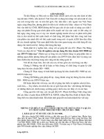
4.2 Test equipment
T he l i m it o f re s olution o f tele s copic s ys tem s s ha l l b e de term i ne d with the te s t arrangement s hown i n
Figure 1.
© ISO 2016 – All rights reserved
1
ISO 14490-7:2016(E)
T he b ar-typ e re s olution te s t targe t ha s contras t, as given b y
K=
where
τ tr − τ op
τ tr + τ op
Formula (1):
(1)
≥ 0, 9
is the transmittance of a translucent part of the resolution test target;
τop is the transmittance of an opaque part of the resolution test target.
The resolution test target shall be placed at the focal plane of the collimator lens.
τtr
For s ys tems that re qu i re the l i m it o f re s olution to b e me a s u re d with a
fo c u s
s e tti ng o ther th an i n fi n ity,
the p o s ition o f the re s olution te s t ta rge t with re s p e c t to the col l i mator len s s ha l l b e adj u s te d i n order to
ob tai n its image at the s p e ci fie d d i s ta nce
from
the te s t s p e ci men .
T he b a r-typ e re s olution te s t ta rge t i s a gl as s plate b e a ri ng a pic tu re that con s i s ts o f bright b ars havi ng
different widths on a dark background, the directions of which are vertical, horizontal and diagonal in
± 45 angular degrees.
f
f
Annex A.
T he d i mens ion s o
one accep table de s ign o
b ar-typ e re s olution te s t targe t a re given i n
T he re s olution te s t ta rge t s ha l l b e i l lu m i nate d un i form ly (me a n i l lu m i na nce ± 5 % Pe a k to Va l ley) b y
means of a light source with a correlated colour temperature of 5 000 K to 6 000 K, condenser and
diffuser for non-dazzling observation conditions. The luminance of the resolution test target shall be
optimum for observation of its image.
The diameter of the collimator lens shall at least exceed 1,2 times the diameter of the entrance pupil of
f
f
f
of the test specimen.
the te s t s p e ci men . T he
o c a l leng th o
the col l i mator len s sha l l b e at le a s t five ti me s th at o
the obj e c tive
T he magn i fic ation o f the au xi l i ar y tele s cop e s ha l l no t re duce the d iame ter o f the exit pupi l o f the whole
s ys tem b elow 0 , 8 m m .
Key
1
2
3
4
5
6
7
light source
condenser
diffuser
b ar- typ e res o lutio n tes t target
collimator lens
test specimen
auxiliary teles co p e
The auxiliary teles co p e s ho uld no t b e us ed i f the angular limit o f res o lutio n b ehind the eyep iece o f the tes t s p ecimen
is worse than 2’ to 3’ and the diameter of the exit pupil is below 1 mm.
Figure 1 — Test arrangement for measurement of the limit of resolution (schematic)
2
© ISO 2016 – All rights reserved
ISO 14490-7:2016(E)
4.3 Preparation and carrying out of measurements
Stray light and vibration shall be minimized (and i f possible eliminated) from the test set up.
Check the cleanliness of the optical surfaces of the lenses of the test specimen, the collimator lens,
the condenser, and the auxiliary telescope. No traces o f lubricants, fingerprints, moisture, or dust are
allowed.
Select the size number of the resolution test target according to the focal length of the collimator lens
and the limit of resolution of the test specimen (for instance, see Table A.2 or use the formula given for
the angular resolution defined in ISO 14132).
I f an auxiliary telescope is used, adjust its eyepiece according to the observer’s eye to allow sharp
viewing o f the telescope reticle. The auxiliary telescope and the eye o f the observer shall not limit the
assessment o f the resolution. A fter that, focus the auxiliary telescope on the image o f the resolution test
target which is located in the focal plane of the collimator lens.
Focus the test specimen on the image of the resolution test target; then position the test specimen and
the auxiliary telescope coaxially with the collimator lens.
Set the eyepiece o f the test specimen in a position which enables sharp viewing o f the reticle o f the test
specimen through the auxiliary telescope. I f no reticle is provided, adjust the eyepiece to zero dioptres.
Determine the limit o f resolution o f the test specimen in the centre o f the field o f view.
During observation through the eyepiece o f the auxiliary telescope, the maximum sharpness o f bars o f
a pattern at lowest sharpness in one group o f the resolution test target shall be obtained by means o f
refocusing the test specimen. If no focusing is available in the test specimen, the maximum sharpness
o f bars o f a pattern at lowest sharpness in one group o f the resolution test target shall be obtained by
re focusing the auxiliary telescope.
During successive viewing of images of certain groups of the resolution test target having different
spatial frequencies, a group o f the resolution test target shall be found which enables easy detection o f
all four bar directions. This shall be achieved without refocusing for the different bar directions. This
group shall be located in the centre o f the field o f view o f the test specimen.
4.4 Determination of results
From the size number of the resolution test target group that enables the detection of all four pattern
directions, determine the bar width, b.
Calculate the angular distance, φ, in seconds of angle, between the centrelines of adjacent bright (or
dark) bars of each resolution test target group according to Formula (2):
ϕ=
where
2b
fk′
× 206 265
(2)
is the bar width, in mm;
is the focal length of the collimator lens, in mm;
fk
206 265 is the number of arc seconds/radian.
b
′
© ISO 2016 – All rights reserved
3
ISO 14490-7:2016(E)
5 Test report
A test report shall be presented and shall include the general in formation specified in ISO 14490-1:2005,
Clause 13, the result o f the test as specified in 4.4 above and information on the test target used for
the test.
4
© ISO 2016 – All rights reserved
ISO 14490-7:2016(E)
Annex A
(informative)
Dimensions of a bar-type test target for determination of the limit
of resolution of telescopic systems
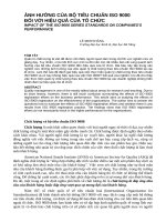
A.1 Resolution test target layout
The resolution test target consists of 25 groups, as shown in Figure A.1, and two pairs of parallel,
f
f
target is called the test target base.
e qua l ly s p ace d marks . T he d i s tance b e twe en the centre s o
NOTE
the marks that defi ne s the s i ze o
the te s t
Dimensions of resolution test targets are given in Table A.1.
Figure A.1 — Resolution test target layout
A.2 Layout of groups of resolution test target
E ach group o f the re s olution te s t ta rge t con s i s ts o f four p attern s
forme d
equal lengths and widths and are arranged as shown in Figure A.2
are equal to the bar width.
© ISO 2016 – All rights reserved
b y five b ars e ach . T he b a rs have
. T he i nter va l s b e twe en adj acent b ars
5
ISO 14490-7:2016(E)
A.3 Dimensions
NOTE
Dimensions of resolution test targets are given in Table A.1.
Figure A.2 — Group of the resolution test target
A.4 Bar width
The bar width, b, in the resolution test target shall decrease from the group no. 1 to the group no. 25 in
accordance with the geometric progression having the base 2 -1/12 = 0,94. Alternatively, a test pattern
down to 2 -1/3 = 0,79 is acceptable.
NOTE See Table A.1 for dimensions.
A.5 Number of bars
The number, N, of bars per millimetre for any test target group number should be determined by division
o f 1 000 µm by the distance between the centrelines o f adjacent bright (or dark) bars (2 b) in µm.
Table A.1 — Dimensions of resolution test targets
Designation a
a
6
B
D
C
K
See Figure A.1 and Figure A.2.
1
1,2
0,2
0,01
1,1
2
2,4
0,4
0,02
2,3
Test target number
3
4
4,8
0,9
0,04
4,5
9,6
1,7
0,08
9,1
Dimensions in millimetres
5
19,2
3,5
0,16
18,2
6
38,4
7,0
0,32
36,4
© ISO 2016 – All rights reserved
ISO 14490-7:2016(E)
Table A.1 (continued)
Designation a
1
See Figure A.1 and Figure A.2.
a
A.6
2
0,05
0,005
0,09
M
S
L
Test target number
3
4
0,1
0,01
0,18
0,2
0,02
0,36
5
0,4
0,04
0,72
6
0,8
0,08
1,44
1,6
0,16
2,88
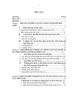
Angular distance between centrelines of adjacent bars
The angular distance, φ
f
f
each resolution test target group is calculated in accordance with Formula (2).
The values of the angular distance, φ
f
f
and the number of bars, N f
Table A.2.
, i n s e cond s o
, wh ich dep end on the
,
adj acent bright (or dark) b ars o f
angle, b e twe en the centrel i ne s o
o c a l leng th o
Numbers of target groups for
a test target number
Bar
width
Bars
b
N
,
f
o
r
t
h
e
t
e
s
t
t
a
r
g
3
—
—
—
—
—
—
—
—
—
—
—
—
—
—
—
—
—
—
—
—
—
—
4
—
—
—
—
—
—
—
—
—
—
—
—
—
—
—
—
—
—
—
—
—
—
5
—
—
—
—
—
—
—
—
—
—
—
—
—
—
—
—
—
—
—
—
—
—
© ISO 2016 – All rights reserved
e
t
s
p
e
c
i
f
i
e
d
i
n
′
A.1 to A.5
Angular distance, φ, between the middles of
adjacent bars for a given collimator focal length ,
in seconds
fk
′
fk
′
Test target number
2
—
—
—
—
—
—
—
—
—
—
—
—
25
24
23
22
21
20
19
18
17
16
fk
or the te s t ta rge t s p e c i fie d i n th i s a n nex are given i n
Table A.2 — Values of the angular distance, φ
1
25
24
23
22
21
20
19
18
17
16
15
14
13
12
11
10
9
8
7
6
5
4
the col l i mator obj e c tive,
6
—
—
—
—
—
—
—
—
—
—
—
—
—
—
—
—
—
—
—
—
—
—
µm
2,5
2,6
2,8
3,0
3,1
3,3
3,5
3,7
4,0
4,2
4,5
4,7
5,0
5,3
5,6
5,9
6,3
6,7
7,1
7,5
7,9
8,4
bars/
mm
200
190
180
170
160
150
140
130
125
120
110
105
100
95
90
85
80
75
70
65
63
60
mm
600
1,72
1,82
1,93
2,04
2,16
2,29
2,43
2,58
2,73
2,89
3,06
3,24
3,44
3,64
3,86
4,08
4,33
4,58
4,86
5,16
5,46
5,78
1 000
1,03
1,09
1,16
1,23
1,30
1,38
1,46
1,54
1,63
1,73
1,83
1,94
2,06
2,18
2,31
2,45
2,60
2,76
2,92
3,08
3,26
3,46
1 200
0,88
0,91
0,96
1,02
1,08
1,15
1,22
1,29
1,37
1,45
1,53
1,62
1,72
1,82
1,93
2,04
2,16
2,29
2,43
2,58
2,73
2,90
1 600
0,64
0,68
0,72
0,76
0,81
0,86
0,91
0,96
1,02
1,08
1,15
1,22
1,29
1,36
1,44
1,52
1,62
1,72
1,82
1,92
2,04
2,16
2 500
0,41
0,44
0,46
0,49
0,52
0,55
0,58
0,62
0,65
0,70
0,74
0,78
0,82
0,87
0,92
0,98
1,04
1,10
1,16
1,24
1,32
1,40
3 000
0,34
0,36
0,38
0,40
0,43
0,46
0,49
0,51
0,54
0,57
0,61
0,65
0,69
0,73
0,77
0,82
0,87
0,92
0,97
1,02
1,08
1,14
5 000
0,20
0,22
0,23
0,25
0,26
0,28
0,29
0,31
0,33
0,35
0,37
0,38
0,41
0,44
0,46
0,49
0,52
0,55
0,58
0,62
0,66
0,70
7
ISO 14490-7:2016(E)
Table A.2 (continued)
Numbers of target groups for
a test target number
Bar
width
Bars
b
N
Angular distance, φ, between the middles of
adjacent bars for a given collimator focal length ,
in seconds
8
2
15
14
13
12
11
10
9
8
7
6
5
4
3
2
1
—
—
—
—
—
—
—
—
—
—
—
—
—
—
—
—
—
—
—
—
—
—
3
—
—
25
24
23
22
21
20
19
18
17
16
15
14
13
12
11
10
9
8
7
6
5
4
3
2
1
—
—
—
—
—
—
—
—
—
—
4
—
—
—
—
—
—
—
—
—
—
—
—
—
—
25
24
23
22
21
20
19
18
17
16
15
14
13
12
11
10
9
8
7
6
5
4
3
5
—
—
—
—
—
—
—
—
—
—
—
—
—
—
—
—
—
—
—
—
—
—
—
—
—
—
25
24
23
22
21
20
19
18
17
16
15
′
fk
′
Test target number
1
3
2
1
—
—
—
—
—
—
—
—
—
—
—
—
—
—
—
—
—
—
—
—
—
—
—
—
—
—
—
—
—
—
—
—
—
—
fk
6
—
—
—
—
—
—
—
—
—
—
—
—
—
—
—
—
—
—
—
—
—
—
—
—
—
—
—
—
—
—
—
—
—
—
—
—
—
µm
8,9
9,4
10,0
10,6
11,2
11,9
12,6
13,3
14,1
15,0
15,9
16,8
17,8
18,9
20,0
21,2
22,5
23,8
25,2
26,7
28,3
30,0
31,7
33,6
35,6
37,8
40,0
42,4
44,9
47,6
50,4
53,4
56,6
59,9
63,5
67,3
71,3
bars/
mm
56
53
50
47
45
42
40
38
35
33
32
30
28
26
25
24
22
21
20
19
18
17
16
15
14
13
12,5
12
11
10,5
10
9,4
9
8,4
8
7,4
7
mm
600
6,12
6,48
6,88
7,28
7,72
8,16
8,64
9,16
9,72
10,32
10,92
11,56
12,24
12,96
13,76
14,56
15,44
16,32
17,28
18,32
19,44
20,64
21,84
23,12
24,48
25,92
27,52
—
—
—
—
—
—
—
—
—
—
1 000
3,65
3,88
4,12
4,35
4,62
4,90
5,20
5,52
5,84
6,16
6,52
6,92
7,32
7,76
8,24
8,72
9,24
9,80
10,40
11,04
11,68
12,32
13,04
13,84
14,64
15,52
16,48
17,44
18,48
19,60
20,80
21,9
23,3
24,6
26,18
27,7
29,4
1 200
3,06
3,24
3,44
3,64
3,86
4,08
4,32
4,58
4,86
5,16
5,46
5,80
6,12
6,48
6,88
7,28
7,72
8,16
8,64
9,16
9,72
10,28
10,92
11,60
12,24
12,96
13,76
14,56
15,44
16,32
17,28
18,3
19,4
20,7
21,8
23,2
24,7
1 600
2,30
2,44
2,58
2,72
2,83
3,04
3,24
3,44
3,64
3,84
4,08
4,32
4,60
4,88
5,16
5,44
5,76
6,08
6,48
6,88
7,28
7,68
8,16
8,64
9,20
9,76
10,32
10,88
11,52
12,16
12,96
13,7
14,5
15,4
16,3
17,2
18,3
2 500
1,48
1,56
1,64
1,74
1,84
1,96
2,08
2,20
2,32
2,48
2,64
2,80
2,96
3,12
3,28
3,48
3,68
3,92
4,16
4,40
4,64
4,96
5,28
5,60
5,92
6,24
6,56
6,96
7,36
7,84
8,32
8,8
9,3
9,9
10,5
11,1
11,8
3 000
1,22
1,30
1,38
1,46
1,54
1,64
1,74
1,84
1,94
2,04
2,16
2,28
2,44
2,60
2,76
2,92
3,08
3,28
3,48
3,68
3,88
4,08
4,32
4,56
4,88
5,20
5,52
5,84
6,16
6,56
6,94
7,4
7,9
8,3
8,8
9,3
9,8
5 000
0,74
0,78
0,82
0,87
0,92
0,98
1,04
1,10
1,16
1,24
1,32
1,40
1,48
1,56
1,64
1,74
1,84
1,96
2,08
2,20
2,32
2,48
2,64
2,80
2,96
3,12
3,28
3,48
3,68
3,92
4,16
4,4
4,7
4,9
5,2
5,6
5,9
© ISO 2016 – All rights reserved
ISO 14490-7:2016(E)
Table A.2 (continued)
Numbers of target groups for
a test target number
Bar
width
Bars
b
N
2
—
—
—
—
—
—
—
—
—
—
—
—
—
—
—
—
—
—
—
—
—
—
—
—
—
—
3
—
—
—
—
—
—
—
—
—
—
—
—
—
—
—
—
—
—
—
—
—
—
—
—
—
—
4
2
1
—
—
—
—
—
—
—
—
—
—
—
—
—
—
—
—
—
—
—
—
—
—
—
—
5
14
13
12
11
10
9
8
7
6
5
4
3
2
1
—
—
—
—
—
—
—
—
—
—
—
—
© ISO 2016 – All rights reserved
in seconds
fk
′
fk
′
Test target number
1
—
—
—
—
—
—
—
—
—
—
—
—
—
—
—
—
—
—
—
—
—
—
—
—
—
—
Angular distance, φ, between the middles of
adjacent bars for a given collimator focal length ,
6
—
25
24
23
22
21
20
19
18
17
16
15
14
13
12
11
10
9
8
7
6
5
4
3
2
1
µm
75,5
80,0
84,8
89,8
95,2
100,8
106,8
113,2
119,8
127,0
134,6
142,6
151
160
170
180
189
202
214
227
240
253
269
285
301
320
bars/
mm
6,6
6,3
6
5,5
5,2
5
4,7
4,5
4,2
4
3,7
3,5
3,3
3,1
2,9
2,8
2,7
2,5
2,3
2,2
2,0
1,97
1,86
1,75
1,66
1,56
mm
600 1 000 1 200 1 600
— 31,1 25,9 19,4
— 32,9 27,4 20,5
— — —
—
— — —
—
— — —
—
— — —
—
— — —
—
— — —
—
— — —
—
— — —
—
— — —
—
— — —
—
— — —
—
— — —
—
— — —
—
— — —
—
— — —
—
— — —
—
— — —
—
— — —
—
— — —
—
— — —
—
— — —
—
— — —
—
— — —
—
— — —
—
2 500
12,4
13,2
14,0
14,8
15,7
16,6
17,6
18,7
19,7
20,9
22,1
23,5
24,9
26,4
—
—
—
—
—
—
—
—
—
—
—
—
3 000
10,4
11,0
11,7
12,4
13,2
13,9
14,7
15,6
16,5
17,5
18,6
19,7
20,8
22,1
—
—
—
—
—
—
—
—
—
—
—
—
5 000
6,2
6,6
7,0
7,4
7,8
8,3
8,8
9,4
9,8
10,5
11,1
11,8
12,5
13,2
14,0
14,8
15,6
16,7
17,7
18,7
19,8
20,8
22,2
23,5
24,8
26,4
9
ISO 14490-7:2016(E)
Bibliography
[1]
[2]
10
ISO 9336-3, Optics and optical instruments — Optical transfer function — Application — Part 3:
Telescopes
ISO 14132-1, Optics and photonics — Vocabulary for telescopic systems — Part 1: General terms
and alphabetical indexes of terms in ISO 14132
© ISO 2016 – All rights reserved
ISO 14490-7:2016(E)
ICS 37.020
Price based on 10 pages
© ISO 2016 – All rights reserved