Tiêu chuẩn iso 11519 3 1994 + amd1 1995 scan
Bạn đang xem bản rút gọn của tài liệu. Xem và tải ngay bản đầy đủ của tài liệu tại đây (1.29 MB, 117 trang )
4851403 Ob09798 832
INTER NATIO NAL
STANDARD
IS0
11519-3
First edition
1994-06-15
AMENDMENT 1
1995-04-01
Road vehicles - Low-speed serial data
communication Part 3:
Vehicle area network (VAN)
AMENDMENT 1
Véhicules routiers - Communication en série de données à
vitesse basse Partie 3: Réseau local de véhicule (VAN)
AMENDEMENT 1
Reference number
I S 0 1151 9-3:1994/Amd.l:1995(E)
4 8 5 1 9 0 3 Ob09777 7 7 9
IS0 11519-3:1994/Amd.1:1995(E)
Foreword
I S 0 (the International Organization for Standardization) is a worldwide
federation of national standards bodies ( I S 0 member bodies). The work of
preparing international Standards is normally carried out through I S 0
technical committees. Each member body interested in a subject for which
a technical committee has been established has the right to be
represented on that committee. International organizations, governmental
and non-governmental, in liaison with ISO, also take part in the work. I S 0
collaborates closely with the International Electrotechnical Commission
(IEC)on all matters of electrotechnical standardization.
Draft International Standards adopted by the technical committees are
circulated to the member bodies for voting. Publication as an International
Standard requires approval by at least 75 % of the member bodies casting
a vote.
Amendment 1 to International Standard I S 0 11519-3:1994 was prepared
by Technical Committee lSO/TC 22, Road vehicles, Subcommittee SC 3,
Electrical and electronic equipment.
I S 0 11519 consists of the following parts, under the general title Road
vehicles - Low-speed serial data communication :
- Part
I: General and definitions
- Part 2: Low-speed controller area network (CAN)
-
O
Part 3: Vehicle area network (VAN)
I S 0 1995
All rights reserved Unless otherwise specified, no part of this publication may be reproduced
or utilized in any form or by any means, electronic or mechanical, including photocopying and
microfilm, without permission in writing from the publisher
International Organization for Standardization
Case postale 56 0 CH-1 21 1 Genève 20 0 Switzerland
Printed in Switzerland
II
W 4 8 5 3 9 0 3 Ob09800 230
IS0 115193:1994/Amd.l:1995(E)
o IS0
Road vehicles - Low-speed serial data communication Part 3:
Vehicle area network (VAN)
AMENDMENT I
Page iv
Insert new page v and the following Introduction
Introduction
Validation tests on vehicles have been conducted on the basis of I S 0 11519-3:1994. The speed of data
transmission has been increased up to 250 kTS/s with the same reliability providing that:
-
Filter description and system characteristics are more precisely given, and
- parameter specifications of the transceiver are improved.
Amendment 1 to IS0 11519-3 details the necessary changes to the 1994 Standard.
Page 79
Add a new clause before clause 8, to read as follows.
7.6 Alternative up to 250 kTSIs
This clause describes the network interface up to 250 kTS/s.
The definition of TS (Time Slot) is according to clause 7.2.3 Bit encoding of I S 0 11519-3 (VAN).
250 kTS/s is corresponding to 125 kbit/s in Manchester coding and 200 kbit/s in Enhanced Manchester coding.
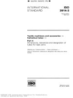
7.6.1 System description
7.6.1.1 Functional block diagram
This block diagram is given in figure 52.
1
= 4851903 Ob09801 157 =
~
IS0 11519-3:1994/Amd.1:1995(E)
o IS0
TRANSCEIVER
Driver
we
irec
vcc
I
w
I
irec
Idom
I
Idom
.
I
Receiver
I
FILTER
L
0
I
DL
I
I
Polarization
c
Figure 52
2
-250 kTS/s VAN bus interface
Pol
W 4851903 Ob09802 093
oIS0
IS0 11519-3:1994/Amd.1:1995(E)
7.6.1.2 Filter section
The diagram is given in figure 53, together with the parameters.
Data
c2
CI
-
R2
I
DataB
Parameter
Recommended value
-
c1
100 pF
c2
120 pF
R1
100
R2
1800
Comments
Tolerance
2 50 V
I
2 25
10 %
n
V
114 W continuous
i
1/16 W continuous,
n
I
114 W continuous
1 . 2 5 W during 4 0 0 ms
I
Figure 53 -250 kTS/s filter
7.6.1.3 Cable characteristics
Value
Test condition and description
Parameter
min.
1.
Cg-data
I Overall
l
capacitance between ground and Data
o
I
1
typical
I max. I
I
I
200
Unit
pF/module
I
~
Cg-dataB
Cdata-dataB
Coverall
Overall capacitance between ground and DataB
O
200
pF/module
Overall capacitance between Data and DataB
O
100
pF/module
= Cg-data + CgdataB + 2 CgData-DataB; by node connected and
2 . 0 V offset ground in nominal mode or 0,7 V offset in degraded
O
200
pF/module
Overall cable length
O
20
m
mode.
~
Lcable
Overall resistor isolation between ground and data
RISOLg-data
I RISOLg-dataB I Overall resistor isolation between Data and DataB
I RISOLdata-dataB I Overall resistor insulation between Data and DataB
kn
50
~~
~
~~
~
1 5 0 1 -
r2,r
Overall serial resistor of Data or DataB between nodes
RCOND
T
I
T
T
~knl
~
O
R
4
7.6.1.4 System characteristics
7.6.1.4.1 Number of nodes connected to the network
I
Parameter
mode
I
Test condition and description
~~
Number of nodes connected to network
I
Value
min.
I
typical
I
max.
I
Unit
~
2
12
1
node
3
f
M 4853903 Ob09803 T 2 T M
o IS0
IS0 11519-3:1994/Arnd.l:1995(El
7.6.1.4.2 Timing characteristics
Parameter
Value
Test condition and description
TS
Time Slot duration without resynchronization (DE input)
TDelay
Propagation delay time between DE logical input for one node to
RO, R1, and R2 logical outputs from any node
Tsample
Sample point of protocol controller
min.
typical
max.
Unit
3,96
4
4,04
W
O
0,6
1,2S
W
12/16
12/16
12/16
TS
Number of pulses
IS0 pulse type
Magnitude no load
Duration
Source impedance
Period
5
V, = 36,5 V
Td = 400 ms
R ì = 2 n
1 min
5
1
V, = -50 V
5 s
50
ta = 2 ms
Ri
=
10
7.6.1.4.4 Continuous stress capability (automotiveapplication)
The network interface is designed to withstand - 24 V and +24 V voltages on Data and DataB lines.
7.6.1.4.5 Ground offset between nodes
I
1
Parameter
I
Value
Test condition and description
min.
~~
~
I
I
Offset between the 2 nodes in nominal mode
(for worst case parameters of cable and interface)
~
Vnode-deg
I
Offset between the 2 nodes in degraded mode
(for worst case parameters of cable and interface)
-2
-0,7
I
I
1
typical
O
I
I
1
max.
+2
+0,7
I
I
1
unit
V
V
~
Nominal mode: The network uses Data and DataB line for communication.
Degraded mode: In this case, one line is broken-down and the network uses Data or DataB line for communication.
7.6.2 Transceiver description
7.6.2.1 Driver section
b
I
Parameter
Irec
l
I
Test condition and description
i
Value
min.
I
twical
I max. I
unit
+1,8
DE = 1; Vdata = -5 V to +3,75 V; VdataB = + 1 , 2 5 V to +10 V
+1,6
+2,0
mA
DE = 1; Vdata = +3,75 V to +5 V; VdataB = +O V to + 1 , 2 5 V
-0,lO
+2,0
mA
-0,lO
+0,10
mA
DE = 1; Vdata = +5
v
to +i0 V; VdataB = -5 V to O V
~~
DE = O; Vdata = +1.25 V to +10 V; VdataB = -5 V to +3,75 V
Idom
DE = O; Vdata = O V to + 1 , 2 5 V; VdataB = +3,75 V to +5 V
DE = O; Vdata = -5 V to O V; VdataB = +5 V to
+lo
V
DE = 1; Vdata = -5 V to +10 V; VdataB = -5 V to +10 V
Overshot
4
+60
mA
-0.10
+60
mA
-0,lO
+o, 10
mA
-0.10
+0,10
mA
10
mA
-5
+5
%
+45
Current overshot during transition recessive --> dominant
+50
M- I
Static matching of current output
TON
Propagation delay of dominant current from recessive state to
dominant state
200
ns
TOFF
Propagation delay of dominant current from dominant state to
recessive state
200
ns
I
485L903 Ob09804 966
o IS0
IS0 11519-3:1994/Amd.l:1995(E)
7.6.2.2 Receiver section
Parameter
VMCR
ZMC
ZMD
CMC
CMD
I
I
I
I
I
OFFr
HYSdif
HYSSr
TDEL
TEDH
Value
Test condition and description.
1
I
min. I tvoicai I max. I
Common mode
I
0,5
I
Common mode impedance
I
loo
I
Differencial mode impedance
I
100
Input capacitance between input and ground
I
Differential input capacitance between inputs
I
Unit
I
4.5
I
v
I
10
I
PF
10
I
PF
I
I
I
I
R 1 and R2 comparators offset
-25
O
+2 5
mv
Differential comparator input hysteresis
150
200
250
mV
R1 and R2 comparator input hysteresis
150
200
250
mV
150
ns
I
Propagation delay for high to low transition, input
overdrive 5 0 mV
l
Propagation delay for low to high transition, input
overdrive 5 0 mV
7.6.2.3 Polarization section
Parameter
Value
Test condition and description
min.
ZGT
Output impedance POL used by filter
I 3 mA output POL current
typical
Frenquency = 1MHz
max.
Unit
200
n
100
n
VGTint
Internal reference for R1 and R2 used by comparators
2,315
2,5
2,625
V
VGText
Output voltage POL I 2 mA used by filter
2,315
2.5
2,625
V
Frequency
S
1 kHz
5
m
Li851703 Ob07805 8 T 2
IS0 11519-3:1994/Amd.l:1995(E)
o IS0
ICs 43 040 10
Descriptors: road vehicles. electronic equipment. data communication equipment, data processing, information interchange, local area
networks, vehicle area networks, data transmission, data link layer, physical layer
Price based on 5 pages
IS0 LI1519 PT*3 94 D 4851903 0565263 77T D
I NTERNATI ONAL
STANDARD
IS0
11519-3
First edition
1994-06-15
Road vehicles - Low-speed serial data
communication
-
Part 3:
Vehicle area network (VAN)
Véhicules routiers - Communication en série de données à basse
vitesse Partie 3: Réseau local de véhicule (VANI
Reference number
I S 0 11519-3:1994(E)
I S 0 11519 P T * 3 94
48511903 05b52b4 826 W
IS0 11519-3:1994(E)
Contents
Page
1
Scope ..............................................................................................
1
2
Normative references .....................................................................
1
3
Definitions and abbreviations
....................................................
1
...............................................................................
1
...............................................................
3
......................................................
4
...................................................................................
4
3.1
Definitions
3.2
List of abbreviations
4
Presentation of architecture
4.1
General
4.2
Reference to OS1 model
........................................................
5
Description of LLC sublayer
......................................................
6
5.1
LLC service specifications
......................................................
6
5.2
Error management at LLC level
5.3
Error recovery management at LLC level
5
...........................................
10
............................
10
Description of the MAC sublayer
............................................
10
6.1
Specification of MAC service
...............................................
10
6.2
Structure of MAC frames
6.3
Specification of Medium Access Method (MAC)
6
7
.....................................................
Description of physical layer
23
................. 42
...................................................
48
..........................................
49
7.1
Specification of physical service
7.2
Encoding/decoding and synchronization sublayer
7.3
Line transmitter/receiver
7.4
Connector
7.5
Communication medium
................ 53
......................................................
76
.............................................................................
79
......................................................
79
...............................................................
79
8.1 At LLC sublayer level
...........................................................
79
8.2 At MAC sublayer level
..........................................................
79
8
Electrical parameters
O I S 0 1994
All rights reserved . No part of this publication may be reproduced or utilized in any form or
by any means. electronic or mechanical. including photocopying and microfilm. without permission in writing from the publisher .
International Organization for Standardization
Case Postale 56 CH-121 1 Genève 20 Switzerland
Printed in Switzerland
II
IS0 33539 PT*3 9 4
4853903 0565265 7 b 2
=
IS 0 11519-3:1994(E)
8.3
Conformance
9
...........................................................
80
...........................................................................
83
At physical layer level
9.1
Conformance at MAC layer level
.........................................
83
9.2
Conformance a t physical layer level: Line transmitter/receiver
......................................................................................
tests
84
Annexes
...............................
A
Setup example for Baud Rate Multiplier
B
Setup example of realization of interface between physical layer and
data link layer
.........................................................................
90
.
89
B1
Interface position/OSI model
...............................................
90
B.2
Definition of dialogue signals between binary and electric
encoding/decoding sublayers
...............................................
90
.......................................
90
....................................................
90
8.3
Coding bit and symbol (see 7.2.3)
B.4
Character synchronization
B.5
Signals exchange rules between PL1 and PL2 sublayers
B.6
Exceptions to this signal exchange rules
B.7
Timing diagram for various dialogue signals between PL1 and PL2
sublayers
..............................................................................
96
............................
... 96
96
...
111
IS0 LL519 P T * 3 94
4851903 05652bb b T ï
I S 0 11519-3:1994(E)
Foreword
I S 0 (the International Organization for Standardization) is a worldwide
federation of national standards bodies (IS0 member bodies). The work
of preparing International Standards is normally carried out through I S 0
technical committees. Each member body interested in a subject for
which a technical committee has been established has the right to be
represented on that committee. International organizations, governmental
and non-governmental, in liaison with 60, also take part in the work. I S 0
collaborates closely with the International Electrotechnical Commission
(IEC) on all matters of electrotechnical standardization.
Draft International Standards adopted by the technical committees are
circulated to the member bodies for voting. Publication as an International
Standard requires approval by at least 75 % of the member bodies casting
a vote.
international Standard I S 0 1 1519-3 was prepared by Technical Committee
ISOflC 22, Road vehicles, Sub-Committee SC 3, Electrical and electronic
equipment.
I S 0 11519 consists of the following parts, under the general title Road
vehicles - Low-speed serial data communication:
- Part I: General and definitions
- Part
2: Low-speed controller area network (CAN)
- Part 3: Vehicle area network
- Part 4: Class
(VAN)
B data communication network interface (J1850)
Annexes A and B form an integral part of this part of I S 0 11519.
iv
=
IS0 LL517 P T * 3 9 4
= 4851903 05b52b7
535
INTERNATIONAL STANDARD
-
Road vehicles
Low-speed serial data
communication
Part 3:
Vehicle area network (VAN)
1 Scope
This part of I S 0 11519 specifies the data link layer and the physical layer of the Vehicle Area Network (VAN),
communications network up to 125 kbit/s, for road vehicle application. The VAN is an access-method-oriented
multimaster-multislave which allows optimized requesthesponse management by special method of handling a
remote transmission request (retaining access to the medium to allow insertion of a response).
This part of I S 0 11519 defines the general architecture of the low-speed communication network up 125 kbits/s
and the content of the data link layer, and the physical layer for transmission between different types of electronic
modules on board road vehicles.
2
Normative references
The following standards contain provisions which, through reference in this text, constitute provisions of this part
of I S 0 1151 9. At the time of publication, the editions indicated were valid. All standards are subject to revision,
and parties to agreements based on this part of I S 0 11519 are encouraged to investigate the possibility of applying
the most recent editions of the standards indicated below. Members of IEC and I S 0 maintain registers of currently
valid International Standards.
ISOTTR 8509: 1987, Information processing systems - Open Systems Interconnection - Service conventions.
IS0 8802-2:1989, Information processing systems - Local area networks
- Part 2: Logical link control.
3 Definitions and abbreviations
3.1 Definitions
For the purposes of this part of IS0 11519, the following definitions apply.
3.1.1 acknowledgement field (ACKI: Field used by a module concerned to indicate correct interpretation of the
frame by a receiver.
1
IS0 11519-3:1994(E)
3.1.2
autonomous module: Module which can initiate data sending over the transmission medium.
3.1.3 bitwise arbitration: Arbitration technique which allows a priority message to take precedence on the bus
and dominate other messages of lower priority with which it collides. The collision is thus not destructive for the
highest-priority message. This bitwise arbitration technique is based on the use of dominant and recessive states
on the bus, with the dominant states taking precedence over the recessive bits.
In the event of a collision in the arbitration field (simultaneous sending of recessive and dominant bits), only those
modules sending a dominant bit will keep on transmitting, while the others will cease to transmit. This process is
repeated for each bit of the arbitration field.
Bus value
3.1.4
The bus can take 2 electrical states:
dominant (D) corresponds to a logic level "O" ,
recessive (R) corresponds to a logic level "1 " .
code violation: Any error that converts a bit or other physical symbol into an out-of-code symbol.
3.1.5 collision; interference: Physical phenomenon that occurs when several signals are superimposed on one
another, whether they are of internal origin (modules connected to the bus) or external origin (noise).
3.1.6 collision detection: Collision detected by a sending module when interference occurs on the bus and
modifies the signal transmitted (more precisely, the signal received is different from the signal sent).
3.1.7 command field (COM): Field containing command information associated with the frame
3.1.8 contention: Situation that arises when several modules start transmitting simultaneously on the communication bus.
3.1.9 data field (DAT): Part of the frame containing data. The field consists of a whole number of bytes
3.1.10 data transmission: Process by which encoded data can be sent over a transmission medium sequentially
in binary form.
3.1.11 end of data (EOD): Part of the frame indicating the end of data. The EOD is located just after the Frame
Check Sequence (FCS).
3.1.12 end of frame (EOF): Part of the frame indicating the end of a frame.
3.1.13 extensibility: Situation where modules can be added to the network without having to change the software or hardware of any module for an existing application, within the limits of the communication layers specified
in this document.
3.1.14 MAC frame: Sequence of fields containing either:
a start of frame field;
an identifier field;
a command field;
a data field;
a frame check sequence field;
an end of data field;
an acknowledgement field;
an end of frame field.
or
a start of frame field;
an identifier field;
a command field;
a frame check sequence field;
an end of data field;
an acknowledgement field;
an end of frame field.
Each frame is separated by an interframe spacing field.
2
I S 0 11519 P T x 3 94
4851903 0565267 306
IS0 11519-3:1994(E)
3.1.15 frame check sequence (FCS): Part of the frame which checks its integrity. In the present case, this
function is performed by means of a Cyclic Redundancy Check (CRC).
3.1.16 identifier field (IDEN): Part of the frame following the SOF, which identifies and specifies the data conveyed in the frame.
3.1.17 interframe spacing (IFS): Minimum time interval locally required between the sending of two consecutive frames, which is controlled by the MAC sublayer.
3.1.18 module: Physical entity connected to the network, capable of receiving and/or sending data via the medium.
3.1.19 remote transmission request: By sending a data request, a module that wishes a data unit can request
another module to send it the corresponding data. The data unit can be sent either immediately in the same frame
or later in a separate frame identified by the same identifier.
3.1.20 slave module: Module which can
- receive data
- send data when requested, by means of an in-frame response mechanism.
3.1.21 start of frame (SOF): Part of the frame which indicates the start of the frame and synchronizes the receiving modules' clocks.
3.1.22 synchronous access module: Module which can initiate transmission only after a Start of Frame
character appears on the bus.
(SOF)
3.2 List of abbreviations
AC K
Acknowledge
ADT
Acknowledged Data Transfer
BR
Bit Rate
BT
Bit Time
D
Dominant State
DL
Data Link
EOD
End Of Data
EOF
End Of Frame
FCS
Frame Check Sequence
IFS
Interírame Spacing
LLC
Logical Link Control
LSB
Least Significant Bit
LSDU
Link Service Data Unit
3
IS0 11519 P T * 3 94 W 48.51903 0565270 02T
=
IS0 11519-3:1994(E)
MAC
Medium Access Control
MDI
Medium Dependent Interface
MSB
Most Significant Bit
NADT
Not Acknowledged Data Transfer
os1
Open Systems Interconnection
PL
Physical Layer
PLS
Physical SignaIIi ng
PMA
Physical Medium Attachment
Q/R
Question/Response Frame
RD
Recessive State
RAK
Request Acknowledge
RT
Remote Transmission
RTR
Remote Transmission Request
SOF
Start Of Frame
TS
Time Slot
4
Presentation of architecture
4.1 General
The objectives of the VAN are to interconnect different types of electronic modules on board a vehicle and to
transmit messages having different priority levels.
The VAN is an asynchronous data transmission system which allows the transfer of packets of data.
The messages handled can be typically:
- messages of
1 byte, to write or to read from a slave peripheral module;
- messages from O to 28 bytes, to exchange parameters and/or events between the different autonomous
modules;
- long messages segmented by the user.
The document allows the possibility of interconnecting heterogeneous modules including, among others, very
simple slave modules.
The implications for the frame format and layer design are:
- the use of a special Start Of Frame field which can correct the local clocks of the simple modules and establish
a common time base;
- the possibility of chaining the response of a module in the same request frame concerning it;
- the possibility of direct in-frame acknowledgement.
4
IS0 L L 5 L 9 PTU3 9 4
4853903 05b527L Tbb
=
I S 0 11519-3:1994(E)
4.2 Reference to OS1 model
The VAN architecture complies with the I S 0 reference model for Open Systems Interconnection (OSI) with respect to the breakdown by layers. This breakdown is shown in figure 1.
D
OS1 model
Beyondscopeofdocument
hpplication
Supervisor
I
'resentation
Session
d
l
Transport
Unsuccessful
attempt count
Repeat attempt
count
I
Data encapsulation/
decapsulation
I
control function
Bit and symbol
encoding/decoding
synchronization
[
1-2
Line break
(bus status)
I
Line interface
I
1-1
I
Connector parameters
Medium parameters
Figure 1
- Breakdown by layers in accordance with OS1 model
5
I S 0 33519 P T * 3 9 4
4 8 5 3 9 0 3 O565272 9 T 2
IS0 11519-3:1994(E)
5
Description of LLC sublayer
The LLC (Logical Link Control) sublayer is the upper part of the data link layer (layer 2 of the I S 0 reference
model - see figure 1).
The objective is to provide a multipoint data transmission service, in connectionless mode.
The architecture of the VAN, described in this part of I S 0 1 1 51 9,allows two types of service which can be provided by the LLC sublayer (in accordance with the International Standard on LAN architecture, I S 0 8802-2):
- The class I LLC service which offers a data transfer service without acknowledgement: this provides a minimum level of service and requires the implementation of greatly reduced functionalities a t the LLC layer protocol level;
- The class 111 LLC service which offers, in addition to class I services (point-to-point, multipoint or broadcast
data transfer), check services on the operation of the data link (acknowledgement, flow control, sequencing
and error recovery).
Generally speaking, the LLC sublayer provides the functionalities needed for supervision of the data links and
should incorporate at its level recovery capabilities in the event of failure of a module.
The description of the services of the LLC sublayer is given in 5.1.The precise definition of LLC procedure elements required for implementation of these services is not yet contained in this part of I S 0 l 151 9.
5.1 LLC service specifications
5.1.1 Object
This subclause specifies the services which are provided by the LLC sublayer to the LLC user in the framework
of the VAN architectural model defined in this part of I S 0 1 1 51 9 (see figure 1 for the description of the layers).
5.1.2
General presentation of LLC services
The services provided by the LLC sublayer are designed to allow exchange of packets between the local user
entity (LLC user) and peer entities (LLC users) which are connected to the communication bus.
In order to provide these services, the LLC sublayer builds its functions on the services provided by the next lower
sublayer (MAC services: see 6.1).
There are three types of services provided by the LLC sublayer. All these services are connectionless oriented (¡.e.
they do not need the establishment and maintenance of a connection, see I S 0 8802-2).
5.1.2.1
Unacknowledgeddata transfer service
The unacknowledged data transfer service provides the means by which a transfer entity can send Link Service
Data Units (LSDU) to transfer entities.
This service can be used for point-to-point, multipoint or broadcast exchanges with maximum efficiency.
5.1.2.2
Acknowledged data transfer service
The acknowledged data unit exchange service provides the means by which a transfer entity can exchange Link
Service Data Units (LSDU) to another transfer entity with the guarantee that the LSDU has been transmitted correctly.
This service can be based either on an LLC-level acknowledgement mechanism LLC Type 3 when a high level of
reliability is required or on the acknowledge capability provided by the MAC sublayer (see 6.3.2.1.1).
This part of I S 0 11519 does not specify the functions of the LLC sublayer necessary to provide acknowledged data
unit exchanges (LLC type 3).
The acknowledged data transfer service is to be used for point-to-point exchanges only.
6
I S 0 11519 P T * 3 94
4853903 0565273 839
IS0 11519-3:1994(E)
5.1.2.3
Remote data transmission service
The remote data transmission service provides the means by which a transfer entity at one module can request
(consume) a data unit (LSDUI that is located (produced) at some other remote module.
This service can be used for point-to-point, multipoint or broadcast exchanges, with respect to the transferred data
units (LSDU).
This service is divided in two subservices:
- the response preparation service,
- the reply service.
5.1.3 Description of LLC service interactions
5.1.3.1 Service specification method and notation
This subclause describes the service aspects of the LLC sublayer (corresponding to the various functionalities of
the LLC sublayer provided for users located in the upper layer).
This is an abstract representation (or model) of an interface between the LLC sublayer and an LLC service user,
independent of any specific implementation.
The LLC service definition proposed hereafter complies with the I S 0 reference model: in particular, it uses the
associated service notations in ISO/TR 8509.
The service primitives used are of three types: request, indication, confirm. Their meaning is summarized below:
Request
Indication
Confirm
The request primitive is sent by a (NI-user to the (NI-layer or (NI-sublayer to request initiation of
a service.
The indication primitive is sent by the (NI-layer or (NI-sublayer to a user of the (NI-service to indicate that an event internal to the (N)-(sub-)layerhas occurred and that the event in question is
significant for the (NI-user. An indication can be triggered by a service request executed previously or by an internal event in the (NI-(sub-Ilayer.
The confirm primitive is sent by (NI-layer to a (NI-user to retrieve the results associated with the
previous service request.
The links (logical and temporal) between indication and confirm are diverse, depending basically on the characteristics of each service.
LLC service user
LLC service provider
LLC service user
Request
Confirm
Figure 2
- Schematic diagram of interactions between adjacent layers
5.1.3.2 Description of service interactions
Table 1 gives a list of the service primitives characterizing each of the LLC service elements described in this part
of IS0 11519. Subclause 5.1.3.3 gives a detailed description of each of these service primitives.
7
IS0 11519-3:1994(E)
Table 1
- List of LLC service primitives
DL-DATA.request
DL-DATAkdication
Request for unacknowledged data transfer.
I
Indication of unacknowledged data transfer.
DL-DATA.confirm
Confirm of unacknowledged data transfer.
DL-ACK-DATA. request
Request for acknowledged data transfer.
DL-ACK-DATA.indication
Indication of acknowledged data transfer.
DL-ACK-DATA.conf irm
Confirm of acknowledged data transfer.
Remote transmission service with acknowledgement
Request for remote transmission.
DL-REPLY.request
DL-REPLY.indication
I
Indication of remote transmission.
DL-REPLY.confirm
Confirm of remote transmission.
DL-REPLY-UPDATE.request
Request for response preparation.
DL-REPLY-UPDATE.confirm
Confirm of response preparation.
Reply service
DL-REPLY.request
I
Request for remote transmission.
DL-REPLYhdication
Indication of remote transmission.
DL-R EPLY.conf irm
Confirm of remote transmission.
DL-REPLY-UPDATE.request
DL-R EPLY-UPDATE.confirm
I
Request for response preparation.
Confirm of response preparation.
I S 0 1 1 5 1 9 P T * 3 94
= 4851903
0565275 b o 1
=
IS0 11519-3:1994(E)
5.1.3.3 Definition of LLC service primitives
This subclause gives the definition of LLC service primitives such as presented in 5.1.3.2 with their associated
para meters.
The following parameters are used to formalize the kind of interactions which appear at the transfer/LLC service
interface:
- The IDEN parameter is used to identify the data which are exchanged using this interaction (sent, received or
requested in a remote transmission);
- The DATA parameter represents the user data transferred (LSDU) using this primitive;
-
The SERVICE CLASS specifies whether or not the LLC sublayer uses the acknowledge capability in the medium
access control sublayer for the data unit transmission;
- The NREP-DL indicates the maximum number of retransmissions that the data link layer may achieve (using
the recovery capabilities of both LLC and MAC sublayers) to provide the complete execution of the corresponding request;
- The NREP-ACK parameter indicates the maximum number of retransmissions that the data link layer may
achieve by lack of acknowledgement of the receiving entity;
-
The STATUS parameter specifies whether the corresponding request was executed with success or not. In the
latter cace, it indicates the type of failure.
Table 2 gives the list of parameters associated to the primitives for each LLC service.
LLC services
Unacknowledged data transfer
List of parameters
IDEN
DATA
NREP-DL
STATUS
IDEN
DATA
Acknowledged data transfer
SERVIC E-CLASS
NR EP-DL
NREP-ACK
STATUS
IDEN
DATA
S ERVICE-C LASS
NREP-DL
STATUS
Response preparation
IDEN
DATA
STATUS
a
Type of interaction
I S 0 1 1 5 1 9 P T + 3 94
4851903 05b527b 548
IS0 11519-3:1994(E)
5.2 Error management at LLC level
Transmission errors are indicated by the MAC sublayer to the LLC sublayer.
Error recovery procedures are managed by the LLC sublayer.
Recovery management after loss of arbitration by the LLC sublayer is optional. Repetitions of this type are not
accounted for (see 5.3). They can be indicated to the network administration.
5.2.1 Errors in transmit mode
When transmit mode errors are indicated by the MAC sublayer, the LLC sublayer can repeat the transmission request following a time delay.
5.2.2 Errors in receive mode
In receive mode, errors indicated to the LLC sublayer by the MAC sublayer correspond:
- either to an error indicated by the physical layer to the MAC sublayer (code violation, synchronization, etc.);
- or to an invalid frame detected by the MAC sublayer.
If an error is detected in receive mode, the MAC sublayer notifies the LLC sublayer of the type of error (see
6.3.5).
5.3 Error recovery management at LLC level
After a loss of arbitration, an LLC level recovery can occur in the following conditions:
- another frame send attempt is made without further delay, after sending the frame which caused the collision;
-
There is no limit to the number of repeat attempts at the LLC sublayer level;
- a specific request by a user of the LLC sublayer can interrupt further send attempts.
A send attempt can only be repeated after sending the EOF character and waiting for the interframe spacing (IFS).
6 Description of the MAC sublayer
This clause describes the functions, main characteristics (and subsequently the protocol) of the MAC (Medium
Access Control) sublayer of the VAN.
The MAC sublayer is the lower part of the data link layer of the I S 0 reference model (see figure 1). It contains the
medium access facilities used for sharing a data communication bus between two or more interconnected modules in the vehicle, and the other functionalities required for the implementation of a data link layer (data serializing
and deserializing, interface with the physical layer).
This part of I S 0 11519 includes an access method specification (general principles) and the corresponding parameter values for implementation on a medium such as that considered in this document (differential pair for bit
rates ranging from 10 kbits/s to 125 kbits/s). For the latest technical developments, the limit of the data transfer
is 250 kbit/s.
6.1 Specification of MAC service
6.1.1 Object
Subclause 6.1 specifies the services provided by the MAC sublayer to the LLC sublayer within the VAN architecture defined in this document (see figure 1 for the breakdown by layers).
10
IS0 11519 P T * 3 9 4 9 4851903 0565277 484
IS 0 11519-3:1994(E)
It includes a general description of MAC services (6.1.2) and, for each type of module that is defined, it specifies
the list of available services (table3).
Types of modules
Service categories
Role
Autonomous
Slave
P(=l)
Yes
No
C
Yes
Yes
P(=l)
Yes
Yes
C
Yes
Yes
I
Yes
No
P
Yes
Yes
C
Yes
Yes
I
Y es
No
P
Yes
No
Unacknowledged data transfer
Acknowledged data transfer
Remote transmission with immediate response
Remote transmission with deferred response
-
Subclause 6.1.3 gives a detailed specification of service primitives: they represent a conceptual description of
interactions between the MAC sublayer and a MAC-service user which are necessary for the execution of these
services.
6.1.2 General description of MAC service
The services provided by the MAC sublayer are designed to allow data exchange between the local user entity
(LLC sublayer) and peer entities (LLC sublayers) connected to the communication bus.
The MAC services proposed in this part of I S 0 11519 are of four types:
- Unacknowledged data transfer service: This enables the local entity to exchange data over a data link without call connection or acknowledgement of the receiving LLC entities. This simple data transfer is point-topoint, or multipoint, or broadcast-oriented.
This enables the local LLC entity to transfer data to another LLC entity
with a request for acknowledgement by the receiving LLC entity. This data transfer mode is point-to-point
oriented in connectionless mode.
- Acknowledged data transfer service:
- Remote transmission with immediate response service: This service authorizes the local LLC entity to request the transfer of data produced by another LLC entity at some remote module.
The polled data must be previously prepared and stored at the MAC sublayer level at the producer module: they
are sent immediately in the request frame (immediate response: see 6.2.1).
11
I S 0 L L 5 L 9 P T * 3 74
4851903 0 5 b 5 2 7 8 310
IS0 115193:1994(E)
This service can be used for point-to-point, multipoint or broadcast exchanges, with respect to transferred data
(MSDU): the transferred data are received by one or more LLC entities, including the entity which initiated the
service.
Using the service, the MAC acknowledge capability may be used: in case of success (immediate response);
acknowledgement is given by the MAC entity which initiated the remote transfer (the transferred data are
considered valid for a receiving MAC entity only in case of a positive acknowledgement: see 6.2.6).
This service is subdivided into two subservices:
the response preparation service for locally updating the data buffer,
the reply service for remote access to data.
- Remote transmission with deferred response service: This
service authorizes the local LLC entity to request
the transfer of data produced by another LLC entity at some remote module: the polled data are sent in a deferred mode, using a separate frame identified by the same identifier.
MAC services and module types allow interconnection of heterogeneous modules corresponding to various functional requirements.
This part of I S 0 1 1519 introduces two types of module which are taken into account in specification of VAN layers
1 and 2 (autonomous module and slave module). This subclause specifies the characteristic functional requirements (profiles) for each type of module.
Table3 specifies the MAC services that may be available depending on the type of the module (autonomous or
slave). It states for each category of service which role the module can take depending on its type. The list of roles
is the following:
Producer (P)
A module is said to be a producer while executing a service if it held the functionality of
sending user data (the LLC entity is a data source).
P(=I) means initiator is also producer.
Consumer (C) A module is said to be a consumer when it held the functionality to receive user data (the LLC
entity is a data sink).
Initiator (Il
A module is said to be an initiator if it has the capability to initiate the execution of the
service.
6.1.3 Detailed description of MAC service
6.1.3.1 Service specification method and notation
This subclause describes the service aspects of the MAC sublayer (corresponding to the various functionalities
of the MAC sublayer provided for users located in the upper layer).
This is an abstract representation (or model) of an interface between the MAC sublayer and a MAC service user,
independent of any specific implementation.
The MAC service definition proposed hereafter complies with the I S 0 reference model: in particular, it uses the
associated service notations in ISO/TR 8509.
The service primitives used are classified into three types: request, indication, confirm. Their meanings are summarized below:
Request
Indication
Confirm
12
The request primitive is sent by an (NI-user to the ("ayer
or (NI-sublayer to request initiation
of a service.
The indication primitive is sent by the (NI-layer or (NI-sublayer to a user of the (NI-service to
indicate that an event internal to the (N)-(sub-)layerhas occurred and that the event in question
is significant for the (NI-user. An indication can be triggered by a service request executed
previously or by an internal event in the (NI-(sub-)layer.
The confirm primitive is sent by (N)-layer to an (N)-user to retrieve the results associated with
the previous service request.
IS0 33519 PT*3 94
4 8 5 3 9 0 3 0565279 257
IS0 11519-3:1994(E)
The links (logical and temporal) between indication and confirm are diverse, depending basically on the characteristics of each service (see 6.1.3.3).
MAC service user
MAC service provider
Request __c
Confirm
Figure 3
6.1.3.2
-
MAC service user
-
indication
- Schematic diagram of interactions between adjacent layers
Description of service interactions
Table4 gives a list of the service primitives characterizing each of the MAC service elements described in this part
of I S 0 11519. Subclause 6.1.3.3 gives a detailed description of each of these service primitives.
6.1.3.3
Detailed specification of MAC services
This subclause describes in detail the primitives and their associated parameters corresponding to the various MAC
services described in 6.1.3.2.
The IDEN parameter is used to identify the data which are exchanged using this interaction (sent, received or requested in a remote transmission).
The EXT parameter is a 1-bit field reserved for subsequent applications. In this part of I S 0 11519 the parameter's
value is set at 1 (recessive bit). The DATA parameter specifies the user data (data unit of the MAC service) to be
transferred by the MAC entity.
It is assumed that there is sufficient information in this parameter for the MAC entity to be able to determine the
data length (possibly nil).
The transmission-status, reception-status and transfer-status parameters specify the level of success in transmitting the corresponding data.
6.1.3.3.1
6.1.3.3.1.1
Primitives associated with unacknowledged data transfer service (NDT)
MA-DATA.request
a) Function
This primitive can initiate unacknowledged data transfer between the local LLC entity and one or more receiving
LLC entities.
13