Tiêu chuẩn iso 11451 4 2013
Bạn đang xem bản rút gọn của tài liệu. Xem và tải ngay bản đầy đủ của tài liệu tại đây (245.83 KB, 14 trang )
INTERNATIONAL
STANDARD
ISO
11451-4
Third edition
2013-04-01
Road vehicles — Vehicle test
methods for electrical disturbances
from narrowband radiated
electromagnetic energy —
Part 4:
Bulk current injection (BCI)
Véhicules routiers — Méthodes d’essai d’un véhicule soumis
à des perturbations électriques par rayonnement d’énergie
électromagnétique en bande étroite —
Partie 4: Méthode d’injection de courant (BCI)
Reference number
ISO 11451-4:2013(E)
--``,`,,,,,,`,,,`,``,,`,,```,`,`-`-`,,`,,`,`,,`---
Copyright International Organization for Standardization
Provided by IHS under license with ISO
No reproduction or networking permitted without license from IHS
Licensee=University of Alberta/5966844001, User=sharabiani, shahramfs
Not for Resale, 11/30/2013 22:18:39 MST
© ISO 2013
ISO 11451-4:2013(E)
--``,`,,,,,,`,,,`,``,,`,,```,`,`-`-`,,`,,`,`,,`---
COPYRIGHT PROTECTED DOCUMENT
© ISO 2013
All rights reserved. Unless otherwise specified, no part of this publication may be reproduced or utilized otherwise in any form
or by any means, electronic or mechanical, including photocopying, or posting on the internet or an intranet, without prior
written permission. Permission can be requested from either ISO at the address below or ISO’s member body in the country of
the requester.
ISO copyright office
Case postale 56 • CH-1211 Geneva 20
Tel. + 41 22 749 01 11
Fax + 41 22 749 09 47
Web www.iso.org
Published in Switzerland
ii
Copyright International Organization for Standardization
Provided by IHS under license with ISO
No reproduction or networking permitted without license from IHS
© ISO 2013 – All rights reserved
Licensee=University of Alberta/5966844001, User=sharabiani, shahramfs
Not for Resale, 11/30/2013 22:18:39 MST
ISO 11451-4:2013(E)
Contents
Page
Foreword ........................................................................................................................................................................................................................................ iv
2
3
4
5
6
Scope ................................................................................................................................................................................................................................. 1
Normative references ...................................................................................................................................................................................... 1
Termsanddefinitions ..................................................................................................................................................................................... 1
Test conditions ....................................................................................................................................................................................................... 1
Testinstrumentdescriptionandspecification ..................................................................................................................... 2
5.1
BCI system................................................................................................................................................................................................... 2
5.2
Instrumentation ..................................................................................................................................................................................... 2
5.3
Test set-up ................................................................................................................................................................................................... 2
--``,`,,,,,,`,,,`,``,,`,,```,`,`-`-`,,`,,`,`,,`---
1
Test procedure ........................................................................................................................................................................................................ 2
6.1
Test plan........................................................................................................................................................................................................ 2
6.2
Test methods............................................................................................................................................................................................. 2
6.3
Test report................................................................................................................................................................................................... 4
Annex A (normative) Current injection probe calibration method ..................................................................................... 5
Annex B (normative) Current measurement probe calibration method........................................................................ 7
Annex C (informative)Functionperformancestatusclassification(FPSC) ................................................................. 8
© ISO 2013 – All rights reserved
Copyright International Organization for Standardization
Provided by IHS under license with ISO
No reproduction or networking permitted without license from IHS
Licensee=University of Alberta/5966844001, User=sharabiani, shahramfs
Not for Resale, 11/30/2013 22:18:39 MST
iii
ISO 11451-4:2013(E)
Foreword
ISO (the International Organization for Standardization) is a worldwide federation of national standards
bodies (ISO member bodies). The work of preparing International Standards is normally carried out
through ISO technical committees. Each member body interested in a subject for which a technical
committee has been established has the right to be represented on that committee. International
organizations, governmental and non-governmental, in liaison with ISO, also take part in the work.
ISO collaborates closely with the International Electrotechnical Commission (IEC) on all matters of
electrotechnical standardization.
The procedures used to develop this document and those intended for its further maintenance are
described in the ISO/IEC Directives, Part 1. In particular the different approval criteria needed for the
different types of ISO documents should be noted. This document was drafted in accordance with the
editorial rules of the ISO/IEC Directives, Part 2. www.iso.org/directives
Attention is drawn to the possibility that some of the elements of this document may be the subject of
patent rights. ISO shall not be held responsible for identifying any or all such patent rights. Details of any
patent rights identified during the development of the document will be in the Introduction and/or on
the ISO list of patent declarations received. www.iso.org/patents
Any trade name used in this document is information given for the convenience of users and does not
constitute an endorsement.
The committee responsible for this document is ISO/TC 22, Road vehicles, Subcommittee SC 3, Electrical
and electronic equipment.
This third edition cancels and replaces the second edition (ISO 11451-4:2006), which has been
technically revised.
ISO 11451 consists of the following parts, under the general title Road vehicles — Vehicle test methods for
electrical disturbances from narrowband radiated electromagnetic energy:
— Part 1: General principles and terminology
— Part 2: Off-vehicle radiation sources
— Part 3: On-board transmitter simulation
— Part 4: Bulk current injection (BCI).
iv
Copyright International Organization for Standardization
Provided by IHS under license with ISO
No reproduction or networking permitted without license from IHS
--``,`,,,,,,`,,,`,``,,`,,```,`,`-`-`,,`,,`,`,,`---
© ISO 2013 – All rights reserved
Licensee=University of Alberta/5966844001, User=sharabiani, shahramfs
Not for Resale, 11/30/2013 22:18:39 MST
INTERNATIONAL STANDARD
ISO 11451-4:2013(E)
Road vehicles — Vehicle test methods for electrical
disturbances from narrowband radiated electromagnetic
energy —
Part 4:
Bulk current injection (BCI)
1 Scope
This part of ISO 11451 specifies bulk current injection (BCI) test methods for testing the electromagnetic
immunity of electronic components for passenger cars and commercial vehicles regardless of the propulsion
system (e.g. spark-ignition engine, diesel engine, electric motor). The electromagnetic disturbance
considered in this part of ISO 11451 is limited to continuous narrowband electromagnetic fields.
ISO 11451-1 gives definitions, practical use and basic principles of the test methods.
2 Normative references
The following documents, in whole or in part, are normatively referenced in this document and are
indispensable for its application. For dated references, only the edition cited applies. For undated
references, the latest edition of the referenced document (including any amendments) applies.
ISO 11451-1:2005, Road vehicles — Vehicle test methods for electrical disturbances from narrowband
radiated electromagnetic energy — Part 1: General principles and terminology
3 Termsanddefinitions
For the purposes of this document, the terms and definitions given in ISO 11451-1 apply.
4 Test conditions
The applicable frequency range for this test method is 1 MHz to 400 MHz. The frequency range of the
BCI test method is a direct function of the current probe characteristics. More than one type of current
probe may be required to cover the applicable frequency range.
Standard test conditions are given in ISO 11451-1 for the following:
— test temperature,
— supply voltage,
--``,`,,,,,,`,,,`,``,,`,,```,`,`-`-`,,`,,`,`,,`---
The users shall specify the test severity level(s) over the frequency range. Suggested test severity levels
are given in Annex C. These test severity levels are expressed in terms of the equivalent root-meansquare value of the unmodulated wave.
— modulation,
— dwell time,
— frequency step sizes,
— definition of test severity levels, and
© ISO 2013 – All rights reserved
Copyright International Organization for Standardization
Provided by IHS under license with ISO
No reproduction or networking permitted without license from IHS
1
Licensee=University of Alberta/5966844001, User=sharabiani, shahramfs
Not for Resale, 11/30/2013 22:18:39 MST
ISO 11451-4:2013(E)
— test signal quality.
5 Testinstrumentdescriptionandspecification
5.1 BCI system
BCI is a method of carrying out immunity tests by inducing disturbance signals directly into the wiring
harness by means of a current injection probe. The injection probe is a current transformer through
which the wires of the device under test (DUT) are passed. Immunity tests are then carried out by
varying the test severity level and frequency of the induced disturbance.
BCI shall be conducted on each individual system fitted to the vehicle.
5.2 Instrumentation
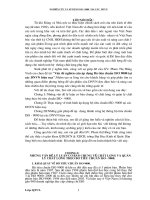
Figure 1 shows an example of a BCI test configuration.
An injection probe or set of probes capable of operating over the test frequency range is required to
interface the test equipment of the DUT. The probe shall be capable of withstanding a continuous input
power over the test frequency range regardless of the system loading.
The current measurement probe or set of probes shall be capable of operating over the test frequency range.
The current measurement probe(s) shall be terminated in the load impedance at which they are calibrated.
5.3 Test set-up
The vehicle should be tested as built; no additional grounding connections are allowed. Tests should be
performed inside a shielded room.
The distance between the vehicle and all other conductive structures, such as the walls of a shielded
room (with the exception of the ground plane underneath the vehicle) shall be a minimum of 0,5 m.
6 Test procedure
6.1 Test plan
Prior to performing the tests, a test plan shall be prepared; it shall include interface test points, mode of
operation for the DUT, acceptance criteria for the DUT, and any special instructions and changes from
the standard test. Each DUT shall be verified under the most significant conditions, i.e. at least in standby mode and in a mode where all the actuators can be excited.
6.2 Test methods
CAUTION—Hazardousvoltagesandfieldsmayexistwithinthetestarea.Careshallbetaken
to ensure that the requirements for limiting the exposure of humans to radio frequency (RF)
energy are met.
There are two test methods for the BCI test: the Substitution method and the Closed-loop method (see
5.2.1 and 5.2.2, respectively).
For both tests, the test equipment shall be connected in a manner similar to that shown in Figure 1.
--``,`,,,,,,`,,,`,``,,`,,```,`,`-`-`,,`,,`,`,,`---
2
Copyright International Organization for Standardization
Provided by IHS under license with ISO
No reproduction or networking permitted without license from IHS
© ISO 2013 – All rights reserved
Licensee=University of Alberta/5966844001, User=sharabiani, shahramfs
Not for Resale, 11/30/2013 22:18:39 MST
ISO 11451-4:2013(E)
Dimensions in millimetres
Key
1 signal generators
2 broadband amplifier
3 RF 50 Ω directional coupler
4 RF power level measuring device or equivalent
5 RF injection probe
6 RF current measurement probe (required for Closed-loop method, optional for Substitution method)
7 DUT
8 spectrum analyser or equivalent (required for Closed-loop method, optional for Substitution method)
NOTE
It is recommended that appropriate ferrite chokes be placed on the coaxial cables to the injection and
current measurement probes.
Figure1—ExampleofBCItestconfiguration
6.2.1
Substitution method
This method is based upon the use of forward power as the reference parameter for calibration and test.
In this method, the specific test level (current, voltage or power) shall be calibrated prior to the actual testing.
--``,`,,,,,,`,,,`,``,,`,,```,`,`-`-`,,`,,`,`,,`---
The test with the DUT is then conducted by subjecting it to the test signals based on the calibrated
values as predetermined in the test plan.
Measurements using this method can be affected by coupling between the injection probe and the
wiring harness as well as by reflected energy.
Mount the current injection probe around the harness (150 ± 10) mm from the connector or the outlet
aperture of the DUT being tested on the vehicle.
Where the harness contains a number of branches to a DUT, the test should be repeated with the current
probe(s) clamped around each of the branches (150 ± 10) mm from the branch termination. Under these
test conditions, the measuring probe, if used, shall be left at its previous distance from the DUT.
Using the pre-calibrated level of forward power (see Annex A), conduct a search for events over the
frequency range of the injection probe.
For each event, record the lowest forward power to the probe as the threshold of immunity even if this
is found with the injection probe in different positions at different frequencies.
A current measurement probe may optionally be mounted between the current injection probe and
the DUT. It may provide extra useful information but it may also modify the test conditions. Where
this probe is used, the measured current cannot be used to determine the performance of the DUT, but
should be retained and used during investigative work for the causes of events and the variances in test
conditions after system modifications.
© ISO 2013 – All rights reserved
Copyright International Organization for Standardization
Provided by IHS under license with ISO
No reproduction or networking permitted without license from IHS
3
Licensee=University of Alberta/5966844001, User=sharabiani, shahramfs
Not for Resale, 11/30/2013 22:18:39 MST
ISO 11451-4:2013(E)
6.2.2
Closed-loop method
The RF to the current injection probe shall be increased until
— the predetermined maximum test current level, measured using the current measurement probe,
is reached, or
— the maximum forward power (defined in the test plan) to the injection probe is achieved.
The current measurement probe shall be calibrated using the method in Annex B.
Record the threshold of susceptibility as a function of frequency.
6.3 Test report
When required in the test plan, a test report shall be submitted detailing information regarding the
test equipment, test site, systems tested, frequencies, power levels, system interactions and any other
relevant information regarding the test.
--``,`,,,,,,`,,,`,``,,`,,```,`,`-`-`,,`,,`,`,,`---
4
Copyright International Organization for Standardization
Provided by IHS under license with ISO
No reproduction or networking permitted without license from IHS
© ISO 2013 – All rights reserved
Licensee=University of Alberta/5966844001, User=sharabiani, shahramfs
Not for Resale, 11/30/2013 22:18:39 MST
ISO 11451-4:2013(E)
Annex A
(normative)
Current injection probe calibration method
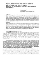
To determine the injected current flowing, the forward power measurement across a calibration
fixture is used. Figure A.1 shows an example of a test equipment configuration for the current injection
probe calibration.
Mount the current injection probe centred in the calibration fixture (see Figure A.2), and while sweeping
the test frequency range, monitor the forward power required to achieve the current at which testing is
to be conducted.
As an alternative method, once testing of the system is complete and all data has been recorded, mount
the current injection probe in the calibration fixture. At each frequency showing an event, the recorded
forward power levels are applied to the probe. The currents then observed in the calibration fixture are
those at which events within the system occurred.
Key
1 shielded enclosure
2 50 Ω coaxial load, VSWR 1,2: 1 max
3 calibration fixture
4 injection probe
5 50 Ω attenuator
6 spectrum analyser or equivalent
7 RF power level measuring device (two are required)
8 RF 50 Ω dual directional coupler (with 30 dB minimum decoupling coefficient)
9 broadband amplifier with 50 Ω output impedance
10 RF signal generator
FigureA.1—Exampleofcurrentinjectionprobecalibrationconfiguration
--``,`,,,,,,`,,,`,``,,`,,```,`,`-`-`,,`,,`,`,,`---
© ISO 2013 – All rights reserved
Copyright International Organization for Standardization
Provided by IHS under license with ISO
No reproduction or networking permitted without license from IHS
5
Licensee=University of Alberta/5966844001, User=sharabiani, shahramfs
Not for Resale, 11/30/2013 22:18:39 MST
ISO 11451-4:2013(E)
--``,`,,,,,,`,,,`,``,,`,,```,`,`-`-`,,`,,`,`,,`---
Key
1 insulation
2 removable metal cover
3 current injection probe
4 direct connection to 50 Ω measurement equipment
5 direct connection to 50 Ω load
FigureA.2—Exampleofcalibrationfixture(jig)
The physical size of the calibration fixture shall be in accordance with the probe manufacturer’s
requirements.
6
Copyright International Organization for Standardization
Provided by IHS under license with ISO
No reproduction or networking permitted without license from IHS
© ISO 2013 – All rights reserved
Licensee=University of Alberta/5966844001, User=sharabiani, shahramfs
Not for Resale, 11/30/2013 22:18:39 MST
ISO 11451-4:2013(E)
Annex B
(normative)
Current measurement probe calibration method
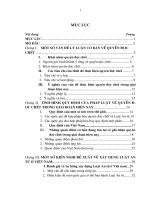
Mount the current measurement probe in the proper size calibration fixture with the probe concentric
about the centre conductor of the fixture (see Figure B.1).
Record the output of the current measurement probe as a function of frequency while maintaining a
constant RF calibration signal power.
Based on a known termination impedance, the output voltage versus input current can be determined.
Key
1 RF signal generator
2 broadband amplifier with 50 Ω output impedance
3 directional coupler with power meters
4 calibration fixture
5 current measurement probe being calibrated
6 RF termination 50 Ω
7 spectrum analyser or equivalent
FigureB.1—Exampleofcurrentmeasurementprobecalibrationconfiguration
--``,`,,,,,,`,,,`,``,,`,,```,`,`-`-`,,`,,`,`,,`---
© ISO 2013 – All rights reserved
Copyright International Organization for Standardization
Provided by IHS under license with ISO
No reproduction or networking permitted without license from IHS
7
Licensee=University of Alberta/5966844001, User=sharabiani, shahramfs
Not for Resale, 11/30/2013 22:18:39 MST
ISO 11451-4:2013(E)
Annex C
(informative)
Functionperformancestatusclassification(FPSC)
C.1 General
This annex gives examples of test severity levels which should be used in line with the principle of
functional status classification (FPSC) described in ISO 11451-1.
C.2 Classificationoftestseveritylevel
Examples of test severity levels for BCI are given in Table C.1.
Table C.1 — Example of test severity levels (BCI)
Frequency
band
MHz
1 to 3
3 to 200
200 to 400
Test Level I
mA
60 × F(MHz) / 3
60
Test Level II
mA
Test Level III
mA
100 × F(MHz) / 3
150 × F(MHz) / 3
100
150
Test Level IV
mA
200 × F(MHz) / 3
200
Test Level V
mA
60 × 200 / F(MHz) 100 × 200 / F(MHz) 150 × 200 / F(MHz) 200 × 200 / F(MHz)
C.3 Example of FPSC application using test severity levels
Specific values
agreed between
the users of
this part of
ISO 11451
Each DUT and its function(s) need to be evaluated prior to test. The category of the DUT function(s), test
severity level(s), and response criteria should then be agreed upon between the supplier and vehicle
manufacturer. This information should be documented in the test plan and used for determination of
DUT acceptance upon completion of the testing and evaluation of the test results.
--``,`,,,,,,`,,,`,``,,`,,```,`,`-`-`,,`,,`,`,,`---
An example of severity levels is given in Table C.2.
Table C.2 — Example of test severity levels (BCI)
Test severity level
Function Category 1
Function Category 2
Function Category 3
Function Category 4
L 4i
Level IV
—
—
—
Level III
Level IV
L3i
L2i
L1i
8
Copyright International Organization for Standardization
Provided by IHS under license with ISO
No reproduction or networking permitted without license from IHS
Level III
Level II
Level I
Level IV
Level III
Level II
—
Level IV
—
—
© ISO 2013 – All rights reserved
Licensee=University of Alberta/5966844001, User=sharabiani, shahramfs
Not for Resale, 11/30/2013 22:18:39 MST
--``,`,,,,,,`,,,`,``,,`,,```,`,`-`-`,,`,,`,`,,`---
Copyright International Organization for Standardization
Provided by IHS under license with ISO
No reproduction or networking permitted without license from IHS
Licensee=University of Alberta/5966844001, User=sharabiani, shahramfs
Not for Resale, 11/30/2013 22:18:39 MST
--``,`,,,,,,`,,,`,``,,`,,```,`,`-`-`,,`,,`,`,,`---
ISO 11451-4:2013(E)
ICS 33.100.20;43.040.10
Price based on 8 pages
© ISO 2013 – All rights reserved
Copyright International Organization for Standardization
Provided by IHS under license with ISO
No reproduction or networking permitted without license from IHS
Licensee=University of Alberta/5966844001, User=sharabiani, shahramfs
Not for Resale, 11/30/2013 22:18:39 MST