Tiêu chuẩn iso tr 09241 331 2012
Bạn đang xem bản rút gọn của tài liệu. Xem và tải ngay bản đầy đủ của tài liệu tại đây (4.47 MB, 90 trang )
TECHNICAL
REPORT
ISO/TR
9241-331
First edition
2012-04-01
Ergonomics of human-system
interaction —
Part 331:
Optical characteristics of
autostereoscopic displays
Ergonomie de l'interaction homme-système —
--`,,```,,,,````-`-`,,`,,`,`,,`---
Partie 331: Caractéristiques optiques des écrans autostéréoscopiques
Reference number
ISO/TR 9241-331:2012(E)
Copyright International Organization for Standardization
Provided by IHS under license with ISO
No reproduction or networking permitted without license from IHS
© ISO 2012
Not for Resale
ISO/TR 9241-331:2012(E)
--`,,```,,,,````-`-`,,`,,`,`,,`---
COPYRIGHT PROTECTED DOCUMENT
© ISO 2012
All rights reserved. Unless otherwise specified, no part of this publication may be reproduced or utilized in any form or by any means,
electronic or mechanical, including photocopying and microfilm, without permission in writing from either ISO at the address below or
ISO's member body in the country of the requester.
ISO copyright office
Case postale 56 CH-1211 Geneva 20
Tel. + 41 22 749 01 11
Fax + 41 22 749 09 47
Web www.iso.org
Published in Switzerland
ii
Copyright International Organization for Standardization
Provided by IHS under license with ISO
No reproduction or networking permitted without license from IHS
© ISO 2012 – All rights reserved
Not for Resale
ISO/TR 9241-331:2012(E)
Contents
Page
Foreword ............................................................................................................................................................ iv
Introduction ........................................................................................................................................................ vi
1
Scope ...................................................................................................................................................... 1
2
2.1
2.2
2.3
Terms and definitions ........................................................................................................................... 1
General terms ........................................................................................................................................ 1
Human factors ....................................................................................................................................... 3
Performance characteristics ................................................................................................................ 3
3
3.1
3.2
3.3
3.4
3.5
3.6
3.7
3.8
Autostereoscopic display technologies ............................................................................................. 5
General ................................................................................................................................................... 5
Cues for depth perception .................................................................................................................... 5
Stereoscopic display classification..................................................................................................... 7
Two-view (autostereoscopic) display.................................................................................................. 9
Multi-view (autostereoscopic) display .............................................................................................. 14
Integral (autostereoscopic) display ................................................................................................... 22
Discussion ........................................................................................................................................... 29
Future work .......................................................................................................................................... 36
4
4.1
4.2
4.3
4.4
4.5
Performance characteristics .............................................................................................................. 36
General ................................................................................................................................................. 36
Crosstalk .............................................................................................................................................. 38
Visual artefacts .................................................................................................................................... 42
3D fidelity ............................................................................................................................................. 45
Future work .......................................................................................................................................... 46
5
5.1
5.2
5.3
5.4
Optical measurement methods .......................................................................................................... 46
General ................................................................................................................................................. 46
Measurement conditions .................................................................................................................... 47
Measurement methods ....................................................................................................................... 52
Future work .......................................................................................................................................... 68
6
6.1
6.2
6.3
6.4
6.5
Viewing spaces and their analysis .................................................................................................... 68
General ................................................................................................................................................. 68
Qualified viewing spaces .................................................................................................................... 69
Related performance characteristics ................................................................................................ 73
Analysis methods ................................................................................................................................ 75
Future work .......................................................................................................................................... 77
7
Further work ......................................................................................................................................... 78
Annex A (informative) Overview of the ISO 9241 series ............................................................................... 79
Annex B (informative) Head tracking technology .......................................................................................... 80
Bibliography ...................................................................................................................................................... 81
© ISO for
2012
– All rights reserved
Copyright International Organization
Standardization
Provided by IHS under license with ISO
No reproduction or networking permitted without license from IHS
--`,,```,,,,````-`-`,,`,,`,`,,`---
Not for Resale
iii
ISO/TR 9241-331:2012(E)
Foreword
ISO (the International Organization for Standardization) is a worldwide federation of national standards bodies
(ISO member bodies). The work of preparing International Standards is normally carried out through ISO
technical committees. Each member body interested in a subject for which a technical committee has been
established has the right to be represented on that committee. International organizations, governmental and
non-governmental, in liaison with ISO, also take part in the work. ISO collaborates closely with the
International Electrotechnical Commission (IEC) on all matters of electrotechnical standardization.
International Standards are drafted in accordance with the rules given in the ISO/IEC Directives, Part 2.
The main task of technical committees is to prepare International Standards. Draft International Standards
adopted by the technical committees are circulated to the member bodies for voting. Publication as an
International Standard requires approval by at least 75 % of the member bodies casting a vote.
In exceptional circumstances, when a technical committee has collected data of a different kind from that
which is normally published as an International Standard (“state of the art”, for example), it may decide by a
simple majority vote of its participating members to publish a Technical Report. A Technical Report is entirely
informative in nature and does not have to be reviewed until the data it provides are considered to be no
longer valid or useful.
Attention is drawn to the possibility that some of the elements of this document may be the subject of patent
rights. ISO shall not be held responsible for identifying any or all such patent rights.
ISO/TR 9241-331 was prepared by Technical Committee ISO/TC 159, Ergonomics, Subcommittee SC 4,
Ergonomics of human-system interaction.
ISO 9241 consists of the following parts, under the general title Ergonomic requirements for office work with
visual display terminals (VDTs):
Part 1: General introduction
Part 2: Guidance on task requirements
Part 4: Keyboard requirements
Part 5: Workstation layout and postural requirements
Part 6: Guidance on the work environment
Part 9: Requirements for non-keyboard input devices
Part 11: Guidance on usability
Part 12: Presentation of information
Part 13: User guidance
Part 14: Menu dialogues
Part 15: Command dialogues
Part 16: Direct manipulation dialogues
--`,,```,,,,````-`-`,,`,,`,`,,`---
iv
Copyright International Organization for Standardization
Provided by IHS under license with ISO
No reproduction or networking permitted without license from IHS
© ISO 2012 – All rights reserved
Not for Resale
ISO/TR 9241-331:2012(E)
ISO 9241 also consists of the following parts, under the general title Ergonomics of human-system interaction:
Part 20: Accessibility guidelines for information/communication technology (ICT) equipment and services
Part 100: Introduction to standards related to software ergonomics [Technical Report]
Part 110: Dialogue principles
Part 129: Guidance on software individualization
Part 143: Forms
Part 151: Guidance on World Wide Web user interfaces
Part 154: Interactive voice response (IVR) applications
Part 171: Guidance on software accessibility
Part 210: Human-centred design for interactive systems
Part 300: Introduction to electronic visual display requirements
Part 302: Terminology for electronic visual displays
Part 303: Requirements for electronic visual displays
Part 304: User performance test methods for electronic visual displays
Part 305: Optical laboratory test methods for electronic visual displays
Part 306: Field assessment methods for electronic visual displays
Part 307: Analysis and compliance test methods for electronic visual displays
Part 308: Surface-conduction electron-emitter displays (SED) [Technical Report]
Part 309: Organic light-emitting diode (OLED) displays [Technical Report]
Part 310: Visibility, aesthetics and ergonomics of pixel defects [Technical Report]
Part 331: Optical characteristics of autostereoscopic displays [Technical Report]
Part 400: Principles and requirements for physical input devices
Part 410: Design criteria for physical input devices
Part 411: Evaluation methods for the design of physical input devices [Technical Specification]
Part 420: Selection of physical input devices
Part 910: Framework for tactile and haptic interaction
Part 920: Guidance on tactile and haptic interactions
--`,,```,,,,````-`-`,,`,,`,`,,`---
User-interface elements, requirements, analysis and compliance test methods for the reduction of
photosensitive seizures, ergonomic requirements for the reduction of visual fatigue from stereoscopic images,
and the evaluation of tactile and haptic interactions are to form the subjects of future Parts 161, 391, 392 and
940.
© ISO for
2012
– All rights reserved
Copyright International Organization
Standardization
Provided by IHS under license with ISO
No reproduction or networking permitted without license from IHS
v
Not for Resale
ISO/TR 9241-331:2012(E)
Introduction
Recent developments in display technologies have made it possible to render highly realistic content on
high-resolution colour displays. The developments include advanced 3D display technologies such as
autostereoscopic displays. The new 3D displays extend the capabilities of applications by giving the user
more-realistic-than-ever perception in various application fields. This is valid not only in the field of leisure but
also in the fields of business and education, and in medical applications.
Nevertheless, 3D displays have display-specific characteristics originating from the basic principles of the
image formation applied for the different 3D display designs. Among negative characteristics are imperfections
that affect the visual quality of the displayed content and the visual experience of the users. These
imperfections can induce visual fatigue for the users, which is one of the image safety issues described in
IWA 3:2005. Nevertheless, it is important for the end user to be able to enjoy of the benefits of the 3D display
without suffering any undesirable biomedical effects. It is therefore necessary that a standardized
methodology be established which characterizes and validates technologies in order to ensure the visual
quality of the displays and the rendered content. The development of such a methodology has to be based on
the human perception and performance in the context of stereoscopic viewing.
The negative characteristics, by nature, originate from both 3D displays and 3D image content. In this part of
ISO 9241, however, attention is focussed only on 3D display, for simplicity of discussion and as a first step.
In ISO 9241-303, performance objectives are described for virtual head-mounted displays (HMDs). This is
closely related to autostereoscopic displays, but not directly applicable to them.
Considering the growing use of autostereoscopic displays, and the need for a methodology for their
characterization in order to reduce visual fatigue caused by them, this Technical Report presents basic
principles for related technologies, as well as optical measurement methods required for the characterization
of the current technologies and for a future International Standard on the subject.
Since this Technical Report deals with display technologies that are in continual development, its content will
be updated if and as necessary. It includes no content intended for regulatory use.
--`,,```,,,,````-`-`,,`,,`,`,,`---
vi
Copyright International Organization for Standardization
Provided by IHS under license with ISO
No reproduction or networking permitted without license from IHS
© ISO 2012 – All rights reserved
Not for Resale
TECHNICAL REPORT
ISO/TR 9241-331:2012(E)
Ergonomics of human-system interaction —
Part 331:
Optical characteristics of autostereoscopic displays
1
Scope
This part of ISO 9241 establishes an ergonomic point of view for the optical properties of autostereoscopic
displays (ASDs), with the aim of reducing visual fatigue caused by stereoscopic images on those displays. It
gives terminology, performance characteristics and optical measurement methods for ASDs.
It is applicable to spatially interlaced autostereoscopic displays (two-view, multi-view and integral displays) of
the transmissive and emissive types. These can be implemented by flat-panel displays, projection displays,
etc.
2
Terms and definitions
For the purposes of this document, the following terms and definitions apply.
2.1
General terms
2.1.1
3D display
display device or system including a special functionality for enabling depth perception
2.1.2
stereoscopic display
3D display where depth perception is induced by binocular parallax
--`,,```,,,,````-`-`,,`,,`,`,,`---
NOTE 1
People perceive depth from the retinal disparity provided by binocular parallax.
NOTE 2
Stereoscopic displays
autostereoscopic displays.
NOTE 3
include
stereoscopic
displays
requiring
glasses,
stereoscopic
HMDs
and
See ISO 9241-302:2008, 3.5.5, binocular display device.
2.1.3
autostereoscopic display
ASD
stereoscopic display that requires neither viewing aids such as special glasses nor head-mounted apparatus
NOTE
Autostereoscopic displays includes two-view displays, multi-view displays and integral displays, as well as
other types of display not discussed in this part of ISO 9241, such as holographic displays and volumetric displays.
2.1.4
two-view display
two-view autostereoscopic display
autostereoscopic display that creates two monocular views with which the left and right stereoscopic images
are coupled
© ISO for
2012
– All rights reserved
Copyright International Organization
Standardization
Provided by IHS under license with ISO
No reproduction or networking permitted without license from IHS
1
Not for Resale
ISO/TR 9241-331:2012(E)
2.1.5
multi-view display
multi-view autostereoscopic display
autostereoscopic display that creates more than two monocular views with which the stereoscopic images are
coupled
NOTE 1
It becomes an autostereoscopic display when the number of stereoscopic images is increased from two to
more than two.
NOTE 2
Principally, one of multiple stereoscopic images corresponds to one of multiple stereoscopic views, yet not
necessarily excluding one-to-multi correspondence.
2.1.6
integral display
integral autostereoscopic display
autostereoscopic display that is intended to optically reproduce three-dimensional objects in space
NOTE
Since, at present, it is not easy to make the optical reproduction perfect, integral displays are not necessarily
free from such factors of undesirable biomedical effect as accommodation-vergence inconsistency (see 3.7, 4.1).
NOTE
--`,,```,,,,````-`-`,,`,,`,`,,`---
2.1.7
stereoscopic images
set of images with parallax shown on a stereoscopic display
See 2.1.8.
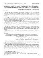
2.1.8
stereoscopic views
pair of sights provided by a stereoscopic display, which induce stereopsis
NOTE
See Figure 1.
Key
1
2
autostereoscopic display
stereoscopic images
3
4
stereoscopic views
monocular view (left eye)
5
monocular view (right eye)
Figure 1 — Relation between stereoscopic images, stereoscopic views and monocular view
2
Copyright International Organization for Standardization
Provided by IHS under license with ISO
No reproduction or networking permitted without license from IHS
© ISO 2012 – All rights reserved
Not for Resale
ISO/TR 9241-331:2012(E)
2.1.9
monocular view
one stereoscopic view
NOTE
See 2.1.8.
2.1.10
number of views
number of monocular views with which stereoscopic images are coupled
2.2
Human factors
NOTE 1
See IWA 3:2005, 2.15.
NOTE 2
Binocular parallax is equivalent to the optic angle between the visual axes of both eyes, when they are fixated
to a single point.
2.2.2
visual fatigue
eyestrain or asthenopia, which shows a wide range of visual symptoms, including tiredness, headache and
soreness of the eyes, caused by watching images in a visual display
NOTE 1
Adapted from IWA 3:2005, 2.13.
NOTE 2
See also ISO 9241-302:2008, 3.5.3.
2.2.3
accommodation
adjustment of the optics of an eye to keep an object in focus on the retina as its distance from the eye varies
[SOURCE: ISO 9241-302:2008, 3.5.1, modified — the Note to the definition has not been included.]
NOTE
Adapted from IWA 3:2005, 2.18.
2.2.4
convergence
turning inward of the lines of sight toward each other as the object of fixation moves toward the observer
[SOURCE: ISO 9241-302:2008, 3.5.10]
NOTE
2.3
See also IWA 3:2005, 2.19.
Performance characteristics
2.3.1
3D crosstalk
leakage of an unwanted image data to each eye
2.3.2
interocular crosstalk
leakage of the stereoscopic image(s) from one eye to the other
© ISO for
2012
– All rights reserved
Copyright International Organization
Standardization
Provided by IHS under license with ISO
No reproduction or networking permitted without license from IHS
3
Not for Resale
--`,,```,,,,````-`-`,,`,,`,`,,`---
2.2.1
binocular parallax
apparent difference in the direction of a point as seen separately by one eye and by the other, while the head
remains in a fixed position
ISO/TR 9241-331:2012(E)
2.3.3
interocular luminance difference
difference in luminance between stereoscopic views
2.3.4
interocular chromaticity difference
difference in chromaticity between stereoscopic views
2.3.5
interocular contrast difference
difference in contrast between stereoscopic views
2.3.6
3D moiré
periodical irregularity of luminance or chromaticity in space or angular directions on a 3D display
2.3.7
pseudoscopic images
pseudo-stereoscopic images
set of images with inverted parallax shown on a stereoscopic display
2.3.8
3D image resolution
spatial resolution of the image with depth shown on a stereoscopic display
NOTE
The term “spatial resolution” refers to horizontal and vertical resolution, as shown in the ISO 9241 300 series.
--`,,```,,,,````-`-`,,`,,`,`,,`---
2.3.9
qualified viewing space
QVS
autostereoscopic displays space for the eye in which image(s) is observed at an acceptable level of visual
fatigue
NOTE 1
See also ISO 9241-302, 3.5.42.
NOTE 2
QVS is defined separately for each eye as the measurement result is unambiguous and equally valid for all
observers, whereas the measured QBVS and QSVS results as such are only valid for people with average eye separation.
NOTE 3
This term still needs discussion, because “monocular” viewing space is insufficient for determining the
characteristics of autostereoscopic displays that require “binocular” viewing.
2.3.10
qualified binocular viewing space
QBVS
space in which images on a stereoscopic display are observed by both eyes at an acceptable level of visual
fatigue
NOTE 1
This term is based on the concept that there should be space where visual fatigue caused by pseudostereoscopy is small enough.
NOTE 2
This term still needs discussion, because it is not clear whether there can exist a space larger than QSVS,
which would still satisfy the visual fatigue requirements.
2.3.11
qualified stereoscopic viewing space
QSVS
space in which images on a stereoscopic display induce stereopsis at an acceptable level of visual fatigue
NOTE
This term is based on the concept that there should be space where visual fatigue caused by stereoscopic
images is small enough.
4
Copyright International Organization for Standardization
Provided by IHS under license with ISO
No reproduction or networking permitted without license from IHS
© ISO 2012 – All rights reserved
Not for Resale
ISO/TR 9241-331:2012(E)
3.1
Autostereoscopic display technologies
General
In this clause, technological features of autostereoscopic displays are described. Firstly, information for people
to perceive depth provided by autostereoscopic displays is explained. This is essential for understanding the
basics of autostereoscopic display technologies. Secondly, the autostereoscopic displays are classified
according to their technological aspects. Three different display technologies are presented based on their
principles, structures and features. Finally, to establish optical measurement methods for evaluating visual
fatigue caused by these autostereoscopic displays, the related matters are discussed in the light of both,
ergonomics and technologies.
3.2
Cues for depth perception
People usually perceive the three-dimensional visual world based on retinal images of two eyes. The cues for
such depth perception are not only binocular cues but also monocular cues. These cues are shown in Table 1.
Table 1 — Classification of depth cues
Absolute depth
Binocular
Monocular
Convergence/Binocular parallax
Accommodation
Motion parallax
Relative depth
Binocular disparity
Motion disparity
Pictorial depth cues a
a
Pictorial depth cues
Geometrical perspective
Relative/familiar size
Shading/Shadow
Occlusion
Texture
Aerial perspective, etc.
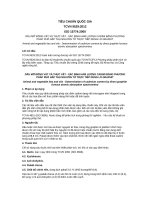
For autostereoscopic displays, the device itself provides binocular and monocular parallax as absolute
distance cues, and binocular and monocular disparity as relative depth cues. Binocular parallax is presented
as interocular differences in apparent direction of a target, while binocular disparity is presented as in relative
position of retinal images of two different objects. Both concepts are shown in Figure 2.
© ISO for
2012
– All rights reserved
Copyright International Organization
Standardization
Provided by IHS under license with ISO
No reproduction or networking permitted without license from IHS
5
Not for Resale
--`,,```,,,,````-`-`,,`,,`,`,,`---
3
ISO/TR 9241-331:2012(E)
Key
1
Vieth Muller circle
5
image for left eye
O
fixated object
2
binocular parallax LOR
6
right eye
L
left eye image
3
display surface
7
left eye
R
right eye image
4
image for right eye
B
target object
d BR d BL binocular disparity
Figure 2 — Binocular parallax and disparity
If an object, (e.g. object “O” in Figure 2a), is fixated by the two eyes, the apparent direction of the object
relative to the right eye is different from the direction relative to the left eye. This difference is called binocular
parallax. Moreover in Figure 2a, when the other object, such as “B”, exist, the apparent gap between the two
objects “O” and “B” is different in the views of the left and the right eye (see Figure 2b). This difference
originates in binocular parallax. This difference, binocular disparity, is described as the difference in angle
between d BL and d BR as shown in Figure 2.
In Figure 2, the circle connecting three points, two nodes of the eyes and the fixation point “O”, is the ViethMüller circle, which is the theoretical horopter. Any point on the horopter builds up its retinal image on
corresponding points of the two retinae, thus are viewed single. Therefore, none of the points on the circle
produce binocular disparity with each other including the fixated point “O”. The actual horopter, or empirical
horopter, has been measured, and is known as slightly different in its shape from the theoretical horopter.
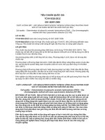
Motion parallax and disparity are caused when different images are observed from different positions. As the
head moves from left to right, the absolute and relative positions of object images change, which creates
motion parallax and disparity, respectively, as shown in Figure 3.
--`,,```,,,,````-`-`,,`,,`,`,,`---
6
Copyright International
Organization for Standardization
Provided by IHS under license with ISO
No reproduction or networking permitted without license from IHS
© ISO 2012 – All rights reserved
Not for Resale
ISO/TR 9241-331:2012(E)
1
motion parallax M 12
4
right eye position at time T1
B
target object
2
image position at time T1
5
right eye position at time T2
O
fixated object
3
image position at time T2
6
head movement
d M 1 d M 2 motion disparity
Figure 3 — Motion parallax and disparity
--`,,```,,,,````-`-`,,`,,`,`,,`---
Key
When an object (e.g. object “O” in Figure 3) is fixated by a single eye during head movements, the apparent
direction of the object relative to the eye varies depending on the eye’s position. This variation of apparent
direction is called motion parallax. Moreover, when the two objects, “O” and “B” in Figure 3, are seen during
head movements, the apparent adjacency changes, for example, between the views at time T1 and time T2
(see Figure 3). This change is produced because of motion parallax. This difference is described as the
difference in angle between d M 1 and d M 2 , or motion disparity.
The term “motion parallax” is used for motion disparity. For example, motion parallax is defined as the relative
movement of images across the retina resulting from movement of the observer.
3.3
Stereoscopic display classification
A stereoscopic display is defined as a 3D display, for which depth perception is induced by binocular parallax.
The binocular parallax provides disparity between retinal images, which induces stereopsis.
Stereoscopic displays can be classified into three types:
autostereoscopic displays;
stereoscopic Head-Mounted Displays (HMDs); and
stereoscopic displays requiring glasses.
Stereoscopic viewing has traditionally required users to wear special viewing devices, like glasses with
polarizing or colour filters. In contrast, autostereoscopic displays do not require special viewing devices.
Whether glasses are required or not is an important factor in ergonomics. The visual factors of HMDs are also
different from those of autostereoscopic displays or stereoscopic displays using glasses. This is the reason
© ISO for
2012
– All rights reserved
Copyright International Organization
Standardization
Provided by IHS under license with ISO
No reproduction or networking permitted without license from IHS
7
Not for Resale
ISO/TR 9241-331:2012(E)
why these three display types are classified in three separate categories. In this part of ISO 9241, only
autostereoscopic displays are covered.
Until now, many types of autostereoscopic displays have been developed and various concepts of
classification have been proposed according to their related factors. Figure 4 shows the classification of
autostereoscopic displays in this part of ISO 9241. In this taxonomy, ergonomics aspects of autostereoscopic
display hardware are the basis for the classification. There exist other stereoscopic display technologies, that
are not shown in this taxonomy – some of which are not yet even known.
Figure 4 — Taxonomy of stereoscopic displays
Autostereoscopic displays can be classified into two-view, multi-view and integral displays according to the
viewpoints of visual ergonomics. In this classification, the integral display belongs to autostereoscopic displays,
as it fulfils the definition of autostereoscopic displays.
Autostereoscopic displays could also be classified into spatially and temporally interlaced types. Human
factors for the spatially interlaced type are generally different from those for the temporally interlaced type.
Compared to the spatially interlaced type, the temporally interlaced type can have discriminative
characteristics, such as temporal changes in luminance and colour, and flicker, which can affect the visual
quality of the displayed content and the visual experience of the users.
An autostereoscopic display is able to produce, at least, two different images which are perceived by the two
eyes of the user, respectively. Those images are used for producing binocular parallax and disparity to
simulate depth among the observer and objects. Examples of producing different images are shown in
Figure 2 and Figure 3.
For the multi-view and integral displays, lateral head movements parallel to display surface can derive parallax
images, which simulate motion parallax and disparity also for simulating depth among observer and objects.
Autostereoscopic displays have some principle differences in their optical characteristics compared to
conventional two-dimensional (2D) displays:
Binocular difference;
An autostereoscopic display is able to show a different image for each eye, while a 2D display is not.
Directional non-uniformity;
An autostereoscopic display provides different images in different angular directions, and thus,
angular directional characteristics are not made to be uniform. For a 2D display, angular uniformity is
tried to be maintained.
In some cases, in order to improve some of the characteristics, all spatial screen locations are not
made to have the same characteristics.
8
Copyright International Organization for Standardization
Provided by IHS under license with ISO
No reproduction or networking permitted without license from IHS
© ISO 2012 – All rights reserved
Not for Resale
--`,,```,,,,````-`-`,,`,,`,`,,`---
Lateral non-uniformity.
ISO/TR 9241-331:2012(E)
Some of the autostereoscopic displays can provide not only horizontal but also vertical parallax/disparity. In
this part of ISO 9241, mainly one-dimensional parallax in the horizontal direction is discussed.
A typical spatially interlaced autostereoscopic display consists of a base 2D display panel and some additional
(electro-)optical components for controlling the light output angles, such as parallax barrier or lenticular sheet.
In spatially interlaced displays, the displayed picture elements, pixels or sub-pixels, are multiplexed into two or
more sections with slightly different stereoscopic views of the displayed content. The parallax barrier or
lenticular structure conveys the information to the space in front of the display. A parallax barrier has an array
of light blocking opaque barriers, each slit between the barriers corresponding to each certain pixel group. In
lenticular type autostereoscopic displays, semi-cylindrical lenses are used instead of the slits to lessen the
absorption of display illumination. In addition, many other possibilities exist for the creation of a two-view
spatially interlaced display. When the two eyes of the user receive the binocular parallax resulting from these
arrangements, depth perception is induced. The basic principle of the parallax barrier type autostereoscopic
display is illustrated in Figure 5. In this figure, the arrow represents the main direction of light from each pixel.
For simplicity, descriptions and drawing of autostereoscopic displays henceforth refer to the parallax barrier
type autostereoscopic display.
Key
1
display (sub)pixels
3
light rays from pixels for the left eye
2
parallax barrier
4
light rays from pixels for the right eye
Figure 5 — Conceptual illustration of basic display technology in a two-view display
Parallax barrier or lenticular array structures are necessary to be aligned with the display pixels. Content of
the display pixels or sub-pixels should be interlaced according to these structures. Vertical structures typically
result in reduced observed resolution in horizontal direction. Slanted or step barrier structures can divide the
resolution drop both in horizontal and vertical direction.
An autostereoscopic display can generally be used as a 2D display by showing images without binocular
parallax. Some autostereoscopic displays have a 2D/3D selection switch by which they are turned to 2D mode,
if needed.
3.4
3.4.1
Two-view (autostereoscopic) display
Definition and principle
A two-view display is defined as an autostereoscopic display, that creates two monocular views with which the
left and right stereoscopic images are coupled. On a two-view display, left and right images are shown. The
left part of stereoscopic images is observed by the left eye, while the right part is observed by the right eye, as
illustrated in Figure 6. As a result, binocular parallax for depth perception can be created.
--`,,```,,,,````-`-`,,
© ISO for
2012
– All rights reserved
Copyright International Organization
Standardization
Provided by IHS under license with ISO
No reproduction or networking permitted without license from IHS
9
Not for Resale
ISO/TR 9241-331:2012(E)
Key
two-view display
4
right image
7
2
stereoscopic images
5
stereoscopic views
3
left image
6
monocular view (left eye)
monocular view (right eye)
Figure 6 — Basic working principle of a two-view display
3.4.2
Structure and optical property
This subclause describes the optical properties of two-view displays, while different types of qualified viewing
spaces for the display are described in clause 6 based on the optical properties and performance
characteristics described in Clause 4.
In a two-view display, the display panel has two kinds of pixel or sub-pixel groups for showing left and right
images (left-eye pixels and right-eye pixels), as shown in Figure 7. On the display panel, an optical component
for distributing the light from each pixel group, such as a parallax barrier, is attached. Each slit of the parallax
barrier corresponds to each pixel set of left- and right-eye pixels. The light from each pixel set and the light
from its adjacent pixel set passing through the corresponding slit will generate main and side lobes,
respectively. The lobe can be defined as a segment formed by a set of light rays that are emitted from the
screen for producing stereoscopic images. On the boundary of lobe, the luminance of the right set is the same
as that of the left set.
10
Copyright International Organization for Standardization
Provided by IHS under license with ISO
No reproduction or networking permitted without license from IHS
© ISO 2012 – All rights reserved
Not for Resale
--`,,```,,,,````-`-`,,`,,`,`,,`---
1
ISO/TR 9241-331:2012(E)
Key
1
two-view display
4
parallax barrier
7
boundary of lobe
2
left eye pixel
5
light for main lobe
8
angle
3
right eye pixel
6
light for side lobe
9
luminance
Figure 7 — Angular luminance output of a two-view (parallax barrier) display
For widening each lobe, generally the angular distributions on each display location are made to be different.
This is illustrated in Figure 8, as well as the generation of lobes. The recurring lobes can be applicable to
simultaneous multi-user viewing.
--`,,```,,,,````-`-`,,`,,`,`,,`---
© ISO for
2012
– All rights reserved
Copyright International Organization
Standardization
Provided by IHS under license with ISO
No reproduction or networking permitted without license from IHS
11
Not for Resale
ISO/TR 9241-331:2012(E)
--`,,```,,,,````-`-`,,`,,`,`,,`---
Key
1 left location
2 centre location
3
4
right location
main lobe
5
side lobe
Figure 8 — Varying angular light distributions in different screen locations and the generation of
main lobe and side lobes
As shown in Figure 9, when pixels of only one of the two stereoscopic images are on (=white), light all over
the screen area from these pixels concentrates into the space. In this space, each part of stereoscopic images
can be seen. This important space or position is sometimes called a “viewpoint”.
Key
6 space, where the light from left-eye pixels concentrates
Figure 9 — Concentration of light from left-eye and right-eye pixels
12
Copyright International Organization for Standardization
Provided by IHS under license with ISO
No reproduction or networking permitted without license from IHS
© ISO 2012 – All rights reserved
Not for Resale
ISO/TR 9241-331:2012(E)
--`,,```,,,,````-`-`,,`,,`,`,,`---
When both eyes are placed inside the same lobe space, pseudoscopy does not occur. For example, at
position (A) in Figure 10, the observer can see stereoscopic images on the whole screen. At position (B),
stereoscopic images can be seen in the centre of the screen, while left and right next to it, 2D images are
seen. At position (C) partially outside the lobe, the observer perceives pseudoscopy on the left side of the
screen.
Key
1 main lobe
5 superimposed images of left and
right eyes
9 left and right eye/left
eye/pseudoscopy
2
side lobe
6
left eye/left and right eye
L
left image
3
left-eye view
7
left and right eye/right eye
R
right image
4
right-eye view
8
right eye/left eye/pseudoscopy
3D stereopsis
Figure 10 — Relation between observer’s position and the observed view
Figure 11 shows some display interlacing method examples for two-view displays. The light-directing optical
component is aligned with the pixels typically in vertical direction, but other solutions are possible, as well.
Both vertical and slanted structures mainly create parallax in the horizontal direction.
© ISO for
2012
– All rights reserved
Copyright International Organization
Standardization
Provided by IHS under license with ISO
No reproduction or networking permitted without license from IHS
13
Not for Resale
ISO/TR 9241-331:2012(E)
a) Pixel interlacing with
horizontal
sub-pixel
arrays
b) Pixel interlacing with
vertical
sub-pixel
arrays
c) Sub-pixel interlacing
with horizontal subpixel arrays
d) Slanted or step
interlacing
with
horizontal sub-pixels
Figure 11 — Different pixel interlacing example illustrations assuming square (R,G,B) pixels in twoview displays
Optionally, a combination of relative head position tracking and mechanically, electrically or optically
adjustable display components can be used in order to change the location and/or shape of the lobes to
match with the user position.
NOTE
3.4.3
A general description of tracking technology is comprised in Annex B.
Features
A two-view display satisfies the minimum requirements for being classified as autostereoscopic display. It is a
comparatively simple stereoscopic method and the preparation and obtaining of contents is fairly easy.
Furthermore, high resolution results in clear 3D views and large stereo effect. As a drawback, the display
technology itself does not support simulation of motion parallax and the viewing space is rather small.
3.5
3.5.1
Multi-view (autostereoscopic) display
Definition and principle
A multi-view display is defined as an autostereoscopic display that creates more than two monocular views
with which the stereoscopic images are coupled. Figure 12 shows a typical multi-view display, whose number
of views is four. The number of views is defined as the number of monocular views, with which stereoscopic
images are coupled. On the multi-view display, four stereoscopic images (image 1, 2, 3 and 4), are shown.
When the left eye sees image 1 and the right eye sees image 2, binocular parallax for depth perception can
be created. In addition, when each eye sees the other images, binocular parallax can also be created. This
means that motion parallax can be obtained, when the head moves from left to right and vice versa.
14
Copyright International Organization for Standardization
Provided by IHS under license with ISO
No reproduction or networking permitted without license from IHS
--`,,```,,,,````-`-`,,`,,`,`,,`---
© ISO 2012 – All rights reserved
Not for Resale
--`,,```,,,,````-`-`,,`,,`,`,,`---
ISO/TR 9241-331:2012(E)
Key
1
multi-view display
5
image 3
9
monocular view (right eye)
2
stereoscopic images
6
image 4
10 head movement
3
image 1
7
stereoscopic views
11 motion parallax
4
image 2
8
monocular view (left eye)
Figure 12 — Principle of multi-view display
3.5.2
Structure and optical property
This subclause describes the optical properties of multi-view displays, while different types of qualified viewing
spaces for the display are described in Clause 6, based on the optical properties and performance
characteristics described in Clause 4.
In a multi-view display, the display panel is equipped with more than two kinds of pixel groups for showing
stereoscopic images. Similar to two-view displays, a sheet of parallax barrier or lenticular lens is generally
© ISO for
2012
– All rights reserved
Copyright International Organization
Standardization
Provided by IHS under license with ISO
No reproduction or networking permitted without license from IHS
15
Not for Resale
ISO/TR 9241-331:2012(E)
used for distributing the light from each pixel group. For example, in the parallax barrier type as shown in
Figure 13, each slit of parallax barrier corresponds to each set of pixels (pixels for images 1, 2, 3 and 4). The
light from each pixel set going through the corresponding slit forms the main lobe, while the light going through
the adjacent slit forms the side lobe.
--`,,```,,,,````-`-`,,`,,`,`,,`---
Key
1
multi-view display
5
pixel for image 4
9
boundary of lobe
2
pixel for image 1
6
parallax barrier
10 angle
3
pixel for image 2
7
light for main lobe
11 luminance
4
pixel for image 3
8
light for side lobe
Figure 13 — Structure of a multi-view display
Due to the nature of lobe shape as shown in Figure 14, the angular distribution of light generally varies
depending on each screen location, similar to two-view displays.
16
Copyright International Organization for Standardization
Provided by IHS under license with ISO
No reproduction or networking permitted without license from IHS
© ISO 2012 – All rights reserved
Not for Resale
ISO/TR 9241-331:2012(E)
Key
1
left location
3
right location
2
centre location
4
main lobe
5
side lobe
Figure 14 — Formation of main lobe and side lobe
--`,,```,,,,````-`-`,,`,,`,`,,`---
As shown in Figure 15, when only one pixel group is on, light all over the screen originating from the pixel
group concentrates towards one point in space. For example, at position (a), which is inside the space, when
only one pixel group of image 1 is white, the entire screen will be white. At positions (b), (c) and (d), only a
part of screen will be white. There, one of the stereoscopic images can be seen on the entire screen. The
spaces around these positions feature a multi-view display. This space or position is sometimes called a
“viewpoint”.
Key
1
space where the light from pixels for image 1 concentrates
Figure 15 — Concentration of light from pixels for image 1
© ISO for
2012
– All rights reserved
Copyright International Organization
Standardization
Provided by IHS under license with ISO
No reproduction or networking permitted without license from IHS
17
Not for Resale
ISO/TR 9241-331:2012(E)
Key
1
main lobe
4
right-eye view
Im2 image 2
3D stereopsis
2
side lobe
5
superimposed images of left and right eyes
Im3 image 3
P
3
left-eye view
Im1 image 1
pseudoscopy
Im4 image 4
3D* In case of B, although each eye sees overlapped image, stereopsis can be induced because both eyes see the different images.
Overlapped image will cause blur, but it depends on the simulated depth (see 3.7.1).
Figure 16 — Relation between observer’s position and the observed views
18
Copyright International Organization for Standardization
Provided by IHS under license with ISO
No reproduction or networking permitted without license from IHS
--`,,```,,,,````-`-`,,`,,`,`,,`---
© ISO 2012 – All rights reserved
Not for Resale
ISO/TR 9241-331:2012(E)
The structure of the multi-view display is similar to that of the two-view display. However, optical properties are
quite different between the two display types. When each eye (pupil) is correctly placed inside the diamond
shaped viewing spaces, as shown in Figure 16 position (A), the left eye sees one part of the stereoscopic
images, and the right eye sees another part. As a result, binocular parallax for depth perception is created.
At position (B) in Figure 16, each of the eyes sees a double or blurred image. For example, the left eye sees
image 1 and image 2, and right eye sees image 3 and image 4. In this situation, one monocular view
corresponds to two stereoscopic images. Although each eye sees an overlapped image, stereopsis can be
induced because both eyes see different images. Overlapping can cause a double image, but it depends on
the amount of simulated depth. When the depth is small, neither the double image nor the blurred image will
be apparent. This is also related to the number of views per interpupillary distance (IPD).
EXAMPLE
Larger number of views per IPD will decrease the parallax on adjacent stereoscopic images (see 3.7.1).
In addition, in a two-view display, when both eyes see double images, stereopsis can not be induced, because
the double image contains pseudoscopic images. However, in a multi-view display, since the double images
do not always contain pseudoscopic images, stereopsis can be achieved. Therefore, the effect of
pseudoscopic images should be carefully considered.
At position (C) in Figure 16, stereopsis can be created, although each of stereoscopic views consists of three
stereoscopic images.
At position (D), stereopsis can not be achieved.
At position (E), pseudoscopy is observed all over the screen.
At position (F), pseudoscopy is observed on a part of the screen.
The luminance angular profile is also related to the screen view. As shown in Figure 17, the larger the
overlapping of the profile, the wider is the region of double image and the smaller is the luminance fluctuation.
Figure 18 shows a multi-view display, whose number of views is eight. Compared to the multi-view display in
Figure 16 (whose number of views is four), the multi-view display in Figure 18 has smaller angular-pitch of
light from each pixel. At position (A), the left eye sees image 1 and the right eye sees image 3, so that
binocular parallax is created. At position (B), although the viewing distance is larger than that of position (D) in
Figure 16, stereopsis can still be induced.
Pixel assignment in a multi-view display is an important issue, because the number of pixel groups required
for showing stereoscopic images is large. Figure 19 illustrates an example of a pixel assignment in a multiview display. In Figure 19 (b), sub-pixels of the same colour are arranged vertically. In this case, same
number of sub-pixels are arranged vertically, since the parallax barrier with vertical slits is used as shown in
Figure 19 (a). As a result, as shown in Figure 19 (c), the horizontal resolution becomes 1/4, yet the vertical
resolution is unchanged. This decreases the image quality and can be a source of visual fatigue. The situation
is worsened by a further increase of number of views.
--`,,```,,,,````-`-`,,`,,`,`,,`---
In response to this issue, some technologies, such as step barrier technology, slanted barrier technology and
slanted lenticular technology, have been proposed. In the step barrier technology, the parallax barrier has tiny
rectangular holes arranged in a slanted line like stairs, as shown in Figure 20 (a). RGB sub-pixels on the
slanted line can be treated as one pixel, as shown in Figure 20 (c). As a result, the horizontal resolution will
be 1/3, and the vertical resolution will be 3/4. This means that the step barrier technology can lessen the
resolution issue, as the decrease of resolution in horizontal can be reduced. In general, the aspect ratio of
each pixel is 9 to n, whereas n is the number of views. In theory, vertical parallax can be introduced to multiview displays.
© ISO for
2012
– All rights reserved
Copyright International Organization
Standardization
Provided by IHS under license with ISO
No reproduction or networking permitted without license from IHS
19
Not for Resale