Tiêu chuẩn iso 06363 6 2012
Bạn đang xem bản rút gọn của tài liệu. Xem và tải ngay bản đầy đủ của tài liệu tại đây (179.32 KB, 12 trang )
INTERNATIONAL
STANDARD
ISO
6363-6
First edition
2012-07-15
Wrought aluminium and aluminium
alloys — Cold-drawn rods/bars, tubes
and wires —
Part 6:
Drawn round tubes — Tolerances on form
and dimensions
Aluminium et alliages d’aluminium corroyés — Barres, tubes et fils
étirés à froid —
Partie 6: Tubes ronds étirés — Tolérances sur forme et dimensions
--`,,```,,,,````-`-`,,`,,`,`,,`---
Reference number
ISO 6363-6:2012(E)
Copyright International Organization for Standardization
Provided by IHS under license with ISO
No reproduction or networking permitted without license from IHS
© ISO 2012
Not for Resale
ISO 6363-6:2012(E)
COPYRIGHT PROTECTED DOCUMENT
©
ISO 2012
--`,,```,,,,````-`-`,,`,,`,`,,`---
All rights reserved. Unless otherwise specified, no part of this publication may be reproduced or utilized in any form or by any means,
electronic or mechanical, including photocopying and microfilm, without permission in writing from either ISO at the address below or ISO’s
member body in the country of the requester.
ISO copyright office
Case postale 56 • CH-1211 Geneva 20
Tel. + 41 22 749 01 11
Fax + 41 22 749 09 47
Web www.iso.org
Published in Switzerland
ii
Copyright International Organization for Standardization
Provided by IHS under license with ISO
No reproduction or networking permitted without license from IHS
© ISO 2012 – All rights reserved
Not for Resale
ISO 6363-6:2012(E)
Contents
Page
Foreword ............................................................................................................................................................................ iv
1
Scope ...................................................................................................................................................................... 1
2
Normative references ......................................................................................................................................... 1
3
Termsanddefinitions ......................................................................................................................................... 1
4
Materials................................................................................................................................................................. 1
5
5.1
5.2
5.3
5.4
5.5
Tolerances on dimensions ................................................................................................................................ 2
General ................................................................................................................................................................... 2
Diameter — Round tube .................................................................................................................................... 3
Wall thickness — Round tube .......................................................................................................................... 4
Fixed-length tolerances ..................................................................................................................................... 4
Squareness of cut ends ..................................................................................................................................... 5
6
6.1
6.2
Tolerances on form ............................................................................................................................................. 5
General ................................................................................................................................................................... 5
Straightness .......................................................................................................................................................... 5
Bibliography ....................................................................................................................................................................... 7
--`,,```,,,,````-`-`,,`,,`,`,,`---
iii
© ISO 2012 – All rights reserved
Copyright International Organization for Standardization
Provided by IHS under license with ISO
No reproduction or networking permitted without license from IHS
Not for Resale
ISO 6363-6:2012(E)
Foreword
ISO (the International Organization for Standardization) is a worldwide federation of national standards bodies
(ISO member bodies). The work of preparing International Standards is normally carried out through ISO
technical committees. Each member body interested in a subject for which a technical committee has been
established has the right to be represented on that committee. International organizations, governmental and
non-governmental, in liaison with ISO, also take part in the work. ISO collaborates closely with the International
Electrotechnical Commission (IEC) on all matters of electrotechnical standardization.
International Standards are drafted in accordance with the rules given in the ISO/IEC Directives, Part 2.
The main task of technical committees is to prepare International Standards. Draft International Standards
adopted by the technical committees are circulated to the member bodies for voting. Publication as an
International Standard requires approval by at least 75 % of the member bodies casting a vote.
Attention is drawn to the possibility that some of the elements of this document may be the subject of patent
rights. ISO shall not be held responsible for identifying any or all such patent rights.
ISO 6363-6 was prepared by Technical Committee ISO/TC 79, Light metals and their alloys, Subcommittee
SC 6, Wrought aluminium and aluminium alloys.
ISO 6363 consists of the following parts, under the general title Wrought aluminium and aluminium alloys —
Cold-drawn rods/bars, tubes and wires:
—
Part 1: Technical conditions for inspection and delivery
—
Part 2: Mechanical properties
—
Part 3: Drawn round bars and wires — Tolerances on form and dimensions (symmetric plus and minus
tolerances on diameter)
—
Part 4: Drawn rectangular bars and wires — Tolerances on form and dimensions
—
Part 5: Drawn square and hexagonal bars and wires — Tolerances on form and dimensions
—
Part 6: Drawn round tubes — Tolerances on form and dimensions
--`,,```,,,,````-`-`,,`,,`,`,
iv
Copyright International Organization for Standardization
Provided by IHS under license with ISO
No reproduction or networking permitted without license from IHS
© ISO 2012 – All rights reserved
Not for Resale
INTERNATIONAL STANDARD
ISO 6363-6:2012(E)
Wrought aluminium and aluminium alloys — Cold-drawn rods/
bars, tubes and wires —
Part 6:
Drawn round tubes — Tolerances on form and dimensions
1 Scope
This part of ISO 6363 specifies the tolerances on form and dimensions of wrought aluminium and aluminium
alloy drawn round tubes (seamless and porthole).
This part of ISO 6363 applies to cold-drawn round tubes.
2 Normative references
The following referenced documents are indispensable for the application of this document. For dated
references, only the edition cited applies. For undated references, the latest edition of the referenced document
(including any amendments) applies.
ISO 6363-1, Wrought aluminium and aluminium alloys — Cold-drawn rods/bars, tubes and wires — Part 1:
Technical conditions for inspection and delivery
3 Termsanddefinitions
For the purposes of this document, the terms and definitions given in ISO 6363-1 apply.
4 Materials
For the purposes of this part of ISO 6363, wrought aluminium and aluminium alloys are divided into two groups,
which correspond to varying difficulty whenever manufacturing the products.
The division into group I and group II of the most commonly used general engineering alloys is specified in
Table 1. Grouping of other alloys is subject to agreement between the purchaser and supplier.
Table 1 — Alloy group
1050, 1050A, 1070, 1100, 1200, 1350
Group I
3003, 3102, 3103, 3203
5005, 5005A, 5019, 5049, 5050, 5051, 5051A, 5052, 5056, 5083, 5086, 5154, 5154A, 5251, 5754
2007, 2011, 2011A, 2014, 2014A, 2017, 2017A, 2024, 2030
Group II
6018, 6056, 6060, 6061, 6063, 6063A, 6081, 6082, 6181, 6261, 6262, 6463
7003, 7005, 7020, 7021, 7022, 7049A, 7050, 7075, 7108, 7108A, 7204
NOTE
The four-digit numbers listed are taken from the Registration of International Alloy Designations and Chemical Composition
Limits for Wrought Aluminium Alloys (also known as “Teal sheets”)[1] (published by the Aluminum Association, USA).
--`,,```,,,,````-`-`,,`,,`,`,,`---
1
© ISO 2012 – All rights reserved
Copyright International Organization for Standardization
Provided by IHS under license with ISO
No reproduction or networking permitted without license from IHS
Not for Resale
ISO 6363-6:2012(E)
5 Tolerances on dimensions
5.1
General
Whenever outside diameter, Do, inside diameter, Di, and wall thickness, t, are all specified, standard tolerances
shall apply to any two of these dimensions, but not to all three. As a result, the purchaser shall only state two
nominal dimensions on any given order.
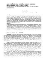
For outside diameter, inside diameter and wall thickness, t, see Figure 1.
Key
Di inside diameter (ID)
Do outside diameter (OD)
--`,,```,,,,````-`-`,,`,,`,`,,`---
Figure 1 — Round tube
2
Copyright International Organization for Standardization
Provided by IHS under license with ISO
No reproduction or networking permitted without license from IHS
© ISO 2012 – All rights reserved
Not for Resale
ISO 6363-6:2012(E)
5.2
Diameter — Round tube
Tolerances on diameter for round tubes shall be in accordance with Table 2.
Table 2 — Tolerances on diameter for round tubes
Dimensions in millimetres
Diameter
(OD or ID)
Tolerance on diameter for round tubes
Maximum allowable deviation of diameter
atanypointfromspecifieddiametera
Maximum allowable deviation of mean
diameterfromspecifieddiameter b
Alloy group Ic
Alloy group IIc
Alloy groups I and IIc
4 ≤ OD or ID ≤ 12
±0,08
±0,15
±0,08
12 < OD or ID ≤ 25
±0,10
±0,20
±0,10
25 < OD or ID ≤ 50
±0,13
±0,25
±0,13
50 < OD or ID ≤ 75
±0,15
±0,30
±0,15
75 < OD or ID ≤ 125
±0,20
±0,41
±0,20
125 < OD or ID ≤ 150
±0,25
±0,51
±0,25
150 < OD or ID ≤ 200
±0,38
±0,76
±0,38
200 < OD or ID ≤ 250
±0,51
±1,0
±0,51
250 < OD or ID ≤ 300
±0,64
±1,3
±0,64
300 < OD or ID ≤ 320
±0,76
±1,5
±0,76
Whenever the tolerance is specified only for either the plus or the minus side, the values in this table shall be doubled.
Tolerances on dimensions exceeding the specified range shall be agreed upon between the purchaser and the
supplier.
a
These values are not applied to the tubes of temper grade O, coiled tubes and tubes with wall thickness less than 2,5 % of
specified outside diameter.
b
The mean diameter is defined as the average value of measurements carried out at two arbitrary points at right angles to each
other.
c
See Table 1.
--`,,```,,,,````-`-`,,`,,`,`,,`---
3
© ISO 2012 – All rights reserved
Copyright International Organization for Standardization
Provided by IHS under license with ISO
No reproduction or networking permitted without license from IHS
Not for Resale
ISO 6363-6:2012(E)
5.3
Wall thickness — Round tube
The tolerances on wall thickness variation shall be in accordance with Table 3.
Table 3 — Tolerances on wall thickness of cold-drawn tubes
Wall thicknessa
t
Tolerance
Maximum allowable deviation of wall
thicknessatanypointfromspecifiedwall
thickness
Maximum allowable deviation of mean
wallthicknessfromspecifiedwall
thicknessb
Alloy group Ic
Alloy group IIc
Alloy groups I and IIc
±10 % of specified wall
thickness, but with
±0,08 as minimum
±0,08
0,3 ≤ t ≤ 0,8
±0,05
0,8 < t ≤ 1,2
±0,08
1,2 < t ≤ 2
±0,10
2
±0,15
3
±0,20
±0,15
5
±0,30
±0,20
7
±0,51
±0,38
9 < t ≤ 12
±0,76
±0,51
±0,05
±0,10
±0,13
12 < t ≤ 15
±1,0
±0,64
15 < t ≤ 19
±1,3
±0,76
19 < t ≤ 20
±1,5
±0,89
Whenever the tolerance is specified only for either the plus or the minus side, the values in this table shall be doubled.
Tolerances on dimensions exceeding the specified range shall be agreed upon between the purchaser and the
supplier.
a
In the case where the outside diameter and inside diameter of tube are specified, apply the tolerance value specified in the column
“Maximum allowable deviation of wall thickness at any point from specified wall thickness”, taking mean wall thickness as the wall
thickness.
b
The mean wall thickness is defined as the average value of measurements carried out at two arbitrary positions facing each other
with the pipe axis between them.
5.4
Fixed-length tolerances
Tolerances on fixed length shall be in accordance with Table 4.
4
--`,,```,,,,````-`-`,,`,,`,`,,`---
Copyright International Organization for Standardization
Provided by IHS under license with ISO
No reproduction or networking permitted without license from IHS
© ISO 2012 – All rights reserved
Not for Resale
ISO 6363-6:2012(E)
Table4—Tolerancesonfixedlength
Dimensions in millimetres
Toleranceonfixedlengths
L
Outside diameter
OD
L ≤ 3 500
3 500 < L ≤ 9 000
9 000 < L ≤ 15 000
OD ≤ 6
+7
0
+ 10
0
+ 13
0
6 < OD ≤ 75
+4
0
+7
0
+ 10
0
75 < OD ≤ 150
+5
0
+8
0
+ 11
0
Tolerances on dimensions exceeding the range of specified dimensions shall be agreed upon between the purchaser and the supplier.
5.5
Squareness of cut ends
The squareness of cut ends shall be within half of the fixed-length tolerance range specified in Table 4 for both
fixed and random lengths. For example for a fixed-length tolerance of
+ 10
0
mm, the squareness of cut ends
shall be within 5 mm.
6 Tolerances on form
6.1
General
Tolerances on form for O temper shall be subject to agreement between the purchaser and supplier.
6.2
Straightness
The straightness tolerance of round tubes is specified in Table 5.
© ISO 2012 – All rights reserved
Copyright International Organization for Standardization
Provided by IHS under license with ISO
No reproduction or networking permitted without license from IHS
--`,,```,,,,````-`-`,,`,,`,`,,`---
Not for Resale
5
ISO 6363-6:2012(E)
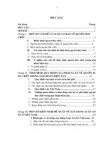
Table 5 — Tolerances on straightness of round tube
Dimensions in millimetres
Tolerances on straightness of round tubea
Outside diameter
OD
Key
1
straightness
Maximum allowable deviation of straightness Maximum allowable deviation of straightness
for any 300 mm length
for total length
Lb
OD ≤ 9
13
13 ×
L
300
9 < OD ≤ 150
0,3
0,3 ×
L
300
Tolerance on dimensions exceeding the range of specified dimensions shall be agreed upon between the purchaser
and supplier.
a
These are values obtained by placing the tube on a flat surface, so that the weight of the tube minimizes the deviation.
These values do not apply to temper grade O.
b
Whenever the total length of tube does not constitute an integral multiple of 300 mm, the tolerance is determined by rounding up
fractions to a unit for every 300 mm.
--`,,```,,,,````-`-`,,`,,`,`,,`---
6
Copyright International Organization for Standardization
Provided by IHS under license with ISO
No reproduction or networking permitted without license from IHS
© ISO 2012 – All rights reserved
Not for Resale
ISO 6363-6:2012(E)
Bibliography
[1]
Registration of International Alloy Designations and Chemical Composition Limits for Wrought
Aluminium Alloys (also known as “Teal sheets”). The Aluminum Association, Arlington, VA. Available
at: />
--`,,```,,,,````-`-`,,`,,`,`,,`---
7
© ISO 2012 – All rights reserved
Copyright International Organization for Standardization
Provided by IHS under license with ISO
No reproduction or networking permitted without license from IHS
Not for Resale
ISO 6363-6:2012(E)
ICS 23.040.15; 77.150.10
Price based on 7 pages
--`,,```,,,,````-`-`,,`,,`,`,,`---
© ISO 2012 – All rights reserved
Copyright International Organization for Standardization
Provided by IHS under license with ISO
No reproduction or networking permitted without license from IHS
Not for Resale