Tiêu chuẩn iso 04545 2 2005
Bạn đang xem bản rút gọn của tài liệu. Xem và tải ngay bản đầy đủ của tài liệu tại đây (207.96 KB, 20 trang )
INTERNATIONAL
STANDARD
ISO
4545-2
First edition
2005-11-15
Metallic materials — Knoop hardness
test —
Part 2:
Verification and calibration of testing
machines
Matériaux métalliques — Essai de dureté Knoop —
--`,,```,,,,````-`-`,,`,,`,`,,`---
Partie 2: Vérification et étalonnage des machines d'essai
Reference number
ISO 4545-2:2005(E)
Copyright International Organization for Standardization
Reproduced by IHS under license with ISO
No reproduction or networking permitted without license from IHS
© ISO 2005
Not for Resale
ISO 4545-2:2005(E)
PDF disclaimer
This PDF file may contain embedded typefaces. In accordance with Adobe's licensing policy, this file may be printed or viewed but
shall not be edited unless the typefaces which are embedded are licensed to and installed on the computer performing the editing. In
downloading this file, parties accept therein the responsibility of not infringing Adobe's licensing policy. The ISO Central Secretariat
accepts no liability in this area.
Adobe is a trademark of Adobe Systems Incorporated.
--`,,```,,,,````-`-`,,`,,`,`,,`---
Details of the software products used to create this PDF file can be found in the General Info relative to the file; the PDF-creation
parameters were optimized for printing. Every care has been taken to ensure that the file is suitable for use by ISO member bodies. In
the unlikely event that a problem relating to it is found, please inform the Central Secretariat at the address given below.
© ISO 2005
All rights reserved. Unless otherwise specified, no part of this publication may be reproduced or utilized in any form or by any means,
electronic or mechanical, including photocopying and microfilm, without permission in writing from either ISO at the address below or
ISO's member body in the country of the requester.
ISO copyright office
Case postale 56 • CH-1211 Geneva 20
Tel. + 41 22 749 01 11
Fax + 41 22 749 09 47
Web www.iso.org
Published in Switzerland
ii
Copyright International Organization for Standardization
Reproduced by IHS under license with ISO
No reproduction or networking permitted without license from IHS
© ISO 2005 – All rights reserved
Not for Resale
ISO 4545-2:2005(E)
Contents
Page
Foreword............................................................................................................................................................ iv
1
Scope ..................................................................................................................................................... 1
2
Normative references ........................................................................................................................... 1
3
General conditions ............................................................................................................................... 1
4
Direct verification.................................................................................................................................. 2
5
Indirect verification............................................................................................................................... 4
6
Intervals between verifications ........................................................................................................... 6
7
Verification report/calibration certificate ........................................................................................... 6
--`,,```,,,,````-`-`,,`,,`,`,,`---
Annex A (informative) Notes on diamond indenters ...................................................................................... 7
Annex B (informative) Uncertainty of measurement of the calibration results of the hardness
testing machine..................................................................................................................................... 8
Bibliography ..................................................................................................................................................... 14
iii
© ISO 2005 – All rights reserved
Copyright International Organization for Standardization
Reproduced by IHS under license with ISO
No reproduction or networking permitted without license from IHS
Not for Resale
ISO 4545-2:2005(E)
Foreword
ISO (the International Organization for Standardization) is a worldwide federation of national standards bodies
(ISO member bodies). The work of preparing International Standards is normally carried out through ISO
technical committees. Each member body interested in a subject for which a technical committee has been
established has the right to be represented on that committee. International organizations, governmental and
non-governmental, in liaison with ISO, also take part in the work. ISO collaborates closely with the
International Electrotechnical Commission (IEC) on all matters of electrotechnical standardization.
International Standards are drafted in accordance with the rules given in the ISO/IEC Directives, Part 2.
The main task of technical committees is to prepare International Standards. Draft International Standards
adopted by the technical committees are circulated to the member bodies for voting. Publication as an
International Standard requires approval by at least 75 % of the member bodies casting a vote.
Attention is drawn to the possibility that some of the elements of this document may be the subject of patent
rights. ISO shall not be held responsible for identifying any or all such patent rights.
ISO 4545-2 was prepared by Technical Committee ISO/TC 164, Mechanical testing of metals, Subcommittee
SC 3, Hardness testing.
ISO 4545-2 cancels and replaces ISO 4546:1993, which has been technically revised.
ISO 4545 consists of the following parts, under the general title Metallic materials — Knoop hardness test:
—
Part 1: Test method
—
Part 2: Verification and calibration of testing machines
—
Part 3: Calibration of reference blocks
—
Part 4: Table of hardness values
--`,,```,,,,````-`-`,,`,,`,`,,`---
iv
Copyright International
Organization for Standardization
Reproduced by IHS under license with ISO
No reproduction or networking permitted without license from IHS
© ISO 2005 – All rights reserved
Not for Resale
INTERNATIONAL STANDARD
ISO 4545-2:2005(E)
Metallic materials — Knoop hardness test —
Part 2:
Verification and calibration of testing machines
1
Scope
This part of ISO 4545 specifies the method of verification of testing machines for determining Knoop hardness
for metallic materials in accordance with ISO 4545-1-1. It covers test forces from 0,098 07 N to 19,614 N. The
method is recommended only for indentations with diagonals W 0,020 mm.
It specifies a direct verification method for checking the main functions of the machine, and an indirect
verification method suitable for the overall checking of the machine. The indirect verification method may be
used on its own for periodic routine checking of the machine in service.
If a testing machine is also to be used for other methods of hardness testing, it should be verified
independently for each method.
2
Normative references
The following referenced documents are indispensable for the application of this document. For dated
references, only the edition cited applies. For undated references, the latest edition of the referenced
document (including any amendments) applies.
ISO 376:2004, Metallic materials — Calibration of force-proving instuments used for the verification of uniaxial
testing machines
ISO 4545-1:2005, Metallic materials — Knoop hardness test — Part 1: Test method
ISO 4545-3, Metallic materials — Knoop hardness test — Part 3: Calibration of reference blocks
3
General conditions
Before a Knoop hardness testing machine is verified, it shall be checked to ensure that it is properly set up in
accordance with the manufacturer's instructions.
Especially, it should be checked that:
a)
the mount holding the indenter is capable of moving freely without any friction or excess side play;
b)
the indenter is firmly mounted in the mount;
c)
the test force can be applied and removed without shock or vibration and in such a manner that the
readings are not influenced;
1
© ISO 2005 – All rights reserved
--`,,```,,,,````-`-`,,`,,`,`,,`---
Copyright International Organization for Standardization
Reproduced by IHS under license with ISO
No reproduction or networking permitted without license from IHS
Not for Resale
ISO 4545-2:2005(E)
4
the measuring system is integral with the machine:
⎯
the change in mode from the application and removal of the test force to the measuring mode does
not influence the readings,
⎯
illumination does not affect the readings,
⎯
the centre of the indentation is near the centre of the field of view.
Direct verification
4.1
General
4.1.1 Direct verification should be carried out at a temperature of (23 ± 5) °C. If the verification is carried out
at a temperature outside this range, it shall be noted in the verification report.
4.1.2
The instruments used for verification and calibration shall be traceable to national standards.
4.1.3
Direct verification involves:
a)
calibration of the test force;
b)
verification of the indenter;
c)
calibration of the measuring system;
d)
verification of the testing cycle.
4.2
Calibration of the test force
4.2.1 Each test force used (see Table 2 in ISO 4545-1:2005), within the working range of the testing
machine, shall be measured.
4.2.2
The test force shall be measured by one of the following two methods:
⎯
by means of an elastic proving device in accordance with ISO 376:2004, class 1, or
⎯
by balancing against a force, accurate to ± 0,2 %, applied by means of calibrated masses or another
method with the same accuracy.
4.2.3 Three readings shall be taken for each test force. Immediately before each reading is taken, the
indenter shall be moved in the same direction as during the test. All readings shall be within the tolerances
defined in Table 1.
Table 1 — Test-force tolerances
4.3
4.3.1
Test force, F
Tolerance
N
%
0,098 07 u F < 1,961
± 1,5
1,961 u F u 19,614
± 1,0
Verification of the indenter
The four faces of the diamond pyramid shall be polished and free from surface defects.
2
Copyright International Organization for Standardization
Reproduced by IHS under license with ISO
No reproduction or networking permitted without license from IHS
© ISO 2005 – All rights reserved
Not for Resale
--`,,```,,,,````-`-`,,`,,`,`,,`---
d)
ISO 4545-2:2005(E)
4.3.2 Verification of the shape of the indenter can be made by direct measurement or optical measurement.
The device used for the verification shall be accurate to within ± 0,07°.
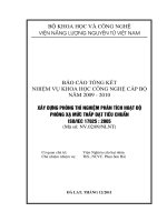
4.3.3 The angle α between the opposite edges at the vertex of the diamond pyramid shall be (172,5 ± 0,1)°
(see Figure 1).
4.3.4 The angle β between the opposite edges at the vertex of the diamond pyramid shall be (130 ± 1,0)°
(see Figure 1).
4.3.5 The indenter constant c (see ISO 4545-1:2005, Table 1) shall be within 1,0 % of the ideal value
0,070 28, (0,069 58 u c u 0,070 98).
NOTE
To achieve the tolerances for the indenter constant c, the values of angle α and/or angle β may be kept to
closer tolerances than given above.
4.3.6 The angle between the axis of the diamond pyramid and the axis of the indenter holder (normal to the
seating surface) shall be within ± 0,5°.
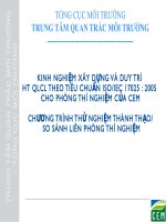
4.3.7 The four faces shall meet at a common point. The maximum permissible length of the line of
conjunction between opposite faces shall be less than 1,0 µm (see Figure 2).
NOTE
For indents less than 0,020 mm, the maximum permissible length of the line of conjunction should be
proportionally less. The line of conjunction may be determined by measuring an indentation.
4.4
Calibration of the measuring system
--`,,```,,,,````-`-`,,`,,`,`,,`---
4.4.1 The system for measuring the long diagonal of the indentation shall be calibrated at each
magnification to be used against an accurately ruled line scale (object micrometer) or system of equivalent
accuracy. The errors of the line scale shall be known within an uncertainty of 0,1 µm or 0,05 %, whichever is
greater.
4.4.2 The measuring system shall be verified by measurements made on a stage micrometer at a minimum
of five intervals over each working range.
Figure 1 — Principle of the test and indenter geometry
3
© ISO 2005 – All rights reserved
Copyright International Organization for Standardization
Reproduced by IHS under license with ISO
No reproduction or networking permitted without license from IHS
Not for Resale
ISO 4545-2:2005(E)
Dimensions in µm
Figure 2 — Line of conjunction on the top of the indenter (schematic)
4.4.3 The maximum permissible error of the measuring system shall be ± 0,5 % or 0,4 µm, whichever is
greater. If necessary, a calibration factor can be applied to comply with this tolerance.
4.5
Verification of the testing cycle
The testing cycle shall be timed with an uncertainty of 1 s and shall conform to the testing cycle of ISO 4545-1.
5
Indirect verification
5.1 Indirect verification should be carried out at a temperature of (23 ± 5) °C by means of reference blocks
calibrated in accordance with ISO 4545-3. If the verification is carried out at a temperature outside this range,
it shall be noted in the verification report.
5.2 On each reference block, measure the reference indentation. For each block, the difference between
the mean measured value and the certified long diagonal shall not exceed the greater of 0,5 % and 0,4 µm.
5.3 When verifying testing machines used for several test forces, all used forces shall be chosen. One of
the forces shall be the lowest force used and the other force shall be chosen within the upper half of those
used. For each test force chosen, two different reference blocks shall be chosen within the range for which the
machine is used. The ratio of the hardness values for the two blocks shall be equal to or greater than 2.
5.4 When verifying testing machines used for only one test force, three reference blocks shall be used,
uniformly distributed over the range of the machine.
5.5 On each reference block, five indentations shall be made and measured. The tests shall be carried out
in accordance with ISO 4545-1.
5.6 For each reference block, let d1, d2, …, d5 be the values of the measured diagonals of the indentations,
arranged in increasing order of magnitude, and
d + d 2 + ... + d 5
d = 1
5
5.7
(1)
The repeatability r of the testing machine, under the particular verification conditions, is calculated as:
r = d 5 − d1
(2)
--`,,```,,,,````-`-`,,`,,`,`,,`---
4
Copyright International Organization for Standardization
Reproduced by IHS under license with ISO
No reproduction or networking permitted without license from IHS
© ISO 2005 – All rights reserved
Not for Resale
ISO 4545-2:2005(E)
The repeatability, expressed as a percentage of d , is calculated as:
d − d1
rrel = 100 5
d
(3)
The repeatability of the testing machine is satisfactory if r u 0,001 mm. If r > 0,001 mm, the repeatability of the
testing machine is satisfactory when rrel is less than or equal to the percentages indicated in Table 2.
--`,,```,,,,````-`-`,,`,,`,`,,`---
Table 2 — Relative repeatability
Hardness range of
standardized test blocks
Test force
Maximum permissible rrel
N
%
100 u HK u 250
250 < HK u 650
9
0,098 07 u F u 4,903
5
HK > 650
4
100 u HK u 250
8
250 < HK u 650
4,903 < F u 19,614
HK > 650
5
4
HK: Knoop hardness
5.8 The error, E, of the testing machine under the particular verification conditions is calculated by the
following formula:
E = d − dc
(4)
The percent error, Erel, is calculated by the following equation:
E rel = 100
d − dc
dc
(5)
where dc is the reported certified mean diagonal length for the reference block, in millimetres.
The error of the testing machine is satisfactory if E u ± 0,000 5 mm. If E > 0,000 5 mm, the error of the testing
machine is satisfactory when Erel u ± 2 %.
5.9 The determination of the uncertainty of measurement of the calibration results of the hardness testing
machine is given in Annex B.
5
© ISO 2005 – All rights reserved
Copyright International Organization for Standardization
Reproduced by IHS under license with ISO
No reproduction or networking permitted without license from IHS
Not for Resale
ISO 4545-2:2005(E)
6
Intervals between verifications
The specifications for the direct verifications of hardness testing machines are given in Table 3.
Table 3 — Direct verifications of hardness testing machines
Force
Measuring
system
Test cycle
Indenter a
before setting to work first time
x
x
x
x
after dismantling and reassembling, if force,
measuring system or test cycle are affected
x
x
x
failure of indirect verificationb
x
x
x
indirect verification > 14 months ago
x
x
x
Requirements of verification
a
In addition, it is recommended that the indenter be directly verified after 2 years of use.
b
Direct verification of these parameters may be carried out sequentially (until the machine passes indirect verification) and is not
required if it can be demonstrated (e.g. by tests with a reference indenter) that the indenter was the cause of the failure.
7
Verification report/calibration certificate
The verification report/calibration certificate shall contain the following information:
a)
a reference to this part of ISO 4545;
b)
method of verification (direct and/or indirect);
c)
identification data of the hardness testing machine;
d)
means of verification (reference blocks, elastic proving devices, etc.);
e)
test force(s) used;
f)
hardness values of standardized blocks used;
g)
verification temperature, if it is outside the range specified in Clause 4;
h)
the result obtained;
i)
date of verification and reference to the verification institution;
j)
uncertainty of the verification result.
6
Copyright International Organization for Standardization
Reproduced by IHS under license with ISO
No reproduction or networking permitted without license from IHS
© ISO 2005 – All rights reserved
Not for Resale
--`,,```,,,,````-`-`,,`,,`,`,,`---
Indirect verification shall be performed at least once every 12 months and after a direct verification has been
performed.
ISO 4545-2:2005(E)
Annex A
(informative)
Notes on diamond indenters
Experience has shown that a number of initially satisfactory indenters can become defective after use for a
comparatively short time. This is due to small cracks, pits or other flaws in the surface. If such faults are
detected in time, regrinding may reclaim many indenters. If not, any small defects on the surface rapidly
worsen and make the indenter useless.
Therefore,
⎯
the condition of indenters should be monitored by visually checking the appearance of the indentation on
a reference block, each day the testing machine is used;
⎯
the verification of the indenter is no longer valid when the indenter shows defects;
⎯
reground or otherwise repaired indenters shall meet all of the requirements of 4.3.
--`,,```,,,,````-`-`,,`,,`,`,,`---
7
© ISO 2005 – All rights reserved
Copyright International Organization for Standardization
Reproduced by IHS under license with ISO
No reproduction or networking permitted without license from IHS
Not for Resale
ISO 4545-2:2005(E)
Annex B
(informative)
Uncertainty of measurement of the calibration results of the hardness
testing machine
The metrological chain necessary to define and disseminate hardness scales is shown in Figure B.1 in
ISO 4545-1:2005.
B.1 Direct calibration of the hardness testing machine
B.1.1 Calibration of the test force
The combined relative standard uncertainty of the test force calibration is calculated according to the following
equation:
2
2
uF = u FRS
+ uFHTM
(B.1)
where
uFRS
is the relative uncertainty of measurement of the force transducer (from calibration certificate);
uFHTM is the relative standard uncertainty of the test force generated by the hardness testing machine.
The uncertainty of measurement of the reference instrument, force transducer, is indicated in the
corresponding calibration certificate. The influence quantities, like
⎯
temperature dependence,
⎯
long-term stability, and
⎯
interpolation deviation,
should be considered for critical applications. Depending on the design of the force transducer, the rotational
position of the transducer related to the indenter axis of the hardness testing machine should be considered.
EXAMPLE
Uncertainty of measurement of the force transducer (from calibration certificate):
UFRS = 0,24 % (k = 2)
Calibration value of the force transducer
FRS = 9,806 7 N
Table B.1 — Results of the test force calibration
Number of height
position for test force
calibration
Series 1, F1
Series 2, F2
Series 3, F3
Mean value
N
N
N
F, N
1
9,809
9,815
9,822
9,815
Relative
deviation
∆Frel, %
0,08
Relative
standard
measurement
uncertainty
uFHTM, %
0,04
--`,,```,,,,````-`-`,,`,,`,`,,`---
8
Copyright International Organization for Standardization
Reproduced by IHS under license with ISO
No reproduction or networking permitted without license from IHS
© ISO 2005 – All rights reserved
Not for Resale
ISO 4545-2:2005(E)
where
∆Frel =
FRS − F
F
sFi
u FHTM =
F
⋅
(B.2)
1
, ( n = 3)
n
(B.3)
sFi is the standard deviation of the test-force indication values in the i-th height position
Quantity Xi
Estimated
value xi
uFRS
294,2 N
Relative limit
values ai
uFHTM
Distribution
type
Relative
standard
measurement
uncertainty
u(xi)
Sensitivity
coefficient ci
Relative
uncertainty
contribution
ui(H)
Normal
1,2 × 10⁻³
1
1,2 × 10⁻³
Normal
4,0 × 10⁻⁴
1
4,0 × 10⁻⁴
Relative combined standard uncertainty u(F)
1,26 × 10⁻³
Relative expanded uncertainty of measurement U(F) (k = 2)
2,5 × 10⁻³
Table B.3 — Calculation of the maximum relative deviation of the test force including the uncertainty
of measurement of the reference instrument
Relative deviation of test force
∆Frel,
Expanded relative measurement
uncertainty of test force UF,
%
%
0,08
0,25
Max. relative deviation of test force
including measurement uncertainty
of reference instrument ∆Fmax,
%
0,33
where
∆Fmax = ∆Frel + U F
(B.4)
The result of the example means that the deviation of the test forces including the uncertainty of measurement
of the reference instrument specified in 4.2.3, amounting to ± 1,0 % is complied with.
B.1.2 Calibration of the optical measuring system
The combined relative standard uncertainty of the reference instrument for the measuring system is calculated
as follows:
2
2
2
u L = u LRS
+ u ms
+ u LHTM
(B.5)
where
uLRS
is the relative uncertainty of measurement of the object micrometer (reference standard) from the
calibration certificate for k = 1;
ums
is the uncertainty of measurement due to the resolution of the measuring system;
uLHTM
is the relative standard uncertainty of measurement of the hardness testing machine.
9
© ISO 2005 – All rights reserved
Copyright International Organization for Standardization
Reproduced by IHS under license with ISO
No reproduction or networking permitted without license from IHS
Not for Resale
--`,,```,,,,````-`-`,,`,,`,`,,`---
Table B.2 — Calculation of the uncertainty of measurement of the test force
ISO 4545-2:2005(E)
The uncertainty of measurement of the reference instrument for the optical measuring system, the object
micrometer, is indicated in the corresponding calibration certificate. The influence quantities, for example,
⎯
temperature dependence,
⎯
longterm stability, and
⎯
interpolation deviation,
do not exert an essential influence on the uncertainty of measurement of the object micrometer.
EXAMPLE
Uncertainty of measurement of the object micrometer:
ULRS = 0,000 5 mm (k = 2)
Resolution of the measuring system
δms = 0,1 µm
Table B.4 — Results of the calibration of the measuring system
Indication value of the
object micrometer LRS,
Series 1,
L
Series 2,
L2
Series 3,
L3,
Mean value,
L
Relative
deviation
Relative
standard
measurement
uncertainty
mm
mm
mm
mm
mm
∆Lrel, %
uLHTM, %
0,05
0,050 1
0,050 0
0,050 1
0,050 1
0,13
0,07
0,10
0,100 2
0,100 0
0,100 1
0,100 1
0,10
0,06
0,20
0,200 1
0,199 5
0,200 1
0,199 9
−0,05
0,10
0,30
0,299 7
0,300 1
0,300 1
0,300 0
−0,01
0,01
0,40
0,400 2
0,400 9
0,400 7
0,400 6
0,15
0,05
where
u LHTM =
∆Lrel =
sLi
L
⋅
1
n
, ( n = 3)
(B.6)
L − LRS
LRS
(B.7)
sLi is the standard deviation of the length indication values for the i-th indication value of the object
micrometer.
Table B.5 — Calculation of the uncertainty of measurement of the measuring system
Quantity Xi
Estimated
value xi
uLRS rel
0,40 mm
ums rel
uLHTM
Limit value ai
3,5 × 10⁻⁴
0,40 mm
Distribution
type
Relative
standard
measurement
uncertainty
u(xi)
Sensitivity
coefficient ci
Relative
uncertainty
contribution
ui(H)
Normal
6,25 × 10⁻⁴
1
6,25 × 10⁻⁴
Rectangular
0,7 × 10⁻⁴
1
0,7 × 10⁻⁴
Normal
10,0 × 10⁻⁴
1
10,0 × 10⁻⁴
Relative combined uncertainty of measurement uL, %
0,12
Relative expanded uncertainty of measurement UL (k = 2), %
0,24
10
Copyright International Organization for Standardization
Reproduced by IHS under license with ISO
No reproduction or networking permitted without license from IHS
--`,,```,,,,````-`-`,,`,,`,`,,`---
© ISO 2005 – All rights reserved
Not for Resale
ISO 4545-2:2005(E)
Table B.6 — Calculation of the maximum relative deviation of the measuring system including the
uncertainty of measurement of the length reference instrument
Test length
LRS
Relative deviation of the
measuring system
∆Lrel, %
Expanded relative
uncertainty of
measurement
UL, %
0,40 mm
0,15
0,24
Max. relative deviation of
measuring system
including measurement
uncertainty of length
reference instrument
∆Lmax, %
0,39
where
∆Lmax = ∆Lrel + U L
(B.8)
The result of the example means that the deviation of the measuring system, including the uncertainty of
measurement of the length reference instrument specified in 4.4.3 amounting to ± 0,5 % is complied with.
B.1.3 Verification of the indenter
The indenter, consisting of indenter tip and holder, cannot be verified, respectively calibrated, in-site. A valid
calibration certificate of an accredited calibration laboratory shall exist which confirms the geometrical
deviations of the indenter (see 4.3).
B.1.4 Verification of the test cycle
In 4.4 the permissible deviation for every section of the test cycle is stipulated as ± 0,5 s. While measuring
with a usual time measuring system (stopwatch), the uncertainty of measurement can be indicated as 0,1 s.
Therefore, an estimation of the uncertainty of measurement is not necessary.
B.2 Indirect verification of the hardness testing machine
NOTE
In this Annex the index “CRM (Certified Reference Material)” means, according to the definitions of the
hardness testing standards, “Hardness Reference Block”.
The uncertainty of measurement of the indirect verification of the hardness testing machine follows from the
equation:
2
2
2
u HTM = u CRM
+ u CRM-D
+ u H2 + u ms
(B.9)
where
uCRM
is the calibration uncertainty of the hardness reference block according to the calibration
certificate for k = 1;
uCRM-D
is the hardness change of the hardness reference block since its last calibration due to drift
(negligible for use of the hardness reference block complying with the standard);
uH
is the standard uncertainty of hardness testing machine when measuring CRM;
ums
is the uncertainty due to the resolution of the hardness testing machine.
11
© ISO 2005 – All rights reserved
Copyright International Organization for Standardization
Reproduced by IHS under license with ISO
No reproduction or networking permitted without license from IHS
Not for Resale
--`,,```,,,,````-`-`,,`,,`,`,,`---
By indirect verification with hardness reference blocks, the overall function of the hardness testing machine is
checked and the repeatability, as well as the deviation of the hardness testing machine from the real hardness
value, are determined.
--`,,```,,,,````-`-`,,`,,`,`,,`---
ISO 4545-2:2005(E)
EXAMPLE
Hardness of the hardness reference block
HCRM = (802,7 ± 12,0) HK1
Uncertainty of measurement of the hardness reference block
UCRM = ± 12,0 HK1
Resolution of the hardness testing machine
δms = 0,1 µm
Table B.7 — Results of the indirect verification
Measured indentation diagonal, d
Calculated hardness value, H
mm
HKa
1
0,133 2
802,0
2
0,133 3
800,8
3
0,133 5max
798,4min
4
0,133 0min
804,4max
5
0,133 1
803,2
Mean value H
0,133 2
801,7
No.
Standard deviation sH
a
2,3
HK: Knoop hardness
b = H − H CRM
(B.10)
= 801,7 − 802,7 = − 1,0 HK
uH =
t ⋅ sH
(B.11)
n
For t = 1,14, n = 5 and sH = 2,3 HK follows:
uH = 1,18 HK
B.3 Budget of uncertainty of measurement
Table B.8 — Budget of uncertainty of measurement
Quantity Xi
Estimated value
xi
Standard
uncertainty of
measurement
u(xi)
Distribution type
Sensitivity
coefficient ci
Uncertainty
contribution ui(H)
uCRM
402,7 HK
6,0 HK
Normal
1,0
6,0 HK
uH
0 HK
1,18 HK
Normal
1,0
1,18 HK
ums
0 HK
0,000 029 mm
Rectangular
4 284,6a
0,00 HK
uCMR-D
0 HK
0 HK
Triangular
1,0
0 HK
Combined uncertainty of measurement uHTM
6,12 HK
Expanded uncertainty of measurement UHTM (k = 2)
12,2 HK
HK: Knoop hardness
a
c = ∂H/∂d = 2(H/d) for H = 801,7 HK1 and d = 0,133 1 mm
12
Copyright International Organization for Standardization
Reproduced by IHS under license with ISO
No reproduction or networking permitted without license from IHS
© ISO 2005 – All rights reserved
Not for Resale
ISO 4545-2:2005(E)
Table B.9 — Maximum deviation of the hardness testing machine including the uncertainty of
measurement
Measured hardness on the
hardness testing machine
H
Expanded uncertainty of
measurement UHTM
Deviation of the testing
machine when calibrating
with the reference block
b
Maximum deviation of the
testing machine including
uncertainty of
measurement ∆HHTMmax
HK
HK
HK
HK
801,7 HK1
12,2
1,0
13,2
HK: Knoop hardness
where
b = H − H CRM
(B.12)
∆HHTMmax = UHTM + ∆HHTM = 12,2 + 1,0 = 13,2 HK
--`,,```,,,,````-`-`,,`,,`,`,,`---
The result of the example above means that the permissible limit deviation of the testing machine, including
the uncertainty of measurement of the testing machine specified in 5.8 amounting to ± 2 %, is complied with.
13
© ISO 2005 – All rights reserved
Copyright International Organization for Standardization
Reproduced by IHS under license with ISO
No reproduction or networking permitted without license from IHS
Not for Resale
ISO 4545-2:2005(E)
Bibliography
A. SAWLA: Uncertainty of measurement in the verification and calibration of the force measuring
systems of testing machines, Proceedings of the Asia-Pacific symposium on measurement of force,
mass and torque (APMF), Tsukuba, Japan, November 2000
[2]
A. W EHRSTEDT, I. PATKOVSZKY: News in the field of standardization about verification and calibration of
materials testing machines, May 2001, EMPA Academy 2001
[3]
W. GABAUER: Manual codes of practice for the determination of uncertainties in mechanical tests on
metallic materials, The estimation of uncertainties in hardness measurements, Project No. SMT4CT97-2165, UNCERT COP 14:2000
[4]
T. POLZIN, D. SCHWENK: Method for Uncertainty Determination of Hardness Testing; PC File for
Determination, Materialprüfung 44 (2002) 3, pp. 64-71
14
© ISO 2005 – All rights reserved
--`,,```,,,,````-`-`,,`,,`,`,,`---
[1]
Copyright International Organization for Standardization
Reproduced by IHS under license with ISO
No reproduction or networking permitted without license from IHS
Not for Resale
--`,,```,,,,````-`-`,,`,,`,`,,`---
Copyright International Organization for Standardization
Reproduced by IHS under license with ISO
No reproduction or networking permitted without license from IHS
Not for Resale
ISO 4545-2:2005(E)
--`,,```,,,,````-`-`,,`,,`,`,,`---
ICS 77.040.10
Price based on 14 pages
© ISO 2005 – All rights reserved
Copyright International Organization for Standardization
Reproduced by IHS under license with ISO
No reproduction or networking permitted without license from IHS
Not for Resale