Tiêu chuẩn iso 03548 3 2012
Bạn đang xem bản rút gọn của tài liệu. Xem và tải ngay bản đầy đủ của tài liệu tại đây (539.93 KB, 44 trang )
INTERNATIONAL
STANDARD
ISO
3548-3
First edition
2012-12-01
Plain bearings — Thin-walled half
bearings with or without flange —
Part 3:
Measurement of peripheral length
Paliers lisses — Demi-coussinets minces à collerette ou sans collerette —
Partie 3: Mesurage de la longueur développée
--``,,,``,,`,```,,,,`,```,```,,,-`-`,,`,,`,`,,`---
Reference number
ISO 3548-3:2012(E)
Copyright International Organization for Standardization
Provided by IHS under license with ISO
No reproduction or networking permitted without license from IHS
Licensee=University of Alberta/5966844001, User=sharabiani, shahramfs
Not for Resale, 12/02/2013 04:54:36 MST
© ISO 2012
ISO 3548-3:2012(E)
COPYRIGHT PROTECTED DOCUMENT
© ISO 2012
All rights reserved. Unless otherwise specified, no part of this publication may be reproduced or utilized in any form or by any
means, electronic or mechanical, including photocopying and microfilm, without permission in writing from either ISO at the
address below or ISO’s member body in the country of the requester.
ISO copyright office
Case postale 56 • CH-1211 Geneva 20
Tel. + 41 22 749 01 11
Fax + 41 22 749 09 47
Web www.iso.org
Published in Switzerland
ii
--``,,,``,,`,```,,,,`,```,```,,,-`-`,,`,,`,`,,`---
Copyright International Organization for Standardization
Provided by IHS under license with ISO
No reproduction or networking permitted without license from IHS
© ISO 2012 – All rights reserved
Licensee=University of Alberta/5966844001, User=sharabiani, shahramfs
Not for Resale, 12/02/2013 04:54:36 MST
ISO 3548-3:2012(E)
Contents
Page
Foreword ..........................................................................................................................................................................................................................................v
2
3
4
5
6
7
8
9
10
11
12
13
14
15
16
17
Scope ................................................................................................................................................................................................................................. 1
Normative references ...................................................................................................................................................................................... 1
Terms and definitions ..................................................................................................................................................................................... 1
Symbols .......................................................................................................................................................................................................................... 2
Purpose of checking .......................................................................................................................................................................................... 3
Checking methods ............................................................................................................................................................................................... 4
6.1
Method A ...................................................................................................................................................................................................... 4
6.2
Method B ...................................................................................................................................................................................................... 4
Choice and designation of checking method ........................................................................................................................... 5
7.1
Choice of checking method........................................................................................................................................................... 5
7.2
Designation of checking method ............................................................................................................................................. 6
Measuring equipment ..................................................................................................................................................................................... 6
Measuring equipment requirements .............................................................................................................................................. 8
9.1
General ........................................................................................................................................................................................................... 8
9.2
Tolerance on checking load setting ....................................................................................................................................... 8
9.3
Speed of approach of measuring head ............................................................................................................................... 9
9.4
Construction of measuring head ............................................................................................................................................. 9
9.5
Accuracy of the measuring plane for metering bars .............................................................................................. 9
9.6
Accuracy of the dial gauge............................................................................................................................................................. 9
Gauging tools for establishing the datum................................................................................................................................... 9
10.1 General ........................................................................................................................................................................................................... 9
10.2 Master checking block (used alone) .................................................................................................................................. 10
10.3 Series checking block used alone......................................................................................................................................... 10
10.4 Series checking block with master shell ........................................................................................................................ 10
Checking block requirements ..............................................................................................................................................................10
11.1 General ........................................................................................................................................................................................................ 10
11.2 Reference tooling: master checking block — General ....................................................................................... 11
11.3 Series gauging tools ......................................................................................................................................................................... 13
Master shell and comparison shell requirements ..........................................................................................................15
12.1 Master shell requirements ......................................................................................................................................................... 15
12.2 Comparison shell requirements............................................................................................................................................ 17
Correction factors .............................................................................................................................................................................................18
13.1 Reference tooling: master checking block correction factor, Fcor,cbm .................................................... 18
13.2 Series control tooling ..................................................................................................................................................................... 18
13.3 Marking ...................................................................................................................................................................................................... 19
13.4 Reference setting................................................................................................................................................................................ 19
Typical checking procedure...................................................................................................................................................................19
Conditions of the half bearings to be checked ....................................................................................................................20
Measuring errors ..............................................................................................................................................................................................20
16.1 Errors due to measuring equipment................................................................................................................................. 20
16.2 Errors due to the checking block.......................................................................................................................................... 20
16.3 Errors due to the correction factor..................................................................................................................................... 21
16.4 Errors due to the half bearing ................................................................................................................................................. 21
16.5 Error due to the choice of checking method .............................................................................................................. 21
Accuracy of methods used .......................................................................................................................................................................21
17.1 Checking conditions ........................................................................................................................................................................ 21
© ISO 2012 – All rights reserved
Copyright International Organization for Standardization
Provided by IHS under license with ISO
No reproduction or networking permitted without license from IHS
Licensee=University of Alberta/5966844001, User=sharabiani, shahramfs
Not for Resale, 12/02/2013 04:54:36 MST
iii
--``,,,``,,`,```,,,,`,```,```,,,-`-`,,`,,`,`,,`---
1
ISO 3548-3:2012(E)
18
19
17.2
17.3
Limits............................................................................................................................................................................................................ 21
Calculation ............................................................................................................................................................................................... 21
Specifications on bearing drawings...............................................................................................................................................21
Specifications for the control of the checking means .................................................................................................21
Annex B (normative) Determination of the correction factor of the master checking block —
Method B ....................................................................................................................................................................................................................27
Annex C (normative) Determination of the correction factor of the series checking block
used alone.................................................................................................................................................................................................................31
Annex D (normative) Determination of the correction factor of the master shell or
comparison shell ...............................................................................................................................................................................................33
Annex E (normative) Tests and calculation of repeatability, reproducibility and comparability .....35
iv
Copyright International Organization for Standardization
Provided by IHS under license with ISO
No reproduction or networking permitted without license from IHS
© ISO 2012 – All rights reserved
Licensee=University of Alberta/5966844001, User=sharabiani, shahramfs
Not for Resale, 12/02/2013 04:54:36 MST
--``,,,``,,`,```,,,,`,```,```,,,-`-`,,`,,`,`,,`---
Annex A (normative) Determination of the correction factor of the master checking block —
Method A ....................................................................................................................................................................................................................23
ISO 3548-3:2012(E)
Foreword
ISO (the International Organization for Standardization) is a worldwide federation of national standards
bodies (ISO member bodies). The work of preparing International Standards is normally carried out
through ISO technical committees. Each member body interested in a subject for which a technical
committee has been established has the right to be represented on that committee. International
organizations, governmental and non-governmental, in liaison with ISO, also take part in the work.
ISO collaborates closely with the International Electrotechnical Commission (IEC) on all matters of
electrotechnical standardization.
International Standards are drafted in accordance with the rules given in the ISO/IEC Directives, Part 2.
The main task of technical committees is to prepare International Standards. Draft International
Standards adopted by the technical committees are circulated to the member bodies for voting.
Publication as an International Standard requires approval by at least 75 % of the member bodies
casting a vote.
Attention is drawn to the possibility that some of the elements of this document may be the subject of
patent rights. ISO shall not be held responsible for identifying any or all such patent rights.
ISO 3548-3 was prepared by Technical Committee ISO/TC 123, Plain Bearings, Subcommittee SC 5,
Quality analysis and assurance.
This first edition of ISO 3548-3 cancels and replaces ISO 6524:1992, which has been technically revised.
ISO 3548 consists of the following parts, under the general title Plain bearings — Thin walled half bearings
with or without flange:
— Part 1: Tolerances, design features and methods of test
— Part 2: Measurement of wall thickness and flange thickness
— Part 3: Measurement of peripheral length
--``,,,``,,`,```,,,,`,```,```,,,-`-`,,`,,`,`,,`---
© ISO 2012 – All rights reserved
Copyright International Organization for Standardization
Provided by IHS under license with ISO
No reproduction or networking permitted without license from IHS
Licensee=University of Alberta/5966844001, User=sharabiani, shahramfs
Not for Resale, 12/02/2013 04:54:36 MST
v
--``,,,``,,`,```,,,,`,```,```,,,-`-`,,`,,`,`,,`---
Copyright International Organization for Standardization
Provided by IHS under license with ISO
No reproduction or networking permitted without license from IHS
Licensee=University of Alberta/5966844001, User=sharabiani, shahramfs
Not for Resale, 12/02/2013 04:54:36 MST
INTERNATIONAL STANDARD
ISO 3548-3:2012(E)
Plain bearings — Thin-walled half bearings with or
without flange —
Part 3:
Measurement of peripheral length
1 Scope
This part of ISO 3548 specifies, according to ISO 12301, the checking of the peripheral length of thinwalled half bearings with or without flange, and describes the necessary checking methods and
measuring equipment.
Thin-walled half bearings are flexible and, in the free condition, do not conform to a cylindrical profile.
This is one reason the peripheral length of the half bearings can only be measured under a constraining
load by use of specialized measuring equipment.
In addition, measuring equipment different from that illustrated in this part of ISO 3548 can be used,
provided the measuring accuracy of the equipment is consistent with the specifications given in Clause 17.
This part of ISO 3548 does not include measurement of the parting line taper.
This part of ISO 3548 applies to thin-walled half bearings, the specifications of which are given in ISO 3548-1.
2 Normative references
The following documents, in whole or in part, are normatively referenced in this document and are
indispensable for its application. For dated references, only the edition cited applies. For undated
references, the latest edition of the referenced document (including any amendments) applies.
ISO 12301, Plain bearings — Quality control techniques and inspection of geometrical and material quality
characteristics
3 Terms and definitions
For the purposes of this document, the following terms and definitions apply.
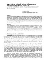
3.1
peripheral length
circumferential length, which runs from one parting line face to the other
3.2
crush height
a
value by which a half bearing, fitted in a checking block of bore diameter, dcb, under a
predetermined checking load, F, exceeds the defined peripheral length of the checking block bore
See Figure 1.
NOTE
In practice, the datum serves as a basis for measuring a (see Figure 1).
© ISO 2012 – All rights reserved
Copyright International Organization for Standardization
Provided by IHS under license with ISO
No reproduction or networking permitted without license from IHS
1
Licensee=University of Alberta/5966844001, User=sharabiani, shahramfs
Not for Resale, 12/02/2013 04:54:36 MST
--``,,,``,,`,```,,,,`,```,```,,,-`-`,,`,,`,`,,`---
ISO 3548-1, Plain bearings — Thin-walled half bearings with or without flange — Tolerances, design features
and methods of test
ISO 3548-3:2012(E)
Figure 1 — Crush height, a
3.3
repeatability
closeness of agreement between successive results obtained with the same method on the same test
piece, under the same conditions (same operator, same measuring equipment, same checking place and
time intervals)
Repeatability is assessed from the standard deviation of repeatability σΔ (see Annex E).
NOTE
3.4
reproducability
closeness of agreement between individual results obtained with the same method on the same test
piece but under different conditions (identical or different operator, measurement equipment, checking
place and times)
NOTE
For the purposes of this part of ISO 3548, reproducibility is the difference between the two averages
obtained from two sets of measuring equipment (see Annex E).
3.5
comparability
accuracy in the case of operators working in different checking places at different periods and each of
them achieving individual results, one using method A and the other using method B, on the same plain
bearing test piece in different checking blocks
NOTE
Comparability is assessed from the difference between the two averages obtained from the two
methods (see Annex E).
4 Symbols
For the purposes of this document, the following symbols apply.
Table 1 — Symbols and units
Symbol
aA or aB1+aB2
B
B1
B2
B3
Bms
dcb
Dbs
2
Parameter
Unit
Crush height
mm
Checking block width
mm
Width of the half bearing without flange
mm
Checking block width (construction for flanged half bearings)
Checking block width (construction for half bearings without flange)
Master shell width
Diameter of the checking block bore
Outside diameter of the half bearing to be checked
Copyright International Organization for Standardization
Provided by IHS under license with ISO
No reproduction or networking permitted without license from IHS
--``,,,``,,`,```,,,,`,```,```,,,-`-`,,`,,`,`,,`---
mm
mm
mm
mm
mm
© ISO 2012 – All rights reserved
Licensee=University of Alberta/5966844001, User=sharabiani, shahramfs
Not for Resale, 12/02/2013 04:54:36 MST
ISO 3548-3:2012(E)
Table 1 (continued)
Parameter
Dms
Outside diameter of the master shell
E
F
F = F1 = F 2
Fcor
H
Hcb
MPa
Correction factor
mm
Friction coefficient in calculation of deflection under load
Checking load
K2
mm
Checking block chamfer (construction for half bearings without flange)
mm
Checking block chamfer (construction for flanged half bearings)
L
Δl
scs
µm
Wall thickness of the master shell
s tot
Total wall thickness of the half bearing
U
Uncertainty of measurement
W
Width of the metering bar contact area
Z
δ
Distance between flanges of the flanged half bearing
δx
Correction, estimated by calculation
Empirical correction to compensate for the difference in elastic deflections under load between method A and method B
σ
mm
Surface roughness
Wall thickness of the comparison shell
sms
mm
mm
Elastic depression of the metering bar
Ra
mm
Peripheral length
Deviation of the actual peripheral length of the checking block
pE
N
Fillet radius between back and flange on flanged half bearing
Elastic deformation of the height of the checking block under load
K1
mm
Elasticity modulus
Distance from the bottom of the checking block bore to the datum face
ΔHcb
Unit
Standard deviation
The characteristic subscripts are given in Table 2.
--``,,,``,,`,```,,,,`,```,```,,,-`-`,,`,,`,`,,`---
Symbol
mm
mm
mm
mm
mm
mm
mm
mm
mm
mm
Table 2 — Subscripts
Subscript
bs
bearing to be checked
cbs
series checking block
cb
cbm
cs
M
ms
th
5 Purpose of checking
checking block
master checking block
comparison shell
measured
master shell
theoretical
In order to ensure the required mounting compression (interference fit) for the half bearings in the housing
bore, it is necessary to keep to the crush height tolerances as specified in ISO 3548-1 and ISO 12301.
© ISO 2012 – All rights reserved
Copyright International Organization for Standardization
Provided by IHS under license with ISO
No reproduction or networking permitted without license from IHS
3
Licensee=University of Alberta/5966844001, User=sharabiani, shahramfs
Not for Resale, 12/02/2013 04:54:36 MST
ISO 3548-3:2012(E)
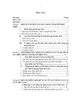
6 Checking methods
6.1 Method A
aA = (n / p) A
Key
1 fixed stop
2 dial gauge
3 movable measuring head
4 datum
5 metering bar
6 checking block
(1)
Figure 2 — Measuring principle of method A
6.2 Method B
The checking loads, F1 and F2, are applied via the measuring head and two metering bars to both parting
line faces of the half bearing (see Figure 3).
4
Copyright International Organization for Standardization
Provided by IHS under license with ISO
No reproduction or networking permitted without license from IHS
© ISO 2012 – All rights reserved
Licensee=University of Alberta/5966844001, User=sharabiani, shahramfs
Not for Resale, 12/02/2013 04:54:36 MST
--``,,,``,,`,```,,,,`,```,```,,,-`-`,,`,,`,`,,`---
The checking load, F, is directly applied via the measuring head with a pivoting metering bar to one parting
line face of the half bearing while the other parting line face is in contact with a fixed stop (see Figure 2).
ISO 3548-3:2012(E)
Key
1 dial gauge
2 datum
3 rigid metering bara
4 checking block
5 pivoting toe piece
a
Bearings may also be checked using two pivoting metering bars.
Figure 3 — Measuring principle of method B
(2)
--``,,,``,,`,```,,,,`,```,```,,,-`-`,,`,,`,`,,`---
aB = aB1 + aB2 = a
NOTE
In the case of method A, the fixed stop exerts the required counterforce, which, in the case of method B,
is applied directly by the measuring equipment via two metering bars.
EXAMPLE
Method A
Method B
F = 6 000 N
F1 = 6 000 N
F2 = 6 000 N
7 Choice and designation of checking method
7.1 Choice of checking method
Recommendations for choosing either method A or method B, based on dimensions of the half bearings
to be checked, are given in Table 3.
© ISO 2012 – All rights reserved
Copyright International Organization for Standardization
Provided by IHS under license with ISO
No reproduction or networking permitted without license from IHS
5
Licensee=University of Alberta/5966844001, User=sharabiani, shahramfs
Not for Resale, 12/02/2013 04:54:36 MST
ISO 3548-3:2012(E)
However, any size of bearing may be tested by either method by agreement between the manufacturer
and user. In that case, a correction, δ, should be applied to compensate for the difference in deflections
at parting line face(s) under load between method A and method B, and be such that:
a A = aB1 + aB2 + δ
(3)
The value of δ shall be determined empirically by actual measurements obtained on the two different
types of equipment used. Since the detailed design of the checking feature shall be varied between
different manufacturers, the value of δ established by one manufacturer cannot be transferred to
another, who shall determine it separately. See example in Annex E.
For general guidance, the value of δ may be derived from the formula used in the mathematical analysis
of belt friction, which gives:
d cb,m ⋅ F
s ms ⋅ B ms
⋅
(
1
1 + e − f π − 2e − f π /2
2Ef
)
(4)
With a value of the friction coefficient f = 0,15, Formula (4) becomes:
δ x = 7 ⋅ 10 −7 ⋅
d cb,m ⋅ F
(5)
s ms ⋅ B ms
(See also 16.5.)
Table 3 — Selection of checking method
Dbs
mm
Dbs ≤ 200
200 < Dbs ≤ 500
7.2 Designation of checking method
Recommended checking method
A, B
B
An example of the designation of method B for checking thin-walled half bearings with an outside
diameter, Dbs of 340 mm is as follows:
Method ISO 3548-3-B-340
8 Measuring equipment
Figures 4 and 5 show typical measuring equipment for the measurement of the crush height by method A
and by method B, respectively.
6
Copyright International Organization for Standardization
Provided by IHS under license with ISO
No reproduction or networking permitted without license from IHS
© ISO 2012 – All rights reserved
Licensee=University of Alberta/5966844001, User=sharabiani, shahramfs
Not for Resale, 12/02/2013 04:54:36 MST
--``,,,``,,`,```,,,,`,```,```,,,-`-`,,`,,`,`,,`---
δ=
--``,,,``,,`,```,,,,`,```,```,,,-`-`,,`,,`,`,,`---
ISO 3548-3:2012(E)
Key
1 checking block
2 pivoting metering bar
3 pressure adjustment valve
4 drive motor
5 oil pump
6 pressure cylinder
7 movable measuring head
8 dial gauge
9 pressure gauge
Figure 4 — Typical measuring equipment with one column, for method A
NOTE
Figures 4
and 5 show hydraulically operated equipment. Pneumatically or mechanically operated
equipment can also be used.
© ISO 2012 – All rights reserved
Copyright International Organization for Standardization
Provided by IHS under license with ISO
No reproduction or networking permitted without license from IHS
7
Licensee=University of Alberta/5966844001, User=sharabiani, shahramfs
Not for Resale, 12/02/2013 04:54:36 MST
ISO 3548-3:2012(E)
--``,,,``,,`,```,,,,`,```,```,,,-`-`,,`,,`,`,,`---
Key
1 rigid metering bara
2 dial gauge
3 movable measuring gauge
4 pressure gauge
5 hydraulic ram
6 pivoting toe piece
7 dial gauge
8 checking block
a
Bearings may also be checked using two pivoting metering bars.
Figure 5 — Typical measuring equipment with two columns, for method B
9 Measuring equipment requirements
9.1 General
The most important factors affecting the accuracy of the measuring equipment (and hence the measured
crush height) are given in the following subclauses.
9.2 Tolerance on checking load setting
The permissible tolerances are given in Table 4.
8
Copyright International Organization for Standardization
Provided by IHS under license with ISO
No reproduction or networking permitted without license from IHS
© ISO 2012 – All rights reserved
Licensee=University of Alberta/5966844001, User=sharabiani, shahramfs
Not for Resale, 12/02/2013 04:54:36 MST
ISO 3548-3:2012(E)
Table 4 — Tolerance ranges for checking loads
F
Tolerance on F
N
±%
F ≤ 2 000
1,25
2 000 < F ≤ 5 000
1,00
5 000 < F ≤ 10 000
0,75
--``,,,``,,`,```,,,,`,```,```,,,-`-`,,`,,`,`,,`---
10 000 < F ≤ 50 000
0,50
50 000 < F
0,25
9.3 Speed of approach of measuring head
The checking load, F, shall be applied to the parting line face(s) of the half bearing so that shock load shall
not occurr. The speed of approach shall be 10 mm/s ± 2 mm/s.
For devices in which the speed of approach cannot be altered, the load shall be applied, released and
applied a second time before the measurement is made.
9.4 Construction of measuring head
The measuring head shall be so designed and manufactured that it is accurately guided and moves
normal to the datum of the checking block. The deviation from parallelism between the metering bar(s)
in the measuring head and the supporting plane of the checking block shall not exceed 0,04 mm per
100 mm in a radial direction.
9.5 Accuracy of the measuring plane for metering bars
Specifications on the accuracy of the measuring plane of the metering bars are given in Table 5.
Table 5 — Tolerances of the measuring plane for metering bars
Dbs
mm
Dbs ≤ 160
160 < Dbs ≤ 340
340 < Dbs ≤ 500
Surface roughness
Ra
Tolerance on flatness
0,2
0,001 5
µm
0,4
9.6 Accuracy of the dial gauge
mm
0,003 0
0,004 0
Uncertainty of measurement u ≤ 1,2 µm (±2σ) with σ = 0,3 µm.
10 Gauging tools for establishing the datum
10.1 General
The following equipment may be used for carrying out measurements:
— a master checking block (for reference measurements) (see Clause 11), or
— a series checking block (for series control in production) (see Clause 11), or
— a master shell (for series control in production) (see Clause 12).
© ISO 2012 – All rights reserved
Copyright International Organization for Standardization
Provided by IHS under license with ISO
No reproduction or networking permitted without license from IHS
Licensee=University of Alberta/5966844001, User=sharabiani, shahramfs
Not for Resale, 12/02/2013 04:54:36 MST
9
ISO 3548-3:2012(E)
It shall be used in three ways (as indicated in 10.2, 10.3 and 10.4) to establish the appropriate datum for
setting the gauge.
10.2 Master checking block (used alone)
The master checking block is the comparison basis for the other checking blocks used for series control.
10.3 Series checking block used alone
The peripheral length of the bore of this type of checking block is determined by comparison with the
master checking block.
lt is applied in series control without using a master shell or a comparison shell.
10.4 Series checking block with master shell
The peripheral length of the checking block bore is determined by the master shell or comparison shell,
the peripheral length of which was determined in the master checking block.
This combination of gauging tools is applied in series control.
NOTE
For series control, a checking block can also be used with a checking master, but this combination of
gauging tools is not within the scope of this part of ISO 3548.
11 Checking block requirements
11.1 General
A typical block is shown in Figure 6. The gauging part has a bore diameter, dcb, and height, Hcb, and holds
the half bearings to be checked.
The checking block should preferably be of hardened steel and of rigid design and manufacturing so that
the requirements of Clause 16 are met when the half bearing is tested under load.
--``,,,``,,`,```,,,,`,```,```,,,-`-`,,`,,`,`,,`---
The bore of the checking block shall not be chromium plated.
Recesses shall be cut into the checking block to accommodate the locating lip in the half bearings. They
shall be 1 mm wider and deeper and 1,5 mm longer than the locating lips in the half bearings.
10
Copyright International Organization for Standardization
Provided by IHS under license with ISO
No reproduction or networking permitted without license from IHS
© ISO 2012 – All rights reserved
Licensee=University of Alberta/5966844001, User=sharabiani, shahramfs
Not for Resale, 12/02/2013 04:54:36 MST
ISO 3548-3:2012(E)
11.2 Reference tooling: master checking block — General
--``,,,``,,`,```,,,,`,```,```,,,-`-`,,`,,`,`,,`---
11.2.1 Reference tooling — Master checking block
Key
1 datum for Fcor,cb and Fcor,cbs (see 13.1 and 13.2.1)
2 field for marking of dcb,M, Hcb,M and Fcor,cb (or Fcor,cbs)
3 ejector hole (optional)
a
It is recommended that the values given in Table 5 and 6 be observed.
b
Construction for half bearing without flange:
B1 may correspond to B2 or it may be adjusted to the width of the half bearing,
i.e. to Bmax + 1,2mm with K1,max = 0,4 mm
c
Construction for flanged half bearing:
B1; see Table 5;
K2 = hmax + 0,5 mm.
d
K1 or K2.
Figure 6 — Checking block
11.2.2 Manufacturing limits — General
11.2.2.1 Manufacturing limits
Manufacturing limits and specifications for the master checking block are given in Table 6.
© ISO 2012 – All rights reserved
Copyright International Organization for Standardization
Provided by IHS under license with ISO
No reproduction or networking permitted without license from IHS
11
Licensee=University of Alberta/5966844001, User=sharabiani, shahramfs
Not for Resale, 12/02/2013 04:54:36 MST
ISO 3548-3:2012(E)
Table 6 — Manufacturing limits and specifications for the master checking block
mm
Tolerance on Surface roughness of Tolerance on Surface roughness of
dcbm
checking block bore
Hcbm
the datum face
Ra
Ra
mm
µm
mm
µm
+0,0030
0
Dbs ≤ 75
75 < Dbs ≤ 110
+0,0040
0
0,2
160 < Dbs ≤ 250
+0,0060
0
0,4
340 < Dbs ≤ 500
+0,0100
0
+0,0050
0
110 < Dbs ≤ 160
+0,0075
0
250 < Dbs ≤ 340
+0,0030
0
+0,0035
0
0,3
+0,0045
0
0,6
+0,0040
0
+0,0050
0
0,6
1,0
+0,0060
0
11.2.2.2 Tolerances of form and orientation
lt is the responsibility of the manufacturer of the master checking block to achieve high quality regarding
tolerances of form and orientation, the values of which are given in Tables 7 and 8.
Table 7 — Tolerances of form and orientation — No. 1
Outside
diameter
Dbs
mm
Dbs ≤ 75
75 < Dbs ≤ 110
110 < Dbs ≤ 160
160 < Dbs ≤ 250
250 < Dbs ≤ 340
Bearing
without
flange
B3min
mm
Bmax + 0,4
340 < Dbs ≤ 500
12
Copyright International Organization for Standardization
Provided by IHS under license with ISO
No reproduction or networking permitted without license from IHS
Flanged
bearing
mm
B1,min
zmin 0,1
B1,max
zmin 0,05
Surface
roughness
Ra1
µm
1,2
Tolerances
of form and orientation
t1
t2
t3
mm
t4
t5
t6
0,002 0,002 0,002 0,002 0,002 0,005
0,005
0,007
0,005
0,005
0,007
0,004 0,003 0,006
© ISO 2012 – All rights reserved
Licensee=University of Alberta/5966844001, User=sharabiani, shahramfs
Not for Resale, 12/02/2013 04:54:36 MST
--``,,,``,,`,```,,,,`,```,```,,,-`-`,,`,,`,`,,`---
Outside diameter
Dbs
ISO 3548-3:2012(E)
Table 8 — Tolerances of form and orientation — No. 2
B
B2
mm
mm
80 < B
µm
60 +2
B ≤ 55
55 < B ≤ 80
Surface roughness
Ra2
0
85 +2
Tolerance
on parallelism
t7
1,2
0
B + 5 +02
mm
0,002
0,003
0,004
11.2.2.3 Surface roughnesses Ra1 and Ra2
See Tables 7 and 8.
11.2.2.4 Specifications for B1, B2 and B3
See Tables 7 and 8.
11.2.3 Measuring accuracy of equipment used for establishing dcbm,M and Hcbm,M
Determination of dcbm,M and Hcbm,M shall be carried out using measuring equipment with a tolerance of:
±0,001 mm for dcbm ≤ 160 mm;
±0,002 mm for dcbm > 160 mm.
These values are necessary for calculating the correction factor, Fcor,cbm (see 13.1), which is based on the
peripheral length, determined from Formula (6):
l cbm,M = d cbm,M ⋅
d
π
+ 2 ⋅ H cbm,M − cbm,M
2
2
(6)
11.2.4 Permissible wear limit
The tolerance specified in 11.2.2 for the master checking block shall not be exceeded through wear. If
wear occurs within the specified tolerance range, it may be necessary to change the correction factor.
11.3 Series gauging tools
11.3.1 Series checking block used alone
Since the peripheral length of this checking block bore is determined by comparison with the master
checking block (11.2), larger tolerances for dcbs and Hcbs are acceptable.
11.3.2 Manufacturing limits, correction factor and permissible wear limit
11.3.2.1 Manufacturing limits
Manufacturing limits and specifications for the series checking block are given in Tables 9 to 11.
--``,,,``,,`,```,,,,`,```,```,,,-`-`,,`,,`,`,,`---
© ISO 2012 – All rights reserved
Copyright International Organization for Standardization
Provided by IHS under license with ISO
No reproduction or networking permitted without license from IHS
13
Licensee=University of Alberta/5966844001, User=sharabiani, shahramfs
Not for Resale, 12/02/2013 04:54:36 MST
ISO 3548-3:2012(E)
Table 9 — Manufacturing limits and specifications for the series checking block — No. 1
Outside diameter
Dbs
mm
Tolerance on Surface roughness of Tolerance on Surface roughness of
dcbs
checking block bore
Hcbs
the datum
Ra
Ra
mm
µm
+0,010
0
0,2
+0,014
0
0,4
Dbs ≤ 75
+0,008
0
110 < Dbs ≤ 160
+0,012
0
250 < Dbs ≤ 340
+0,017
0
75 < Dbs ≤ 110
160 < Dbs ≤ 250
340 < Dbs ≤ 500
µm
+0,009
0
0,3
+0,010
0
0,6
+0,008
0
+0,010
0
+0,011
0
0,6
+0,022
0
mm
1,0
+0,012
0
Table 10 — Manufacturing limits and specifications for the series checking block — No. 2
Outside
diameter
Dbs
mm
Dbs ≤ 75
75 < Dbs ≤ 110
110 < Dbs ≤ 160
160 < Dbs ≤ 250
250 < Dbs ≤ 340
Bearing
without
flange
B3min
Flanged
bearing
mm
mm
B1,min
zmin 0,1
Bmax + 0,4
340 < Dbs ≤ 500
B1,max
zmin 0,05
Surface
roughness
Ra1
Tolerances
of form and orientation
µm
1,2
t1
t2
t3
mm
t4
t5
t6
0,004 0,004 0,004 0,004 0,004 0,010
0,010
0,014
0,010
0,010
0,014
0,008 0,006 0,012
Table 11 — Manufacturing limits and specifications for the series checking block — No. 3
B
B2
mm
mm
60 +2
B ≤ 55
55 < B ≤ 80
80 < B
14
0
85 +2
0
B + 5 +2 5 0+2
--``,,,``,,`,```,,,,`,```,```,,,-`-`,,`,,`,`,,`---
Copyright International Organization for Standardization
Provided by IHS under license with ISO
No reproduction or networking permitted without license from IHS
0
Surface roughness
Ra2
àm
1,2
Tolerance
on parallelism
t7
mm
0,004
0,006
0,008
â ISO 2012 – All rights reserved
Licensee=University of Alberta/5966844001, User=sharabiani, shahramfs
Not for Resale, 12/02/2013 04:54:36 MST