Tiêu chuẩn iso 00489 1999
Bạn đang xem bản rút gọn của tài liệu. Xem và tải ngay bản đầy đủ của tài liệu tại đây (82.12 KB, 16 trang )
INTERNATIONAL
STANDARD
ISO
489
Second edition
1999-04-15
--`,,```,,,,````-`-`,,`,,`,`,,`---
Plastics — Determination of refractive index
Plastiques — Détermination de l'indice de réfraction
A
Copyright International Organization for Standardization
Provided by IHS under license with ISO
No reproduction or networking permitted without license from IHS
Reference number
ISO 489:1999(E)
Not for Resale
ISO 489:1999(E)
Contents
Page
1 Scope ........................................................................................................................................................................ 1
2 Normative references .............................................................................................................................................. 1
3 Apparatus and materials ......................................................................................................................................... 2
3.1 Method A................................................................................................................................................................ 2
3.2 Method B................................................................................................................................................................ 3
4 Preparation of test specimens ............................................................................................................................... 3
4.1 Method A................................................................................................................................................................ 3
4.2 Method B................................................................................................................................................................ 4
4.3 Required number of specimens or measurements ........................................................................................... 4
5 Conditioning............................................................................................................................................................. 4
6 Procedure ................................................................................................................................................................. 4
6.1 Method A................................................................................................................................................................ 4
6.2 Method B................................................................................................................................................................ 8
7 Precision................................................................................................................................................................... 9
8 Test report .............................................................................................................................................................. 10
© ISO 1999
All rights reserved. Unless otherwise specified, no part of this publication may be reproduced or utilized in any form or by any means, electronic
or mechanical, including photocopying and microfilm, without permission in writing from the publisher.
International Organization for Standardization
Case postale 56 • CH-1211 Genève 20 • Switzerland
Internet
Printed in Switzerland
--`,,```,,,,````-`-`,,`,,`,`,,`---
ii
Copyright International
Organization for Standardization
Provided by IHS under license with ISO
No reproduction or networking permitted without license from IHS
Not for Resale
©
ISO
ISO 489:1999(E)
Foreword
ISO (the International Organization for Standardization) is a worldwide federation of national standards bodies (ISO
member bodies). The work of preparing International Standards is normally carried out through ISO technical
committees. Each member body interested in a subject for which a technical committee has been established has
the right to be represented on that committee. International organizations, governmental and non-governmental, in
liaison with ISO, also take part in the work. ISO collaborates closely with the International Electrotechnical
Commission (IEC) on all matters of electrotechnical standardization.
International Standards are drafted in accordance with the rules given in the ISO/IEC Directives, Part 3.
Draft International Standards adopted by the technical committees are circulated to the member bodies for voting.
Publication as an International Standard requires approval by at least 75 % of the member bodies casting a vote.
International Standard ISO 489 was prepared by Technical Committee ISO/TC 61, Plastics, Subcommittee SC 5,
Physical-chemical properties.
--`,,```,,,,````-`-`,,`,,`,`,,`---
This second edition cancels and replaces the first edition (ISO 489:1983), of which it constitutes a technical revision.
Copyright International Organization for Standardization
Provided by IHS under license with ISO
No reproduction or networking permitted without license from IHS
iii
Not for Resale
--`,,```,,,,````-`-`,,`,,`,`,,`---
Copyright International Organization for Standardization
Provided by IHS under license with ISO
No reproduction or networking permitted without license from IHS
Not for Resale
INTERNATIONAL STANDARD
©
ISO 489:1999(E)
ISO
Plastics — Determination of refractive index
1 Scope
This International Standard specifies two test methods for determining the refractive index of plastics, namely:
Method A: a refractometric method for measuring the refractive index of moulded parts, cast or extruded sheet
or film, by means of a refractometer. It is applicable not only to isotropic transparent, translucent, coloured or
opaque materials but also to anisotropic materials. The method is recommended when great accuracy is
required. It is not applicable to powdered or granulated material.
Method B: an immersion method (making use of the Becke line phenomenon) for determining the refractive
index of powdered or granulated transparent materials by means of a microscope. Monochromatic light should,
in general, be used to avoid dispersion effects. The accuracy of this method is about the same as that of
method A. It is applicable to isotropic translucent, coloured materials but is not applicable to opaque materials
nor to anisotropic materials.
--`,,```,,,,````-`-`,,`,,`,`,,`---
NOTE 1 The refractive index is a fundamental property which can be used for checking purity and composition, for the
identification of materials and for the design of optical parts. The change in refractive index with temperature may give an
indication of transition points of materials.
NOTE 2 The accuracy of method B is approximately the same as that of method A when an experienced operator uses the
method with extreme care (see clause 7).
2 Normative references
The following normative documents contain provisions which, through reference in this text, constitute provisions of this
International Standard. For dated references, subsequent amendments to, or revisions of, any of these publications do
not apply. However, parties to agreements based on this International Standard are encouraged to investigate the
possibility of applying the most recent editions of the normative documents indicated below. For undated references,
the latest edition of the normative document referred to applies. Members of ISO and IEC maintain registers of
currently valid International Standards.
ISO 291:1997, Plastics — Standard atmospheres for conditioning and testing.
ISO 5725-1:1994, Accuracy (trueness and precision) of measurement methods and results — Part 1: General
principles and definitions.
ISO 5725-2:1994, Accuracy (trueness and precision) of measurement methods and results — Part 2: Basic method
for the determination of repeatability and reproducibility of a standard measurement method.
ISO 5725-3:1994, Accuracy (trueness and precision) of measurement methods and results — Part 3: Intermediate
measures of the precision of a standard measurement method.
Copyright International Organization for Standardization
Provided by IHS under license with ISO
No reproduction or networking permitted without license from IHS
1
Not for Resale
ISO 489:1999(E)
©
ISO
3 Apparatus and materials
3.1 Method A
3.1.1 Abbe refractometer, or any other refractometer that can be shown to give the same results, accurate to
0,001 and capable of measuring the refractive index in the range from 1,300 to 1,700. A temperature-controlling
device (3.1.4) shall be provided for the specimens and prisms.
3.1.2 White or sodium lamp, used as a source of light.
3.1.3 Contacting liquid.
WARNING — The contacting liquid may present an environmental hazard during handling, storage and
disposal. Verify its toxicity and follow national and regional regulations for safe handling and disposal.
The contacting liquid shall have a refractive index higher than that of the material to be examined and shall not
soften, attack or dissolve the plastic material. The liquids listed in Table 1 may be used for the respective plastic
materials, but other liquids meeting these requirements may also be used.
Table 1 — Contacting liquids
Plastic material
Contacting liquid
--`,,```,,,,````-`-`,,`,,`,`,,`---
Cellulose derivatives
Aniseed oil or 1-bromonaphthalene
Fluorine-containing polymers
1-Bromonaphthalene
Urea-formaldehyde
Aniseed oil or 1-bromonaphthalene
Phenol-formaldehyde
1-Bromonaphthalene
Polyethylenes
1-Bromonaphthalene
Polyamides
1-Bromonaphthalene
Unsaturated polyester
1-Bromonaphthalene
Polyisobutylene
Saturated aqueous solution of zinc chloride made slightly acid
Poly(methyl methacrylate)
Saturated aqueous solution of zinc chloride made slightly acid
or 1-bromonaphthalene
Polystyrene
Saturated potassium mercury(II) iodide solution
Styrene-acrylonitrile copolymers
1-Bromonaphthalene
Vinyl resins (vinyl chloride copolymer
or plasticized PVC)
1-Bromonaphthalene
Poly(vinyl chloride)
1-Bromonaphthalene
Poly(ethylene terephthalate)
Methylene iodide
Polycarbonate
Methylene iodide
Diethylene glycol bis(allyl carbonate)
(CR 39)
Methyl salicylate, aniseed oil or 1-bromonaphthalene
Polyarylate
Saturated aqueous solution of zinc chloride made slightly acid,
methylene iodide or 1-bromonaphthalene
Polyetheretherketone
Methylene iodide
Polypropylene
1-Bromonaphthalene
2
Copyright International Organization for Standardization
Provided by IHS under license with ISO
No reproduction or networking permitted without license from IHS
Not for Resale
©
ISO
ISO 489:1999(E)
3.1.4 Temperature-controlled water bath, capable of maintaining the temperature at (23 ± 0,5) °C for the main
prism, sub-prism and the specimen.
NOTE
The circulating water should be distilled water.
3.2 Method B
3.2.1 Microscope, having a magnifying power of at least ¥ 200, an objective giving approximately ¥ 20 of primary
magnification and a substage condenser fitted with a centering illuminating-aperture diaphragm capable of being
stopped down to give a very narrow axial beam.
3.2.2 Monochromatic light, usually the sodium D line, having a wavelength of 589 nm, is used as the light source
for the microscope.
3.2.3 Immersion liquids, with different refractive indices.
WARNING — The contacting liquid may present an environmental hazard during handling, storage and
disposal. Verify its toxicity and follow national and regional regulations for safe handling and disposal.
The immersion liquids listed in Table 2 with known refractive indices can be used separately and also as mixtures
when different increments of accuracy are needed (for example, a difference of 0,002 to within ± 0,001). The
immersion liquids shall not soften, attack, dissolve or swell the surface of the particles.
Table 2 — Immersion liquids
Immersion liquid
Refractive index at 23 °C
n-Butyl carbonate
1,410
Tri-n-butyl citrate
1,444
n-Butyl phthalate
1,491
1-Bromonaphthalene
1,657
Diiodomethane (methylene iodide)
1,747
Aqueous solution of potassium mercury(II) iodide
1,419 to 1,733a
Silicone oils
1,37 to 1,56a
a
--`,,```,,,,````-`-`,,`,,`,`,,`---
nD23
Useful range for the purpose of the test.
4 Preparation of test specimens
4.1 Method A
Cut, from the sample, specimens of such a size as to fit on the face of the fixed half of the refractometer prisms.
The following dimensions are recommended for sheet specimens:
width:
8 mm
length:
20 mm
thickness: 3 mm to 5 mm
For maximum accuracy, the surface of the test specimen in contact with the prism (the measurement face) shall be
optically flat and well-polished. Eliminate any burs formed by cutting or any contamination attached to the specimen.
Copyright International Organization for Standardization
Provided by IHS under license with ISO
No reproduction or networking permitted without license from IHS
3
Not for Resale
ISO 489:1999(E)
©
ISO
Satisfactory contact between the specimen and the prism is indicated when the dividing line between the light and
dark halves of the eyepiece field appears sharp and straight.
Ensure that the edge of the specimen (perpendicular to the first) is also optically flat and fairly well-polished. The
two polished surfaces shall intersect along a sharp line without a bevelled or rounded edge.
The following dimensions are recommended for film specimens:
width:
8 mm
length:
20 mm
thickness: the actual film thickness, but not less than 2 µm
For anisotropic material, see 6.1.3.
4.2 Method B
The test sample consists of particles of the material to be examined, for example powder, granules or chips. The
particles shall have dimensions sufficiently small and be so distributed as to permit simultaneous observation of
approximately equal areas of the sample and the surrounding area in the field of view.
Ensure that the thickness of the test sample is significantly lower than the working distance of the microscope
objective.
4.3 Required number of specimens or measurements
For sheets or films, five specimens are required. In the case of powders, pellets and granules, a quantity of sample
sufficient to make five measurements is required.
5 Conditioning
5.1 Condition the specimens in accordance with ISO 291 at (23 ± 2) °C and at (50 ± 5) % relative humidity for not
less than 88 h prior to the test if no other period of conditioning is stated in the relevant material specification.
5.2 Set up the test apparatus in an atmosphere maintained at (23 ± 2) °C and (50 ± 5) % relative humidity.
6 Procedure
6.1 Method A
If an Abbe refractometer (3.1.1) is used, carry out the following procedure. For other refractometers, modify the
procedure in accordance with the manufacturer’s recommendations, if necessary.
Carry out the determination at (23 ± 0,5) °C.
--`,,```,,,,````-`-`,,`,,`,`,,`---
6.1.1 Transparent sheet
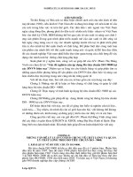
Place a small drop of the contacting liquid (3.1.3) on the well-polished surface of the transparent sheet specimen
(the measurement face) and place it in firm contact with the surface of the prism with the polished edge of the
specimen towards the light source as shown in Figure 1. Adjust the index arm of the refractometer until half of the
eyepiece field is dark.
Adjust the compensator (Amici prisms) drum until all colours have been removed from the field. Then adjust the
index arm by means of the vernier until the dividing line between the light and dark portions of the field coincides
exactly with the point of intersection of the eyepiece cross-hairs as shown in Figure 2.
4
Copyright International Organization for Standardization
Provided by IHS under license with ISO
No reproduction or networking permitted without license from IHS
Not for Resale
©
ISO
ISO 489:1999(E)
Read the refractive index of the material from the instrument scale.
Key
1
Compensator drum
4
Specimen
7
Opal-coloured reflective plate
2
Index arm
5
Contacting liquid
8
Sub-prism
3
Eyepiece
6
Source of light
9
Main prism
--`,,```,,,,````-`-`,,`,,`,`,,`---
The dispersion, if required, can be found by noting the compensator drum reading and using this, together with the
value of the refractive index, to read the dispersion from a chart supplied with the instrument.
Figure 1 — Method for measuring refractive index of transparent sheet
Key
1
Boundary line
4
Dark half of eyepiece field
2
Cross-hair lines
5
Scale for refractive index
3
Light half of eyepiece field
Figure 2 — Refractometer field of vision
Copyright International Organization for Standardization
Provided by IHS under license with ISO
No reproduction or networking permitted without license from IHS
5
Not for Resale
ISO 489:1999(E)
©
ISO
6.1.2 Film
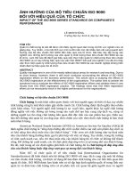
Place a drop of the contacting liquid (3.1.3) on the main prism followed by a film specimen. Place another drop of
contacting liquid on the top of the film and then place the glass plate on the specimen as shown in Figure 3. The
refractive index of the glass plate shall be greater than that of the film specimen.
Use the sodium lamp illuminator for the measurements of anistropic film such as oriented ones so as to obtain a
beam of steady incident light and to avoid any dispersion effects. As shown in Figure 1, open the sub-prism and
place the opal-coloured reflective plate against it to reflect the light of the sodium lamp onto the edge of the glass
plate.
NOTE
It is difficult to measure the refractive index of film specimens because films are very thin and this results in a limited
amount of incident light passing through the edge of the specimen. To compensate for this, place a glass plate on top of the
specimen.
Key
1
Glass plate
2
Contacting liquid
3
Main prism
4
Film specimen
5
Light
Figure 3 — Method for measuring refractive index of film
6.1.3 Anisotropic material
In the case of anisotropic material such as injection or extrusion mouldings, different values of the refractive index
may be found when measurements are made in different parts of the specimen (Figure 4). In such cases, different
specimens are prepared with their polished edges parallel or perpendicular to the machine direction.
By attaching a polarizing filter to the eyepiece of the Abbe refractometer, the measurement of specimens with
multiple refractive indices can be made. By using different combinations of the specimen-positioning direction
(illuminated surface facing the machine direction or at 90° from the machine direction) and of the polarizing-filter
direction (rotating the filter 90° between two positions) as shown in Figure 5, the refractive index can be measured
in any particular direction.
6
--`,,```,,,,````-`-`,,`,,`,`,,`---
Copyright International Organization for Standardization
Provided by IHS under license with ISO
No reproduction or networking permitted without license from IHS
Not for Resale
©
ISO
ISO 489:1999(E)
Key
X At right angle to the machine direction
Y Machine direction
Z Thickness
Figure 4 — Film with multiple refractive indices
Measurement
direction
Thickness
Thickness
Machine direction
(Z axis)
At right angle to
machine direction
(X axis)
(Z axis)
(Y axis)
Light
Light
Light
Light
Positioning of
specimen with
multiple refractive
indices (machine
direction indicated by
arrows)
Polarizing direction
(indicated by arrows)
Figure 5 — Combination of specimen-positioning direction and polarizing-filter direction
6.1.4 Translucent, coloured and opaque material
For translucent, coloured and opaque materials, the reflection mode of the Abbe refractometer shall be used. In this
mode, the light enters the prism through an upper window and reflects at the interface between the prism and the
specimen as shown in Figure 6.
NOTE In cases of translucent, coloured or opaque material, it is difficult to measure the refractive index by the transmission
method because of a lack of reflected light. In such cases, it is possible to measure refractive indices by the reflection mode.
When the reflection mode is used, the bright field and the dark field are inverted, and their contrast becomes poor.
7
--`,,```,,,,````-`-`,,`,,`,`,,`---
Copyright International Organization for Standardization
Provided by IHS under license with ISO
No reproduction or networking permitted without license from IHS
Not for Resale
ISO 489:1999(E)
©
ISO
1
Compensator drum
5
Contacting liquid
2
Index arm
6
Window for lighting
3
Eyepiece
7
Light
4
Specimen
8
Main prism
Figure 6 — Method for measuring refractive index of translucent, coloured and opaque materials
6.2 Method B
Carry out the following determination at (23 ± 0,5) °C.
Place a small amount of an immersion liquid (3.2.3) on a slide. The immersion liquid shall be of a known refractive
index (see Table 2) which is close to that of the material under test.
If the refractive index of the material to be examined is unknown, it is recommended that an immersion liquid with a
refractive index of about 1,56 be used.
Place some particles of the material to be examined into the liquid on the slide and add a cover slip. Align the
condenser and stop it down to give a narrow beam of axial illumination.
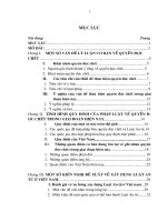
Place the sample preparation on the microscope stage and focus on the particles. Slightly defocus by increasing the
separation between the microscope objective and the sample preparation. The Becke line, seen as a bright halo
around or within the particle, will move towards the medium having the higher refractive index as shown in Figure 7.
Repeat the test with preparations in other immersion liquids with a known refractive index and particles of the
material to be examined until a match is found, or until the index of the test sample is found to be between two
known indices in the series of liquid standards. The Becke line phenomenon does not appear when the microscope
objective is raised or lowered if the refractive index of the material to be examined is equal to the refractive index of
the immersion liquid used for the determination test.
Any bubbles which appear during the preparation are useful for checking the focus when the match of the sample
and the immersion liquid is close.
8
Copyright International Organization for Standardization
Provided by IHS under license with ISO
No reproduction or networking permitted without license from IHS
Not for Resale
--`,,```,,,,````-`-`,,`,,`,`,,`---
Key
©
ISO
ISO 489:1999(E)
Key
1
Becke line
2
Lift the lens-barrel of the microscope to defocus slightly
3
Where the immersion liquid has a higher refractive index than that of the sample, the Becke line is seen moving towards
the immersion liquid
4
In the opposite case, the Becke line is seen moving towards the particle
Figure 7 — Becke line and its movement
7 Precision
An international trial involving eight laboratories was conducted in 1996 to determine the precision of the two
methods. Measurements were made on eleven samples for method A and six samples for method B, among which
three samples were of the same materials. The data were analysed in accordance with ISO 5725-1, ISO 5725-2
and ISO 5725-3. The results are shown in Table 3. No outliers were detected by Grubb’s test.
The anisotropic specimens were carefully selected and their orientation direction was identified for the series of
measurements performed using method A.
Reproducibility means precision under conditions where test results are obtained with the same method on identical
test material in different laboratories with different operators using different equipment and expressed in terms of
reproducibility standard deviation.
NOTE 1 In method A, PMMA cast sheet and fully shrunk and annealed PMMA cast sheet, which would be expected to have
little orientation and optical stress, give a reproducibility standard deviation of less than 0,000 4. Others range from 0,000 7 to
0,008 depending on the scattering of the data due to local differences within the samples. In the case of the fully shrunk and
annealed PMMA cast sheet, the reproducibility standard deviation is slightly smaller than that calculated from the data from the
within-laboratory tests. A possible interpretation is that the values of reproducibility were inverted for this particular material
because sR can only be greater than or equal to sRw. Nonetheless, the precision of this method is very high for this material and
the difference between sR and sRw is only 0,000 1 which corresponds to the detection limit of the method.
NOTE 2 In general, method B for granules gives worse reproducibility than method A. This is clearly shown by the data
generated for sheet and granulated samples from the same material: for PMMA (2, 15) and PS (6,17).
Copyright International Organization for Standardization
Provided by IHS under license with ISO
No reproduction or networking permitted without license from IHS
9
Not for Resale
--`,,```,,,,````-`-`,,`,,`,`,,`---
Reproducibility-within-laboratory means precision under conditions where test results are obtained with the same
method on identical material in the same laboratory, and the operator, the equipment and the time of measurement
are either partly or totally different.
ISO 489:1999(E)
©
ISO
Table 3 — Interlaboratory trial data
No.
Method
Plastic material
Average refractive
index
Within-laboratory
reproducibility
standard deviation
Reproducibility
standard deviation
nD23
sRw
sR
1
A
PMMA cast sheet
1,491 1
0,000 36
0,000 41
2
A
PMMA shrunk and annealed
cast sheet
1,491 4
0,000 58
0,000 46
3
A
PC extruded sheet
(machine direction)
1,583 9
0,000 40
0,000 82
4
A
PC extruded sheet
(transversal direction)
1,583 7
0,000 65
0,000 67
5
A
High-RI resin castings for
spectacle lenses
1,657 9
0,000 20
0,001 02
6
A
PS pressed sheet
1,590 8
0,000 54
0,000 71
7
A
Cyclic-olefin copolymer
1,542 8
0,006 58
0,007 31
8
A
PP film (machine direction)
1,504 6
0,000 54
0,008 32
9
A
PP film (transversal direction)
1,504 1
0,000 37
0,000 46
10
A
FEP film (machine direction)
1,344 7
0,001 13
0,001 52
11
A
FEP film (transversal direction)
1,343 4
0,000 39
0,001 13
12
B
PMMA beads as polymerized
1,490 6
0,000 37
0,000 51
13
B
PC powder as polymerized
1,584 7
0,000 31
0,005 45
14
B
Cyclic-olefin copolymer
(granulated)
1,541 7
0,000 33
0,002 53
15
B
PMMA shrunk and annealed
(granulated)
1,490 9
0,000 34
0,000 92
16
B
PC (granulated)
1,582 5
0,000 42
0,003 04
17
B
PS (granulated)
1,591 9
0,000 52
0,004 69
8 Test report
The test report shall include the following information:
a)
a reference to this International Standard;
b)
all details necessary for the complete identification of the material under test;
c)
the method used (A or B);
d)
the type of light source and the wavelength used;
10
Copyright International Organization for Standardization
Provided by IHS under license with ISO
No reproduction or networking permitted without license from IHS
--`,,```,,,,````-`-`,,`,,`,`,,`---
Not for Resale
©
ISO
ISO 489:1999(E)
e)
the position in the original sample from which the specimen was cut (for method A only);
f)
the dispersion, if measured (for method A only);
g)
the refractive index to the nearest significant figure warranted by the precision of the measurements (to more
than three significant figures if the refractive index is expressed using method A);
h)
any deviation, by agreement or otherwise, from the method specified;
i)
the date of measurement.
--`,,```,,,,````-`-`,,`,,`,`,,`---
Copyright International Organization for Standardization
Provided by IHS under license with ISO
No reproduction or networking permitted without license from IHS
11
Not for Resale
ISO 489:1999(E)
©
--`,,```,,,,````-`-`,,`,,`,`,,`---
ICS 83.080.01
Price based on 11 pages
Copyright International Organization for Standardization
Provided by IHS under license with ISO
No reproduction or networking permitted without license from IHS
Not for Resale
ISO