the lit interior
Bạn đang xem bản rút gọn của tài liệu. Xem và tải ngay bản đầy đủ của tài liệu tại đây (5.99 MB, 159 trang )
The Lit Interior
This Page Intentionally Left Blank
William J. Fielder PE, m. IESNA
With contributions by
Frederick H. Jones PhD
The Lit Interior
OXFORD AUCKLAND BOSTON JOHANNESBURG MELBOURNE NEW DELHI
Architectural Press
An imprint of Butterworth-Heinemann
Linacre House, Jordan Hill, Oxford OX2 8DP
225 Wildwood Avenue, Woburn, MA 01801-2041
A division of Reed Educational and Professional Publishing Ltd
A member of the Reed Elsevier plc group
First published 2001
© William J. Fielder and Frederick H. Jones 2001
All rights reserved. No part of this publication may be reproduced in
any material form (including photocopying or storing in any medium by
electronic means and whether or not transiently or incidentally to some
other use of this publication) without the written permission of the
copyright holder except in accordance with the provisions of the Copyright,
Designs and Patents Act 1988 or under the terms of a licence issued by the
Copyright Licensing Agency Ltd, 90 Tottenham Court Road, London,
England W1P 0LP. Applications for the copyright holder’s written
permission to reproduce any part of this publication should be addressed
to the publishers
British Library Cataloguing in Publication Data
Fielder, William J.
The lit interior
1. Interior lighting 2. Lighting, architectural and decorative
I. Title II. Jones, Frederick H. (Frederick Hicks), 1944–
747.9'2
Library of Congress Cataloguing in Publication Data
Fielder, William J.
The lit interior/William J. Fielder; with contributions by Frederick H. Jones.
p. cm.
Includes index.
ISBN 0-7506-4890-2
1. Interior lighting. 2. Electric lighting. 3. Lighting, architectural and
decorative. I. Jones, Frederick H. (Frederick Hicks), 1944–
TH7703.F54 2001
621.32'2–dc21 2001053540
ISBN 0 7506 4890 2
Composition by Scribe Design, Gillingham, Kent, UK
Printed and bound in Great Britain by MPG Books Ltd, Bodmin, Cornwall
Preface ix
Chapter 1. The design medium 1
The process of vision 1
Light mechanics 4
Transmission 5
Refraction 6
Reflection 6
Absorption 7
Physical factors 8
Size 8
Contrast 8
Luminance 8
Time 8
Light quantity 9
Light quality 11
Glare 11
Brightness ratio 12
Diffusion 12
Color rendition 12
The psychology of lighting 13
Summary 16
Exercises 17
Chapter 2. The design tools 19
Lamps – the light source 19
Lamp theory 19
Incandescence 20
Photoluminance 20
Color temperature 22
Color rendering index 23
Contents
Lamp – major types 24
Incandescent lamps 24
Standard incandescent lamps 24
Tungsten halogen lamps 26
Infrared reflecting lamps 27
Incandescent lamp benefits 27
Incandescent lamp drawbacks 27
Incandescent lamp uses 28
Fluorescent lamps 28
Rapid start fluorescent lamps 29
Instant start fluorescent lamps 29
High output and very high output fluorescent lamps 30
Compact fluorescent lamps 30
Other fluorescent lamps 30
Fluorescent lamp advantages 31
Fluorescent lamp drawbacks 31
Fluorescent lamp uses 31
High intensity discharge (HID) lamps 32
Mercury vapor lamps 34
Metal halide lamps 35
High pressure sodium lamps 37
Low pressure sodium lamps 39
Ballasts 40
Fluorescent ballasts 40
Magnetic fluorescent ballasts 40
Hybrid fluorescent ballasts 40
Electronic fluorescent ballasts 40
High intensity discharge (HID) ballasts 41
Reactor ballast 41
High reactance autotransformer ballast 42
Constant wattage 42
Constant wattage autotransformer ballast 42
Luminaires 43
Reflectors 43
Shielding and diffusion devices 44
Baffles 45
Diffusers 45
Luminaire housings 46
Luminaire classification 46
Direct illumination 46
Semi-direct illumination 48
Semi-indirect and indirect illumination 48
Luminaire photometric data 49
Lighting calculations 49
vi Contents
Zonal cavity calculations 50
Computerized calculations 55
Controls 58
Standards, codes, and design guidelines 58
NFPA-70, The National Electric Code 59
NFPA-101, The Life Safety Code 59
ASHRAE/IES Standard 90.1 59
EPACT 92 62
IES recommended illumination levels 63
Exercises 65
Chapter 3. The design process 67
Ambient lighting 68
Luminaire selection 68
Energy code compliance 80
Task lighting 82
Luminaire selection 83
Accent lighting 87
Lighting for life safety 90
Exercises 93
Chapter 4. Powering and controlling the system 94
Power 94
System voltage 94
Wire sizing 95
Panelboards 95
Load calculations 98
Wiring and raceways 98
Lighting controls 100
Switches 100
Dimmers 102
Contactors 103
Photocells 104
Timers 104
Occupancy sensors 105
Light-sensitive controls 106
Example 106
Exercises 110
Chapter 5. The contract documents 111
The project plans 113
Project specifications 116
Section 16510 – Interior lighting 118
Part 1. General 118
Contents vii
Part 2. Products 120
Part 3. Execution 124
Exercises 125
Chapter 6. The second time around – retrofitting 127
The problem 127
The solution 128
Improving luminaire optics 128
Upgrading the ballast 129
Upgrading the lamps 129
Glossary 134
Index 145
viii Contents
This book is intended as a design guide for those individuals in
the fields of electrical engineering, architecture, and interior
design who will one day design lighting systems for others to
build.
The book is organized so that an individual with little or no
training in lighting design will become familiar with the basic
principles and psychology behind good lighting before design proce-
dures are addressed. Discussions on the process of vision and the
properties of light set the stage for exploring the various tools at
the designer’s disposal for creating and manipulating light to
provide a desired effect in an architectural space.
The reader is then led through the conceptual design process,
which entails the use of manufacturer’s offerings, codes and guide-
lines for space lighting, as well as calculation methods to predict
the performance of a design. The conceptual design is rounded out
by exploring methods for powering and controlling a lighting
system.
A realistic design problem is begun early in the journey, and is
completed, bit-by-bit, as each new concept is explored and applied
to the design. Documentation of the design is the final stage of the
process, which culminates in a finished set of plans and detailed
specifications for the project. A final segment of the book, called
‘The Second Time Around’, is devoted to retrofitting existing ineffi-
cient lighting systems with new, energy-efficient components to
improve light quality and reduce the energy consumption of older
systems.
Extensive use of the Internet is used throughout the design
process. Instructions for downloading and using manufacturer’s
data, calculation engines, and other tools are included in the text
and put to use in the exercises. In the interest of continuity, Inter-
net information for this book is almost exclusively that of Litho-
nia Lighting Co., a lighting equipment manufacturer. Other
Preface
manufacturers have similar information available, and the reader
is encouraged to search the internet for other favorite sources of
information.
William J. Fielder
South Carolina, USA
x Preface
The art and science of lighting design is just that, and more: a little
artistic flair; some scientific knowledge; and last but not least, a
healthy helping of psychology. While every well-done lighting
design is attractive, and most provide adequate illumination for the
task at hand, the superior design goes the extra mile: it takes into
account the effect of the lighted environment on the eye and mind
of the human observer. This psychology of the environment is
always at play in the relationship of people and architecture, and
it can be molded dramatically with effective lighting.
Light can be thought of as a ‘building material’ much like steel or
concrete. Although structural components are needed to enclose a
space, the space has no existence for an individual until it is seen and
registered in the conscious mind. Light defines space, reveals texture,
shows form, indicates scale, separates functions. Good lighting makes
a building look and work the way the architect intended at all hours
of day and night. It contributes to the character and effective function-
ing of the space by creating the desired attitude in the mind of the
occupant. Change the lighting and the world around us changes.
The actual way the eye–mind combination evaluates light is a
complex, dynamic process, which could fill volumes the size of this
one. There are, however, some basic principles which bear consid-
eration in the design of lighting systems. In this chapter we will
consider both the process of vision, and the effect that light has on
our perception of the lighted architecture. You should come away
with a better understanding of both the physical and psychological
aspects of a lighted environment.
The process of vision
The process of vision can be roughly compared to the operation of
a radio or television receiver: there is an antenna, the eye, tuned to
1
The design medium
a specific portion of the electromagnetic spectrum; there’s a cable,
the optic nerve, connecting the antenna to the decoding device; and
then there’s the decoding device, the brain, which processes the
received information. The eye is tuned to that portion of the electro-
magnetic spectrum with wavelengths between 380 and 780 nanome-
ters (1 nanometer = 10
-9
m = 1 thousand millionth of a meter)
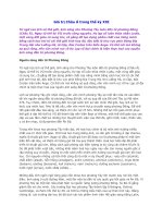
known as the visible portion of the spectrum. Figure 1.1 shows the
electromagnetic spectrum, with the visible portion expanded.
As you can see, the visible part of the spectrum covers the
wavelengths from ultraviolet, which is commonly associated with
skin damage from the sun, to the infrared, which is associated with
the heat felt from the sun. This points out the fact that the shorter
the wavelength, the higher the energy in electromagnetic radiation.
The ‘visible’ section of the electromagnetic spectrum (see Figure
1.1), when seen simultaneously, appears as white light, such as
bright sunlight at noon on a clear day. When white light strikes an
object, part of it is reflected, and part is absorbed. For example, a
ball which is seen as blue is, in fact, reflecting the blue wavelengths
and absorbing all the others.
Our eyes are sensitive to all the wavelengths within the visible
spectrum. However, as stated before, they act as ‘antennas’ to
receive reflected light and, like antennas, they are tuned to a specific
frequency. In the case of the eye, that frequency lies approximately
at the center of the visible spectrum, and has a wavelength of 550
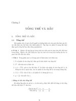
nanometers. This means that the sensitivity of the average eye peaks
in the yellow–green portion of the spectrum, and falls off sharply
as the limits of the spectrum are approached. Figure 1.2 shows this
as a bell curve of eye response relative to light wavelength.
Our eyes not only have to respond to a wide range of
wavelengths, but they also must automatically adjust to a
constantly varying light intensity. To see how this is accomplished,
2 The Lit Interior
Figure 1.1. The electromagnetic spectrum (source: Philips Lighting Handbook).
WAVELENGTH IN NANOMETRES
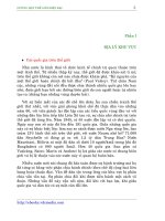
let’s take a look at the components of the eye, as shown in Figure
1.3. The ‘front end’ of the eye acts much like a camera to regulate
the incoming light and focus it on the retina. This ‘front end’ is
made up of the cornea, the clear outer layer of the eye, and the
pupil, an opening whose size is constantly being adjusted by the iris
to compensate for varying light intensity, and the lens, which uses
the ciliary muscle to change its shape to focus the light on a special
part of the retina, called the fovea. The retina contains from 75 to
150 million rods and about 7 million cones, which make up the
actual antennae tuned to the visible spectrum. The rods and cones
convert light energy into neural signals that are transmitted to the
brain through the optic nerve.
Rods cannot detect lines, points, or colors. They can only detect
light and dark tones in an image. Rods are highly sensitive, and
they can distinguish outlines of objects in almost complete darkness.
Cones are even more sensitive – they detect the lines and points of
an image, such as the words you are now reading. Cones also detect
The design medium 3
Figure 1.2. Color response of the eye (source: Philips Lighting Handbook).
Figure 1.3. Components of the eye (source: F.H. Jones).
color, and there are three types of cones present in the eye: one that
is sensitive to the blue–violet end of the spectrum; one sensitive to
the yellow–green, or middle of the spectrum; and one sensitive to
the red end of the spectrum.
The fovea contains only cones, and provides the optimal recep-
tion in brighter light conditions. Muscles controlling the eye work
in conjunction with the ciliary muscles controlling the lens to keep
the viewed object focused on the fovea. That’s why you are moving
your eyes while reading this page.
In higher light levels, the cones are the main receptors of light,
and the response of the eye to the varying wavelengths of light is
as shown in Figure 1.2. In a very low level of light, the cones cease
to function, and the sensitivity peak of the eye shifts toward the
light with the higher energy wavelengths at the blue end of the
spectrum. This is known as the blue shift, or Purkinje effect, and
it is the reason that, under very dim ambient light, the eye will
perceive blue light as inordinately bright. This is why police cars in
the US have switched from red to blue emergency lights.
As we get older, the components of the eye begin to deteriorate.
The ciliary muscles get weaker, the lens loses elasticity, and our
ability to focus, particularly on close objects, becomes less. The lens
itself yellows with age, which affects color vision, particularly the
differentiation between blues and greens. The lens also becomes
thicker and less transparent, which results in light scattering and
‘night blindness’, or extreme sensitivity to glare. The pupil gets
smaller, which reduces the overall amount of light which reaches
the retina. The result of all this deterioration is that older people
need more illumination, larger print, and more contrast in order to
see clearly – and to function comfortably.
Now that we know something about the eye, let’s take a look at
some of the mechanics of those light rays which are constantly
bombarding our rods and cones.
Light mechanics
Light travels in a straight line until it strikes a surface. It is then
modified by either transmission, refraction, reflection, or absorp-
tion. Figure 1.4 illustrates each of these light modifiers.
Light can also be modified by polarization, diffraction, or interfer-
ence by other light rays, but these play a very small part in light-
ing design. For now, let’s concentrate on the ‘big four’, and see how
they affect light rays.
4 The Lit Interior
1. Transmission
There are three general categories of transmission: Direct trans-
mission occurs when light strikes transparent material which can
be seen through. These materials absorb almost none of the light
in its passage through the material, and do not alter the direction
of the light ray. Spread transmission occurs with translucent materi-
als in which the light passing through the material emerges in a
wider angle than the incident beam, but the general direction of the
beam remains the same. Diffuse transmission occurs with semi-
opaque materials such as opal glass, and the light passing through
the material is scattered in all directions. These materials absorb
some of the light, and the emerging rays are of less intensity than
the transmitted rays. Figure 1.5 illustrates the types of transmission.
The design medium 5
Figure 1.4. Types of light modification (source: F.H. Jones).
Figure 1.5. Types of light transmission (source: F.H. Jones).
2. Refraction
Refraction occurs when a beam of light is ‘bent’ as it passes from
air to a medium of higher density, or vice versa. This occurs because
the speed of the light is slightly lower in the medium of higher
density. Two commonly used refractive devices are prisms and
lenses. A prism is made of transparent material which has non-
parallel sides. A large prism slows down the various wavelengths
of light by different amounts and can be used to divide the light
ray into its color components; smaller prisms are used in lighting
fixtures to lower brightness or to redirect light into useful zones.
Lenses are used to cause parallel light rays to converge or diverge,
focusing or spreading the light, as desired. Figure 1.6 illustrates
some refractive devices.
3. Reflection
Reflection occurs when light strikes a shiny opaque surface, or any
shiny surface at an angle. Reflection can be classified in three
general categories: specular reflection, spread reflection and diffuse
reflection. Specular reflection occurs when light strikes a highly
polished or mirror surface. The ray of light is reflected, or bounced
off the surface at an angle equal to that at which it arrives. Very
little of the light is absorbed, and almost all of the incident light
leaves the surface at the reflected angle. Spread reflection occurs
when a ray of light strikes a polished but granular surface. The
reflected rays are spread in diverging angles, due to reflection from
the facets of the granular surface. Diffuse reflection occurs when
6 The Lit Interior
Figure 1.6. Refractive devices (source: F.H. Jones).
the ray of light strikes a reflective opaque but non-polished surface,
such as flat white paint. Figure 1.7 shows the types of reflection.
4. Absorption
Absorption occurs when the object struck by the light ray retains
the energy of the ray in the form of heat. If you remember the blue
ball example, the ball reflects only the blue wavelengths of the
incident light, and absorbs all of the others. If the ball were in the
sunlight, this energy absorption would heat the ball up. Some
surfaces, like flat black paint, absorb nearly all of the incident light
rays. These surfaces, such as those of a solar collector panel, tend
to get very hot when placed in the sunlight.
With these principles in mind, you can predict how the light itself
will behave when used with the various control devices. Now let’s
look at some of the factors of light which affect the way we see.
The design medium 7
Figure 1.7. Specular, spread, and diffuse reflection (source: F.H. Jones).
Physical factors
In addition to color, the four factors which determine the visibility
of an object are: size, contrast, luminance, and time. Of the four,
luminance, or brightness, or the strength of the light falling on the
rods and cones, is the underlying dominant factor. Let’s look at
these factors in more detail.
1. Size
Size is considered because the larger or nearer an object, the easier
it is to see. A larger object, of course, reflects more total light, and
offers a stronger stimulation of the rods and cones. Also, as we will
see in a moment, light adheres to the inverse square law. This means
that the strength of the reflected light decreases as the square of the
distance between the object and the eye. In other words, the closer
the object, the stronger the reflected light.
2. Contrast
Contrast is simply the difference in brightness of an object and its
background. Distinct contrast allows the brain to differentiate easily
between areas of strong and mild visual stimulation. For example,
black words on white paper are read easily, but gray lettering on a
slightly lighter gray paper is much harder to interpret.
3. Luminance
Luminance, simply put, is the brightness of an object, or the strength
of the light reflected from it. The greater the luminance, the stronger
the visual stimulation, and the easier the object is to see.
4. Time
Time refers to how long it takes to see an object clearly. Under the
best conditions, it takes slightly less than one-sixteenth of a second
for the eye to register an image. In a dim setting, it takes longer.
This is especially important where motion is involved, such as in
night driving.
Obviously, the luminance of an object, or the quantity of light
reflected from it, determines the level of visual stimulation the
object provides. Now it is time to look more closely at the mechan-
ics of light quantity, and also to investigate another factor that
influences visual acuity, namely, light quality.
8 The Lit Interior
Light quantity
In evaluating light quantity, it will be helpful to examine the afore-
mentioned inverse square law, and some of the nomenclature that
is used to describe the features of light. Succinctly put, the inverse
square law as applied to lighting states that: ‘the luminance of an
object is directly proportional to the light output of the illuminat-
ing source, and inversely proportional to the square of the distance
between the source and the object’. At the risk of losing a few of
you to the geometry, let’s look at Figure 1.8, which graphically illus-
trates the inverse square law.
Light output from a source is normally expressed in candlepower,
and light output in a given direction is expressed in candelas. The
density of light flux radiating from the source is expressed in
lumens, and the luminance, or light reflected from an object is
expressed in footcandles. Footcandles has units of lumens per
square foot. Figure 1.8 shows a point source of uniform candle-
power, having 100 candela in all directions. If we approximate
light propagation in a solid angle of 1 steradian and go out a
distance of 1 foot from the source, we see that the angle circum-
scribes an area of 1 square foot. The glossary defines a lumen as
the flux density generated within 1 steradian by a point source of
1 candela. We have 100 candela in the source of Figure 1.8, so the
flux density will be 100 lumens. Using the lumens per square foot
definition, we see that the luminance at 1 foot will be 100/1, or
100 footcandles (100 fc). If we go out 2 feet from the source, we
see that the area circumscribed by the steradian envelope is now
2 squared, or 4 square feet. Similarly, at 3 feet, the area is 9 square
The design medium 9
Figure 1.8. Inverse square law (source: F.H. Jones).
feet. Corresponding luminances are 100/4, or 25 fc, and 100/9, or
11 fc, respectively. For the mathematicians among you, this
relationship can be expressed mathematically as I = L/D
2
, where I
is illumination in footcandles, L is the luminance of the source in
lumens, and D
2
is the square of the distance in feet from the source
to the point under examination.
The inverse square law works pretty well in predicting the illumi-
nation on a surface from a point source directly above the surface,
but what happens when we want to predict the effects of a source
that is at an angle to the surface under consideration? We can use
an old static mechanics trick and expand the inverse square law to
take care of the angle by breaking the angle down into its two
components, one parallel to and one normal to the surface, and
then discarding the parallel component. Figure 1.9a illustrates this
graphically.
Now, if you’ve ever had a statics course, you’ll remember that a
force applied to a Point P on a beam at an angle from the normal
is treated this way, and that the downward component of the force
is equal to the total force times the cosine of . If you’ve never had
statics, no matter, it still works that way. Taking luminance L as
the ‘force’ of the light, and using the inverse square law, we can
say that the illumination I on a point from a source that is at an
angle X from being directly above the point, and at a distance D
from the point is: I = L cos X/D
2
. This is called the cosine law of
incidence. To get some idea of what this means, look at the light
sources above you and all around you. All of these contribute to
10 The Lit Interior
Figure 1.9. Two-component force vector.
(a) (b)
the total illumination falling on your desktop. If you have a good
calculator, and about a month of free time, you can calculate
exactly what that illumination is, using this equation.
Fortunately, we don’t have to get bogged down in extensive,
tedious calculations of this sort. As we will see in a later chapter,
there are plenty of good computer programs out there to perform
these calculations for you. It is, however, helpful to know the logic
behind the calculations, so that you will be able differentiate
between valid output and computer-generated gibberish.
So there you have the factors involved in the quantity of light
that illuminates a chosen area. To review in a nutshell, these are
the strength in candlepower of the illuminating sources; the distance
those sources are from the area; and the angle those sources are
from the normal to the surface of the area. Adequate quantity of
light, however, doesn’t always insure good visibility. The quality of
the light is often as important as the quantity.
Light quality
What do we mean by light quality, and what are the factors which
contribute to ‘good’ or ‘bad’ quality illumination? Simply put, good
quality illumination is that which provides a high level of visual
comfort, and allows us to view tasks clearly and easily. This affects
our psyche in a positive way. On the other hand, poor visual comfort
illumination irritates us. The four most important factors affecting
visual comfort are glare, brightness ratio, diffusion, and color rendi-
tion. Let’s look now at each of these factors in greater detail.
Glare
We’ve all experienced glare in our everyday lives: bright lighting
fixtures located in your field of view, or sunlight coming through
a window. This is known as discomfort glare, and the degree of
discomfort inflicted depends on the number, size, position, and
luminance of the glare sources. In interior lighting design, we are
primarily concerned with discomfort glare from windows and
overhead lighting fixtures. Other forms of glare are disability glare
and veiling reflections. Disability glare obliterates task contrast, and
scatters the light within your eye to the point that visibility is
reduced to zero. A common example is glare from a glossy
magazine page that makes it impossible to read the page. Veiling
reflections, such as lighting fixture ‘images’ on your computer
monitor, make it hard to see what is on the screen. The severity of
The design medium 11
glare in any form is primarily dependent on two factors: the bright-
ness and position of the source.
Brightness ratio
The brightness ratio is the brightness contrast between the task and
the background. This affects the amount of work our eyes have to
do in order for us to perform the task. For example, a high bright-
ness task in a low brightness surrounding forces the eye to contin-
ually adjust from one light level to the other. Conversely, a low
brightness task surrounded by a bright background tends to obscure
contrast, and the eye tends to be attracted away from the task.
Obviously, a balance between task and background brightness is
desirable for effective viewing.
Diffusion
Contrary to the above factors, which affect viewing negatively,
diffusion generally improves visual comfort. Diffusion results from
light arriving at the task from many different directions. A highly
diffuse lighting system will produce no penumbra, or sharply
defined shadows. Diffuse lighting is desirable in office areas where
computers are in use, in school classrooms, and in library reading
areas. Diffuse lighting is accomplished through the use of many low
brightness fixtures, or through the use of indirect lighting, where
the light is reflected from diffuse surfaces, such as a white ceiling,
before reaching the task.
Color rendition
Color of light affects the ‘mood’, or emotional aspects of a space.
It also affects the accuracy with which we perform tasks. We’ve all,
at one time or another, purchased a garment under artificial light-
ing, only to have it change color when we got it out into the
sunlight. That happens because the artificial light source does not
contain the full visible spectrum of colors, as does the sunlight. As
noted before with the blue ball example, we see only those colors
which are reflected from a surface. Obviously, those tasks that
involve color discrimination should be lighted by a source that
contains as much of the visible spectrum as possible. In other situa-
tions, the mood of the environment can be altered by the use of
‘warm’ or ‘cool’ colors, high in reds, or blues, respectively.
Unlike light quantity, light quality is subjective in nature, and is
not easy to calculate by mathematical formulae. The lighting indus-
12 The Lit Interior
try has, however, come up with several methods that the designer
can use to evaluate the relative quality of lighting systems. The first
of these is equivalent sphere illumination (ESI). This is a complicated
method of relating illumination of a task on a surface within the
design space to that of a task on a surface in the center of a sphere
that is equally illuminated throughout. The logic being that the
lighted sphere will provide the optimum illumination, and that the
space should be designed to match the footcandle requirement of the
sphere as closely as possible. For example, if a task requiring 100 fc
in the design space was put into the sphere, and the lighting level
was adjusted to provide the same task visibility, and that level was
60 fc, then the ESI would be 60 fc. Equivalent sphere illumination
takes into account room geometry and reflectance, fixture charac-
teristics, and viewer position. Needless to say, only fixture manufac-
turers with big computers attempt ESI calculations. Another
comparison type system evaluator is the relative visual performance
(RVP) factor, which is expressed in percentages. The RVP represents
the percentage likelihood that a standardized visual task can be
performed within the designed lighting system. Age of the viewer,
luminance and contrast are all included in RVP calculations. When
comparing systems, the one with the higher RVP will provide better
light quality. Also expressed in percentages is the visual comfort
probability (VCP), which is the percent of viewers positioned in a
specific location, viewing in a specific direction, who would find the
lighting system acceptable in terms of discomfort glare. Visual
comfort probability takes into account room geometry and
reflectances, fixture number, type and luminance. As with RVP, the
higher the VCP, the better the light quality of the installation.
The lighting industry has done a yeoman’s job of trying to
quantify the factors of light quality so that the above evaluators
may be calculated numerically. There are so many non-direct factors
involved, however, that these calculations are best left to fixture
manufacturers with plenty of time and people, and large comput-
ers. Most fixture manufacturers publish some sort of visual comfort
data for their fixtures. A good lighting designer is aware of the
causes of visual discomfort, and develops an innate ‘feel’ for which
fixtures will perform well where, rather than trying to rely solely
on numbers and calculations to provide good light quality.
The psychology of lighting
A seasoned lighting designer can visualize how a given lighting
system will look and perform within a space. He also can predict
The design medium 13
how an observer will react to the system. This insight is gained with
experience, of course, but certain basic relationships of light and
space and the psyche are always present, and are worth mention-
ing. The first is the location of the plane of brightness, or the bright-
est surface in the space. Figure 1.10 illustrates some different planes
of brightness.
A ceiling left in shadow creates a secure, intimate, and relaxing
‘cave’ environment suitable for lounges and casual dining. High
brightness on the ceiling creates the bright, efficient, working
atmosphere desirable for offices, classrooms, and kitchens. Bright-
ness on the vertical planes draws attention to the walls and expands
the space visually, and is appropriate for art galleries, merchandis-
ing, and lobbies. Such facilities often also use variations of light
intensity on the walls to accentuate a desired feature.
Variations of light intensity form areas of light and shadow,
which are desirable if you are trying to create a ‘mood’ environ-
ment, rather than an evenly illuminated workplace. The interplay
of light and shadow add variety to a space, and provide visual relief
to an otherwise monotonous environment. Scallops on a wall from
downlights, shadows on the ceiling from uplights, or highlights
from accent lighting create areas of visual interest, and can draw
attention to a desired area or object. The designer must be careful
not to overdo it, though, because too many lighting effects in one
space have roughly the same visual effect that too many sidebars,
colors, and font styles do to a magazine page: the original design
intent is obscured or obliterated.
It is always best to work with the architect from the outset of a
project to get in tune with the flavor or mood that he or she is
trying to create in a space. Architectural features can be modeled
through the use of shadows, as can objects within the space. A
three-dimensional object lighted directly from in front will appear
14 The Lit Interior
Figure 1.10. Planes of brightness (source: F.H. Jones).