Astm d 5533 98e1
Bạn đang xem bản rút gọn của tài liệu. Xem và tải ngay bản đầy đủ của tài liệu tại đây (2.38 MB, 101 trang )
NOTICE: This standard has either been superceded and replaced by a new version or discontinued.
Contact ASTM International (www.astm.org) for the latest information.
Designation: D 5533 – 98e1
An American National Standard
Standard Test Method for
Evaluation of Automotive Engine Oils in the Sequence IIIE,
Spark-Ignition Engine1
This standard is issued under the fixed designation D 5533; the number immediately following the designation indicates the year of
original adoption or, in the case of revision, the year of last revision. A number in parentheses indicates the year of last reapproval. A
superscript epsilon (e) indicates an editorial change since the last revision or reapproval.
e1 NOTE—Figure 15 was deleted and Figs. 14 and 17 were corrected editorially in March 1999.
INTRODUCTION
The test method described in this standard can be used by any properly equipped laboratory, without
the assistance of anyone not associated with that laboratory. However, the ASTM Test Monitoring
Center (TMC) 2 provides reference oils and an assessment of the test results obtained on those oils by
the laboratory (see Annex A1). By this means, the laboratory will know whether their use of the test
method gives results statistically similar to those obtained by other laboratories. Furthermore, various
agencies require that a laboratory utilize the TMC services in seeking qualification of oils against
specifications. For example, the U.S. Army imposes such a requirement, in connection with several
Army engine lubricating oil specifications.
Accordingly, this test method is written for use by laboratories which utilize the TMC services.
Laboratories which choose not to use those services may simply ignore those portions of the test
method which refer to the TMC.
This test method may be modified by means of Information Letters issued by the TMC. In addition,
the TMC may issue supplementary memoranda related to the test method (see Annex A1). Users of
this test method shall contact the ASTM Test Monitoring Center to obtain the most recent of these.
in each system may not be exact equivalents; therefore, each
system must be used independently of the other, without
combining values in any way.
1.3 This standard does not purport to address all of the
safety concerns, if any, associated with its use. It is the
responsibility of the user of this standard to establish appropriate safety and health practices and determine the applicability of regulatory limitations prior to use.
1.4 This test method is arranged as follows:
1. Scope
1.1 This test method covers an engine test procedure for
evaluating automotive engine oils for certain high-temperature
performance characteristics, including oil thickening, sludge
and varnish deposition, and oil consumption, as well as engine
wear. Such oils include both single viscosity grade and
multiviscosity grade oils which are used in both spark-ignition,
gasoline-fueled engines, as well as in diesel engines. 2
NOTE 1—Companion test methods used to evaluate engine oil performance for specification requirements are discussed in SAE J304.
Subject
Introduction
Scope
Referenced Documents
Terminology
Summary of Test Method
Significance and Use
Apparatus
Laboratory
Drawings
Specified Equipment
Test Engine
Engine Parts
Hold-Back Fixture
Engine Speed and Load Control
Engine Cooling System
Flushing Tank
Coolant Mixing Tank
Jacketed Rocker Cover, Intake Manifold Crossover, and
Breather Tube Cooling Systems
External Oil-Cooling System
Fuel System
1.2 The values stated in either acceptable SI units or in other
units shall be regarded separately as standard. The values stated
1
This test method is under the jurisdiction of ASTM Committee D-2 on
Petroleum Products and Lubricants and is the direct responsibility of Subcommittee
D02.B0.01 on Passenger Car Engine Oils.
The multi-cylinder engine test sequences were originally developed in 1956 by
an ASTM Committee D-2 group. Subsequently, the procedures were published in an
ASTM special technical publication. The Sequence IIIE method was published as
Research Report RR:D02-1225, dated April 1, 1988.
Current edition approved Dec. 10, 1998. Published February 1999. Originally
published as D 5533 – 97a. Last previous edition D 5533 – 96.
2
ASTM Test Monitoring Center, 6555 Penn Ave., Pittsburgh, PA 15206-4489.
For other information, refer to Research Report RR:D02-1225 Multicylinder Test
Sequences for Evaluating Automotive Engine Oils—Part 2 Sequence IIIE. This
research report and this test method are supplemented by Information Letters and
memoranda issued by the ASTM Test Monitoring Center. This edition incorporates
revisions in all information letters through No. 98–1.
Copyright © ASTM, 100 Barr Harbor Drive, West Conshohocken, PA 19428-2959, United States.
1
Section
1
2
3
4
5
6
6.1
6.2
6.3
6.4
6.4.1
6.4.2
6.5
6.6
6.7
6.8
6.9
6.10
6.11
NOTICE: This standard has either been superceded and replaced by a new version or discontinued.
Contact ASTM International (www.astm.org) for the latest information.
D 5533
Subject
Carburetor Air Supply Humidity, Temperature, and Pressure
Temperature Measurement
Thermocouple Location
Air-to-Fuel Ratio Determination
Exhaust and Exhaust Back Pressure Systems
Blowby Flow Rate Measurement
Pressure Measurement and Pressure Sensor Location
Reagents and Materials
Test Fuel
Additive Concentrate for the Coolant
Coolant Preparation
Pre-Test Cleaning Materials
Post-Test Cleaning Materials
Sealing and Anti-seize Compounds
Hazards
Test Oil Sample Requirements
Preparation of Apparatus
Oil Heat Exchanger Cleaning
Jacketed Rocker Cover Cleaning
Breather Tube Cleaning
Cleaning of Special Stainless Steel Parts
Intake Manifold Cleaning
Precision Rocker Shaft Follower Cleaning
Cleaning of Engine Parts (other than the block and heads)
Engine Block Cleaning
Cylinder Head Cleaning
Engine Build-up Procedure
General Information
Special Parts
Hardware Information
Sealing Compound Applications
Fastener Torque Specifications and Torquing Procedures
Main Bearing Cap Bolts
Cylinder Head Bolts
Intake Manifold Bolts
Torques for Miscellaneous Bolts, Studs, and Nuts
Parts Replacement
Engine Block Preparation
Piston Fitting and Numbering
Piston Ring Fitting
Pre-Test Camshaft and Lifter Measurements
Camshaft Bearing Installation
Camshaft Preparation
Camshaft Installation
Installation of Camshaft Hold-Back Fixture
Camshaft Sprocket, Crankshaft Sprocket, and Chain
Camshaft Thrust Button
Main Bearings
Crankshaft
Main Bearing Cap Installation
Crankshaft End Play
Piston Pin Installation
Piston Installation
Harmonic Balancer
Connecting Rod Bearings
Engine Front Cover
Coolant Inlet Adapter
Timing Mark Accuracy
Oil Pump
Oil Dipstick Hole
Oil Pan
Cylinder Head Assembly
Adjustment of Valve Spring Loads
Cylinder Head Installation
Hydraulic Valve Lifters
Pushrods
Precision Rocker Shaft Assembly
Valve Train Loading
Intake Manifold
Rocker Cover Deflectors and Stanchions
Rocker Covers
Water Inlet Adapter
Breather Tube
Coolant Outlet Adapter
Oil Fill Adapter
Oil Filter Adapter
Oil Sample Valve
Subject
Section
Ignition System
10.10.47
Carburetor
10.10.48
Accessory Drive Units
10.10.49
Exhaust Manifolds, Water-Cooled
10.10.50
Engine Flywheel
10.10.51
Pressure Checking of Engine Coolant System
10.10.52
Lifting of Assembled Engines
10.11
Mounting the Engine on the Test Stand
10.12
External Cooling System Cleaning
10.13
Engine Coolant Jacket and Intake Manifold Coolant Crossover Cleaning (Flushing)
10.14
Coolant Charging
10.15
Test Oil Charging
10.16
Engine Oil Pump Priming and Cam-and-Lifter Pre-Test Lubrication
10.17
Calibration
11
Laboratory and Engine Test Stand Calibration
11.1
Testing of Reference Oils
11.1.1
Reference Oil Test Frequency
11.1.2
Reporting of Reference Oil Test Results
11.1.3
Evaluation of Reference Oil Test Results
11.1.4
Status of Non-reference Oil Tests Relative to Reference Oil
Tests
11.1.5
Status of Test Stands Used for Non-Standard Tests
11.1.6
Instrumentation Calibration
11.2
Engine Operating Procedure
12
Dipstick and Hole Plug
12.1
Oil Fill Adapter
12.2
Carburetor Air Inlet Supply Line
12.3
Engine Start-up and Shutdown Procedures
12.4
Start-up
12.4.1
Shutdown
12.4.2
Non-Scheduled Shutdowns
12.4.3
Oil Sampling
12.5
Oil Leveling
12.6
Checks for Glycol Contamination
12.7
Air-to-Fuel-Ratio Measurement and Control
12.8
Blowby Flow Rate Measurement
12.9
NOx Determinations
12.10
Data Recording
12.11
Ignition Timing Run (Ten Minutes)
12.12
Break-In (4 Hours)
12.13
Engine Oil Quality Testing (64 Hours)
12.14
Test Termination
12.15
Determination of Test Results
13
Engine Disassembly
13.2
Preparation of Parts for Rating of Sticking, Deposits, and
Plugging
13.3
Rating Environment
13.4
Part Sticking
13.5
Sludge Rating
13.6
Piston Skirt Deposits Rating
13.7
Oil Ring Land Deposits Rating
13.8
Part Plugging Observations
13.9
Visual Inspection for Scuffing and Wear
13.10
Post-Test Camshaft and Lifter Wear Measurements
13.11
Connecting Rod Bearing Weight Loss
13.12
Viscosity Test
13.13
Blowby Flow Rate Measurements
13.14
Oil Consumption Computation
13.15
Photographs of Test Parts
13.16
Retention of Representative Test Parts
13.17
Severity Adjustments
13.18
Determination of Operational Validity
13.19
Report
14
Report Forms
14.1
Use of SI Units
14.2
Precision of Reported Units
14.3
Deviations from Test Operational Limits
14.4
Oil Pressure Plot
14.5
Precision and Bias
15
Keywords
16
Section
6.12
6.13
6.13.1
6.14
6.15
6.16
6.17
7
7.1
7.2
7.3
7.4
7.5
7.6
8
9
10
10.1
10.2
10.3
10.4
10.5
10.6
10.7
10.8
10.9
10.10
10.10.1
10.10.2
10.10.3
10.10.4
10.10.5
10.10.5.1
10.10.5.2
10.10.5.3
10.10.5.4
10.10.6
10.10.7
10.10.8
10.10.9
10.10.10
10.10.11
10.10.12
10.10.13
10.10.14
10.10.15
10.10.16
10.10.17
10.10.18
10.10.19
10.10.20
10.10.21
10.10.22
10.10.23
10.10.24
10.10.25
10.10.26
10.10.27
10.10.28
10.10.29
10.10.30
10.10.31
10.10.32
10.10.33
10.10.34
10.10.35
10.10.36
10.10.37
10.10.38
10.10.39
10.10.40
10.10.41
10.10.42
10.10.43
10.10.44
10.10.45
10.10.46
Annexes
The Role of the ASTM Test Monitoring Center (TMC) and the
Calibration Program
Sequence IIIE Engine Test Parts
2
A1
A2
NOTICE: This standard has either been superceded and replaced by a new version or discontinued.
Contact ASTM International (www.astm.org) for the latest information.
D 5533
Subject
Sequence IIIE Test Parts and Drawings
Sequence IIIE Test Fuel Analysis
Sequence IIIE Test Control Chart Technique for Developing and
Applying Severity Adjustments
Sequence IIIE Test Reporting
Sequence IIIE Test Air-to-Fuel Ratio
Sequence IIIE Test Blowby Flow Rate Correction Factor
Appendixes
Sequence IIIE Test—Engine Build Measurement Worksheets
Sequence IIIE Test—Pre- and Post-Test Measurements
Sequence IIIE Test—Cam Lobe Oiling Wand
Sequence IIIE Test—Operational Logs, Checklists, and Worksheets
Sequence IIIE Test—Rating Worksheets
Oils for Inhibition of Deposit Formation and Wear in a
Spark-Ignition Internal Combustion Engine Fueled with
Gasoline and Operated Under Low-Temperature, LightDuty Conditions8
E 29 Practice for Using Significant Digits in Test Data to
Determine Conformance with Specifications9
E 270 Definitions of Terms Relating Liquid Penetrant Examination10
E 344 Terminology Relating to Thermometry and Hydrometry11
E 380 Practice for Use of the International System of Units
(SI)9 (The Modernized Metric System)
E 1119 Specification for Industrial Grade Ethylene Glycol12
G 40 Terminology Relating to Wear and Erosion13
2.2 Military Specification:14
MIL-L-2104, Lubricating Oil, Internal Combustion Engine,
Tactical Service
2.3 SAE Standards:15
J183, Engine Oil Performance and Engine Service Classification (Other Than “Energy-Conserving”)
J304, Engine Oil Tests
Section
A3
A4
A5
A6
A7
A8
X1
X2
X3
X4
X5
2. Referenced Documents
2.1 ASTM Standards:
D 16 Definitions of Terms Relating to Paint, Varnish, Lacquer, and Related Products3
D 86 Test Method for Distillation of Petroleum Products4
D 130 Test Method for Detection of Copper Corrosion from
Petroleum Products by the Copper Strip Tarnish Test4
D 156 Test Method for Saybolt Color of Petroleum Products (Saybolt Chromometer Method)4
D 235 Specification for Mineral Spirits (Petroleum Spirits)
(Hydrocarbon Dry Cleaning Solvent)5
D 287 Test Method for API Gravity of Crude Petroleum and
Petroleum Products (Hydrometer Method)4
D 323 Test Method for Vapor Pressure of Petroleum Products (Reid Method)4
D 381 Test Method for Existent Gum in Fuels by Jet
Evaporation4
D 445 Test Method for Kinematic Viscosity of Transparent
and Opaque Liquids (and the Calculation of Dynamic
Viscosity)4
D 525 Test Method for Oxidation Stability of Gasoline
(Induction Period Method)4
D 1266 Test Method for Sulfur in Petroleum Products
(Lamp Method)4
D 2422 Classification of Industrial Fluid Lubricants by
Viscosity System4
D 2699 Test Method for Knock Characteristics of Motor
Fuels by the Research Method6
D 2700 Test Method for Knock Characteristics of Motor
and Aviation Fuels by the Motor Method6
D 2982 Test Methods for Detecting Glycol-Base Antifreeze
in Used Lubricating Oils7
D 3237 Test Method for Lead in Gasoline by Atomic
Absorption Spectrometry7
D 4175 Terminology Relating to Petroleum, Petroleum
Products, and Lubricants7
D 4485 Specification for Performance of Engine Oils7
D 5119 Test Method for Evaluation of Automotive Engine
Oils in the CRC L-38 Spark-Ignition Engine8
D 5302 Test Method for Evaluation of Automotive Engine
3
Annual
Annual
5
Annual
6
Annual
7
Annual
8
Annual
4
Book
Book
Book
Book
Book
Book
of
of
of
of
of
of
ASTM
ASTM
ASTM
ASTM
ASTM
ASTM
Standards,
Standards,
Standards,
Standards,
Standards,
Standards,
Vol
Vol
Vol
Vol
Vol
Vol
3. Terminology
3.1 Definitions:
3.1.1 blowby, n—in internal combustion engines, the combustion products and unburned air-and-fuel mixture that enter
the crankcase.
3.1.2 BTDC, adj—abbreviation for Before Top Dead Center; used with the degree symbol to indicate the angular
position of the crankshaft relative to its position at the point of
uppermost travel of the piston in the cylinder.
3.1.3 calibrate, v—to determine the indication or output of
a measuring device with respect to that of a standard. E 344
3.1.4 clogging, n—the restriction of a flow path due to the
accumulation of material along the flow path boundaries.
3.1.5 corrosion, n—the chemical or electrochemical oxidation of the surface of metal which can result in loss of material
or accumulation of deposits.
E 270
3.1.6 debris, n—in internal combustion engines, solid contaminant materials unintentionally introduced into the engine
or resulting from wear.
3.1.7 engine oil, n—a liquid that reduces friction or wear, or
both, between the moving parts within an engine, and also
serves as a coolant.
D 4485
3.1.8 free piston ring, n— in internal combustion engines, a
piston ring which will fall in its groove under the force of its
own weight when the piston is moved from a vertical (axis
orientation) to a horizontal position.
9
Annual Book of ASTM Standards, Vol 14.02.
Discontinued, see 1991 Annual Book of ASTM Standards, Vol 03.03.
11
Annual Book of ASTM Standards, Vol 14.03.
12
Annual Book of ASTM Standards, Vol 15.05.
13
Annual Book of ASTM Standards, Vol 03.02.
14
Available from Standardization Documents Order Desk, Bldg. 4 Section D,
700 Robbins Ave., Philadelphia, PA 19111-5094, Attn: NPODS.
15
Available from Society of Automotive Engineers, Inc., 400 Commonwealth
Drive, Warrendale, PA 15096-0001. These standards are not available separately.
Order either the SAE Handbook Vol 3, or the SAE Fuels and Lubricants Standards
Manual HS-23.
10
06.01.
05.01.
06.04.
05.04.
05.02.
05.03.
3
NOTICE: This standard has either been superceded and replaced by a new version or discontinued.
Contact ASTM International (www.astm.org) for the latest information.
D 5533
mechanical or chemical action, or of a combination of mechanical and chemical actions.
D 5302
3.2 Definitions of Terms Specific to This Standard:
3.2.1 build-up oil, n—noncompounded ISO VG 32 (SAE
20) oil18,19 used in lubricating the Sequence IIIE parts during
engine assembly, and in coating parts following rating.
3.2.2 calibrated test stand, n—a test stand (see 3.2.29) on
which Sequence IIIE engine oil tests are conducted within the
lubricant test monitoring system as administered by the ASTM
TMC (see 11.1).
3.2.3 Central Parts Distributor (CPD)—18 ,20n—the manufacturer and supplier of many of the parts and fixtures used in
this test method.
3.2.3.1 Discussion—Because of the need for rigorous inspection and control of many of the parts used in this test
method, and because of the need for careful manufacture of
special parts and fixtures used, a company having the capabilities to provide the needed services has been selected as the
official supplier for the Sequence IIIE test method. This
company, Bowden Manufacturing Corp.,18,20 works closely
with the original parts suppliers, with the Test Developer,21 and
with the ASTM groups associated with the test method to help
ensure that the equipment and materials used in the method
function satisfactorily.
3.2.4 controlled primary parameter, n—a test parameter
over which the testing laboratory has direct control, that has the
potential for significant impact on test severity should there be
a large difference between the test average and the target
specification.
3.2.5 controlled secondary parameter, n— a test parameter
over which the testing laboratory has direct control, that has
less potential for significant impact on test severity than a
controlled primary parameter, should there be a large difference between the test average and the target specification.
3.2.6 correction factor, n—a mathematical adjustment to a
test result to compensate for industry-wide shifts in severity.
3.2.7 CPD Special Test Parts (STP), n—parts that do not
meet all the definitions of critical parts, non-production parts,
or SPO parts, but must be obtained from the Central Parts
Distributor.
3.2.8 critical parts (CP), n—those components used in the
test, which are known to affect test severity.
3.2.8.1 Discussion—They must be obtained from the Central Parts Distributor, who will identify them with either a serial
number or a batch lot control number.
3.2.9 EWMA, n—exponentially-weighted moving average.
3.2.10 lead salts, n—salt formations which develop on the
central contact area of a piston skirt after the piston has been
removed from the engine following a Sequence IIIE test.
3.1.8.1 Discussion—In determining this condition, the ring
may be touched slightly to overcome static friction.
3.1.9 lubricant, n—any material interposed between two
surfaces that reduces the friction or wear, or both, between
them.
3.1.10 noncompounded engine oil, n—a lubricating oil having a viscosity within the range of viscosities of oils normally
used in engines, and that may contain anti-foam agents or pour
depressants, or both, but not other additives.
D 5119
3.1.11 non-reference oil, n—any oil other than a reference
oil; such as a research formulation, commercial oil, or candidate oil.
Subcommittee B Glossary16
3.1.12 oxidation, n—of engine oil, the deterioration of the
oil which is observed as increased viscosity, sludge formation,
varnish formation, or a combination thereof, as a result of
chemical and mechanical action.
D 5119
3.1.13 reference oil, n—an oil of known performance characteristics, used as a basis for comparison.
3.1.13.1 Discussion—Reference oils are used to calibrate
testing facilities, to compare the performance of other oils, or
to evaluate other materials (such as seals) that interact with
oils.
Subcommittee B Glossary
3.1.14 rust (coatings), n—the reddish material, primarily
hydrated iron oxide, formed on iron or its alloys resulting from
exposure to humid atmosphere or chemical attack.
D 16
3.1.15 scoring, n—in tribology, a severe form of wear
characterized by the formation of extensive grooves and
scratches in the direction of sliding.
G 40
3.1.16 scuffıng, n—in lubrication, surface damage resulting
from localized welding at the interface of rubbing surfaces with
subsequent fracture in the proximity of the weld area.
D 4175
3.1.17 sludge, n—in internal combustion engines, a deposit,
principally composed of insoluble resins and oxidation products from fuel combustion and the lubricant, which does not
drain from engine parts but can be removed by wiping with a
cloth; see 3.1.18.17,18
3.1.18 used oil, n—any oil that has been in a piece of
equipment (for example, an engine, gearbox, transformer, or
turbine), whether operated or not.
D 4175
3.1.19 varnish, n—in internal combustion engines, a hard,
dry, generally lustrous, deposit which can be removed by
solvents but not by wiping with a cloth;17 ,18 see 3.1.16.
3.1.19.1 Discussion—Varnish can be removed with the
solvent specified in this test method; see 7.5.
3.1.20 wear, n—the loss of material from, or relocation of
material on, a surface.
3.1.20.1 Discussion—Wear generally occurs between two
surfaces moving relative to each other, and is the result of
19
Use only EF-411, a noncompounded ISO VG 32 (SAE 20) (see Classification
D 2422) oil available from Mobil Oil Corp., P.O. Box 66940, AMF O’Hare, IL
60666, Attention: Illinois Order Board. Specify P/N 47503-8.
20
The supplier of many of the parts and fixtures used in this test method, referred
to as the Central Parts Distributor, is Bowden Manufacturing Corp., 4590 Beidler
Rd., Willoughby, OH 44094.
21
Special parts can be made by any capable independent machine shop, using the
drawings available from the ASTM Test Monitoring Center, or they can be obtained
by contacting the Central Parts Distributor or the Sequence IIIE Test Developer,
General Motors North American Operations Research and Development, Fuels and
Lubricants Department, 30500 Mound Rd., Box 9055, Warren, MI 48090-9055.
16
Available from the secretary of D02.B0 Subcommittee, J. L. Newcombe,
Exxon Chemical Co., 26777 Central Park Blvd., Ste 300, Southfield, MI 480764172.
17
Teri-Towels have been found suitable for use in this test method; they are
available from local suppliers of Kimberley Clark products.
18
The sole source of supply of the material or apparatus known to the committee
at this time is noted in the adjoining footnote. If you are aware of alternative
suppliers, please provide this information to ASTM Headquarters. Your comments
will receive careful consideration at a meeting of the responsible technical
committee,1 which you may attend.
4
NOTICE: This standard has either been superceded and replaced by a new version or discontinued.
Contact ASTM International (www.astm.org) for the latest information.
D 5533
3.2.11 Lubricant Test Monitoring System, LTMS, n—an
analytical system in which ASTM calibration test data are used
to manage lubricant test precision and severity (bias).
3.2.12 LTMS date, n—the date the test was completed
unless a different date is assigned by the TMC.
3.2.13 LTMS time, n—the time the test was completed
unless a different time is assigned by the TMC.
3.2.14 non-production parts (NP), n—these are components
used in the test, which are available only through the Central
Parts Distributor or the Test Developer.
3.2.15 participating laboratory, n—a laboratory equipped
to conduct Sequence IIIE tests, which conducts reference oil
tests in cooperation with the ASTM TMC, in order to have
calibrated test stands available for candidate oil testing.
3.2.16 primary validity parameter, n—a test parameter
which has the potential for significant impact on test severity,
should there be large deviations in individual readings from the
test specification for that parameter.
3.2.17 reference oil test, n—a standard Sequence IIIE engine oil test of a reference oil designated by the ASTM TMC.
3.2.18 SA, n—severity adjustment.
3.2.19 secondary validity parameter, n—a test parameter
which has less potential for significant impact on test severity
than a primary validity parameter, should there be large
deviations in individual readings from the test specification for
that parameter.
3.2.20 service parts operations parts (SPO), n—these test
components are obtained from General Motors Corporation.
3.2.21 sluggish piston ring, n—one that is not free; it offers
resistance to movement in its groove, but it can be pressed into
or out of the groove under moderate finger pressure; when so
moved, it does not spring back.
3.2.22 special validity parameter, n—a parameter which
has the potential for significant impact on severity, should there
be large deviations in individual readings from the test specification for that parameter, but which is of such a nature that
special consideration is required to determine its impact in a
given Sequence IIIE test.
3.2.23 standard test, n—an operationally-valid, full-length
Sequence IIIE test conducted on a calibrated test stand in
accordance with the conditions listed in this standard.
3.2.23.1 Discussion—Such a test is also termed a valid test.
3.2.24 stuck lifter, n—a used lifter in which the plunger
remains in a depressed position upon removal of the lifter from
the engine, rather than being forced against the pushrod seat by
the internal spring so that the seat bears against the lifter
retainer clip.
3.2.25 stuck piston ring, n—one that is either partially or
completely bound in its groove; it cannot be readily moved
with moderate finger pressure.
3.2.25.1 Discussion—If the original oil ring land deposit
rating for an individual piston is $2.6, any sticking of the rings
on that piston is not considered to be oil related. If the rating is
<2.6, any sticking is considered to be oil related.
3.2.26 Test Developer, n—the group or agency which developed the Sequence IIIE test method before its standardization by ASTM, and which continues to be involved with the
test in respect to modifications in the test method, development
of Information Letters, supply of test parts, etc.
3.2.26.1 Discussion—As defined in Committee D02.B0.08
Regulations Governing the American Society for Testing and
Materials Test Monitoring System, “8Test Developer’ shall
refer to those individual companies which have developed
and/or are responsible for supplying the basic hardware for the
tests referred to in Paragraph 2.1 (Article 2—Purpose of the
Test Monitoring System).” In the case of the Sequence IIIE
test, the Test Developer is General Motors Research.21
3.2.27 test full mark, n—the oil level established after the
timing run, but before the break-in portion of the procedure.
3.2.28 test oil, n—an oil subjected to a Sequence IIIE
engine oil test.
3.2.28.1 Discussion—It can be any oil selected by the
laboratory conducting the test. It could be an experimental
product or a commercially-available oil. Often, it is an oil
which is a candidate for approval against engine oil specifications (such as manufacturers’ or military specifications, etc.).
3.2.29 test stand, n—a suitable foundation (such as a
bedplate) to which is mounted a dynamometer, and which is
equipped with suitable supplies of electricity, compressed air,
etc., to provide a means for mounting and operating an engine
in order to conduct a Sequence IIIE engine oil test.
3.2.30 test start, n—introduction of test oil into the engine
4. Summary of Test Method
4.1 A 3.8-L (231-in.3) V-6 engine18 ,22 is completely disassembled, solvent-cleaned, measured, and rebuilt; new parts are
installed as specified.
4.2 The engine is installed on a test stand equipped with the
appropriate accessories for controlling speed, load, and various
other engine operating parameters.
4.3 The engine is charged with the test oil.
4.4 The engine is operated for 10 min to set the ignition
timing, and for 4 h to break in the parts.
4.5 Following the break-in, the engine is operated under
non-cyclic, moderately high speed, load, and temperature
conditions for 64 h, in 8-h segments.
4.6 The initial oil level in the oil pan is determined after the
10-min ignition timing operation, and the oil level is redetermined after the break-in and after each 8-h segment, in
order to measure oil consumption during the test.
4.7 Used oil samples are taken after the 10-min ignition
timing operation and after each 8-h test segment; kinematic
viscosity at 40°C (104°F) is determined for each of the nine
samples; the percentage change in viscosity of the eight latter
samples is determined relative to the viscosity of the first
sample.
4.8 At the conclusion of the test, the engine is disassembled,
and the parts are visually inspected to determine the extent of
deposits formed. In addition, wear measurements and visual
ratings are obtained for the critical valve train components.
Weight losses are determined for two connecting rod bearings.
5. Significance and Use
5.1 This test method was developed to evaluate automotive
22
A Buick 3.8-L (231-in.3) V-6 engine must be used; purchase it from the Central
Parts Distributor.
5
NOTICE: This standard has either been superceded and replaced by a new version or discontinued.
Contact ASTM International (www.astm.org) for the latest information.
D 5533
equipment is allowed, but only after equivalency has been
proven to the satisfaction of the ASTM TMC, the Test
Developer, and the ASTM Sequence IIIE Surveillance Panel.
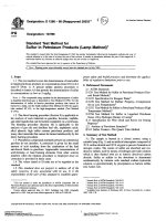
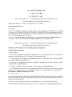
See Fig. 1 and Fig. 2 for general views of the engine and
attached apparatus used in this test method.
6.3.1 Do not use heat lamps or fans directed at the engine,
and do not use insulation on the engine, for temperature
control.
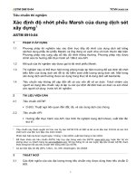
6.4 Test Engine—The test engine is a 1986–87 3.8-L (231in.3) V-6 engine21 with an 8.0:1 compression ratio, equipped
with the specified two-barrel carburetor. See Fig. 3. (Procure
the block for this engine from the recommended source.19)
Rebuild the engine as specified in this test method.
6.4.1 Engine Parts—Use the engine parts included in Annex A2 and Annex A3.
6.4.1.1 Use all engine parts as received from the supplier,
either the Central Parts Distributor or an original equipment
manufacturer dealer24 unless modifications are specified in this
test method, or unless defects in the parts require that they be
returned to the supplier.
6.4.1.2 Do not divert to other applications, any parts obtained for use in Sequence IIIE testing.
6.4.1.3 Before disposing of Sequence IIIE engine parts,
render them useless for automotive engine applications.
6.4.1.4 Use serialized engine bearing kits; do not substitute
other bearings.
6.4.2 Hold-Back Fixture—Use the hold-back fixture shown
in drawing RX-118641-A2 to restrict axial movement of the
camshaft. See Fig. 4.
engine oils for protection against oil thickening and engine
wear during high-speed, high-temperature service.
5.2 The increase in oil viscosity obtained in this test
indicates the tendency of an oil to thicken because of oxidation.
In automotive service, such thickening can cause oil pump
starvation and resultant catastrophic engine failures.
5.3 The deposit ratings for an oil indicate the tendency for
the formation of deposits throughout the engine, including
those which can cause sticking of the piston rings in their
grooves, and the sticking of plungers in hydraulic valve lifters.
The former can be involved in the loss of compression
pressures in the engine, and the latter is related to valve train
noise and wear.
5.4 The camshaft and lifter wear values obtained in this test
provide a measure of the anti-wear quality of an oil under
conditions of high unit pressure mechanical contact.
5.5 The test method was developed to correlate with field
experience using oils of known good and poor protection
against oil thickening and engine wear.23
5.6 The Sequence IIIE engine oil test is used in specifications and classifications of engine lubricating oils, such as the
following:
5.6.1 Specification D 4485,
5.6.2 Military Specification MIL-L-2104, and
5.6.3 SAE Classification J 183.
6. Apparatus
6.1 Laboratory—Observe the following laboratory conditions to ensure good control of test operations, and good
repeatability:
6.1.1 Maintain the ambient laboratory atmosphere relatively
free of dirt, dust, and other contaminants.
6.1.2 Control the temperature of the room in which parts
measurements are made so that the temperature for after-test
measurements is within a range of 63°C (65°F) relative to the
temperature for the before-test measurements. If difficulties
with parts fits are encountered, consider the effects of temperature coefficient of expansion. See 6.2.
6.1.3 Filter the air in the engine build-up area, and control
its temperature and humidity to prevent accumulation of dirt or
rust on engine parts.
6.1.4 If an engine is assembled in an area of controlled
environment and moved to a non-controlled area, provide
suitable protection of the engine so that moist air cannot enter
the engine and promote rusting before the test.
6.1.5 Do not permit air from fans or ventilation systems to
blow directly on an engine mounted on a test stand.
6.2 Drawings—Obtain the equipment drawings referenced
in Annex A3 of this test method from the ASTM TMC.
Because the drawings may not be to scale, when using them to
fabricate special parts, use the dimensions specified. Do not use
a drawing as a pattern. Drawing dimensions are considered to
be correct when the temperature of the equipment is 22°C
(72°F), unless otherwise specified.
6.3 Specified Equipment—Use the equipment specified in
the procedure whenever possible. Substitution of equivalent
6.5 Engine Speed and Load Control— Use dynamometer
speed and load control systems with which the speed and
power limits specified in Section 12 can be maintained.
6.6 Engine Cooling System—Use an external engine cooling system, such as shown in drawing RX-116681-D, to
maintain the specified engine coolant temperature during both
the operating and the shutdown portions of the test. The system
must incorporate the following features:
6.6.1 No pressurization,
6.6.2 Coolant flow rate of 151 6 3.8 L/min (406 1
gal/min),
6.6.3 Capacity of 85.2 6 9.5 L (22.5 6 2.5 gal),
6.6.4 A sharp-edge orifice meter, utilizing a 50.8-mm (2.0in.) orifice plate, such as that shown in drawings RX-116645-D
through RX-116650-D and RX-119051-A318,20 for the measurement of coolant flow rates,
6.6.5 A system to control the coolant flow rate, such as that
shown in drawing RX-117161-C,21 and
6.6.6 Low-point drains to ensure draining all of the flushing
water prior to installing a fresh glycol mixture.
6.7 Flushing Tank—Use a flushing tank such as that shown
in drawings RX-116924-C, RX-117230-E, and RX-117231-C
to circulate the cleaning agents. Use plumbing materials which
are impervious to the acidic cleaning agents (stainless steel has
23
Bergin, S. P., and Smolenski, D. J., “Development of the ASTM Sequence IIIE
Engine Oil Oxidation and Wear Test,” SAE 881576.
24
Some of the engine parts are available from local General Motors dealers. See
Table A2.3.
NOTE 2—RX and BX drawings referenced in this test method are listed
in Annex A3.
6
NOTICE: This standard has either been superceded and replaced by a new version or discontinued.
Contact ASTM International (www.astm.org) for the latest information.
D 5533
FIG. 1 Sequence IIIE Test Engine and Attached Apparatus—View 1
been found satisfactory).
6.8 Coolant Mixing Tank—Use a mixing tank such as that
shown in drawing RX-117350-D to premix the engine coolant.
6.9 Jacketed Rocker Cover, Intake Manifold Crossover, and
7
NOTICE: This standard has either been superceded and replaced by a new version or discontinued.
Contact ASTM International (www.astm.org) for the latest information.
D 5533
FIG. 2 Sequence IIIE Test Engine and Attached Apparatus—View 2
Breather Tube Cooling Systems—Provide external cooling
systems, one for the rocker covers (non-production parts) and
intake manifold crossover, and one for the breather tube. Use
8
NOTICE: This standard has either been superceded and replaced by a new version or discontinued.
Contact ASTM International (www.astm.org) for the latest information.
D 5533
FIG. 3 Sequence IIIE Test Engine Carburetor
to maintain the specified oil temperature. The system consists
of a positive displacement pump18,25 that delivers a flow of
21.8 6 0.95 L/min (5.75 6 0.25 gpm) at 1140 r/min, no relief
valve, calibrated with build-up oil18,20 at 29.4 6 0.6°C (85 6
1°F) as shown in drawing RX-116680-C, a linear control
valve,18,26 and heat exchanger Part BX-350-1.18,20 See Fig. 5.
6.10.1 Check the condition of the positive displacement
pump for the following:
6.10.1.1 The flow rate must be that shown in drawing
RX-116680-C.
6.10.1.2 The speed must be 1140 6 20 r/min under Sequence IIIE operating conditions.
pumps, flowmeters, plumbing connections, and heat exchangers such as shown in drawings BX-350-1, RX-117290-C,
RX-117731-C, and RX-118615-E to maintain the specified
operating conditions. The systems must incorporate the following features:
6.9.1 For the rocker covers and intake manifold crossover
system, a pump and flowmeter with which engine coolant can
be supplied at 113 6 2.8°C (235.4 6 5°F) and 11.4 6 3.8
L/min (3 6 1 gpm) [5.7 6 1.9 L/min (1.5 6 0.5 gpm) per
rocker cover].
6.9.1.1 Provisions for maintaining the rocker cover coolant
pressure at 27.5 6 6.9 kPa (4.0 6 1.0 psi).
6.9.2 For the breather tube system, a pump and flowmeter
with which coolant can be supplied at 40 6 1.1°C (104 6
2.0°F) and 11.4 6 3.8 L/min (3 6 1 gpm).
6.9.2.1 Provisions for maintaining the breather tube coolant
outlet pressure at 27.5 6 6.9 kPa (4.0 6 1.0 psi).
6.9.3 For each of the two systems, low-point drains to allow
for removal of all coolant.
6.10 External Oil-Cooling System—Incorporate an external
oil-cooling system, such as shown in drawing RX-116680-C,
25
An oil pump that has been found suitable for this application is Viking Model
G4125, 21.8 6 0.95 L/min (5.75 6 0.25 gal/min) at 1140 r/min, with 0.13 mm
(0.005 in.) rotor to end plate clearance, no relief valve. It is available through local
Viking distributors or Houdaille Industries, Inc., Viking Pump Division, George and
Wyeth Sts., Cedar Falls, IA 50613.
26
An oil control valve that has been found suitable is Part 2735, type 75S 3W,
trim A linear control valve available from Badger Meter Inc., Precision Products
Div., 6116 E. 15th St., Tulsa, OK 74112.
9
NOTICE: This standard has either been superceded and replaced by a new version or discontinued.
Contact ASTM International (www.astm.org) for the latest information.
D 5533
FIG. 4 Sequence IIIE Test Engine Disassembled Camshaft Hold-Back Fixture
times to purge all air from the system. Turn off oil pump.
Firmly insert rubber stopper or screw 1⁄2-in. NPT plug in pan
outlet fitting at bottom of pan to keep oil lines filled with
aliphatic naphtha when the pan is drained. Drain aliphatic
naphtha remaining in the pan using the pan drain valve,
manually scraping any residual aliphatic naphtha into the drain
using a plastic scraper. Measure the weight of the removed
aliphatic naphtha and subtract from the initial weight (less the
weight of the container). Repeat the above process until the
weight measurement repeats within 4 % (equivalent to 30 mL
(1 oz) volume of aliphatic naphtha). Determine if the external
oil system meets the test specification of 739 6 59 mL (25 6
2oz). If necessary, adjust length of oil lines or fitting size to
obtain the required volume and recheck system volume using
the above procedure. Note that the system flow rate shall be
rechecked when any component is replaced.
6.10.2 Do not use cuprous lines or fittings in the oil-cooling
system.
6.10.3 Do not use magnetic plugs in the oil-cooling system.
6.10.4 Install suitable fittings in the engine oil pan, as shown
in drawing RX-118626-A1, to accommodate the oil lines.
6.10.5 Use minimum-length oil lines to the heat exchanger
and valve(s) in order that the total external oil volume,
including that of the oil in the lines, heat exchanger, valves,
pump, and sensing elements, is 739 6 59 mL (25 6 2 oz).
6.10.6 Use suitable hose and fittings when plumbing the
oil-cooling system.18,27
6.10.7 If quick disconnect-type fittings are installed, use
only the straight-through type, such as those shown in drawings RX-116680-C and RX-118618-C.
6.10.7.1 Maintain all couplings, O-rings, and hoses to minimize air leaks on the suction side.
6.10.8 Prior to each reference oil test or after any system
component, except external heat exchanger or heat exchanger
core, is replaced, the volume and flow rate of the external oil
system should be verified according to the following procedures:
6.10.8.1 Clean the external oil system and air blow dry (see
10.1). Connect oil lines to a calibration oil pan firmly mounted
at engine height. A drain valve should be installed in place of
the drain plug or at the lowest point of the pan. The pan outlet
fitting should be capable of being plugged with a rubber
stopper or modified with a 1⁄2-in. NPT thread. Weigh, at room
temperature, 4320 mL (146 oz) of aliphatic naphtha (see 7.4) (
Warning—see Note 3) with a boiling point greater than 149°C
(300°F) to determine the weight per volume (grams/mL).
Carefully add aliphatic naphtha to oil pan. Operate oil pump
alternately one minute on and one minute off while cycling the
three-way control valve. Repeat cycling of the pump several
NOTE 3—Warning: Combustible. Health Hazard.
6.10.8.2 Clean the external oil system and air blow dry (see
10.1). Connect oil lines to calibration oil pan firmly mounted at
engine height. Insert a calibrated flow meter in oil return line.
Use a flow meter18,28 with minimum pressure drop and
restriction to flow. The flow meter should be calibrated using
build-up oil at 29.4°C (85°F). Observe typical 103 diameter
straight pipe rule before and after meter to reduce flow
disturbance. Add 4320 mL (146 oz) of build-up oil18 to the oil
pan. Operate oil pump while cycling the three-way control
valve to purge air from the system (excessive air in oil will
cause erroneous flow measurement, particularly with turbine
meters). With the three-way control valve set at 50 %, record
flow rate when reading has stabilized and the oil temperature
measures 28.9 to 30.0°C (84 to 86°F) on sump thermocouple.
Determine if the oil system meets test specified flow rate of
21.8 6 0.95 L/min (5.756 0.25 gpm). If necessary, adjust
pump clearance or replace pump, then recheck flow rate using
the above procedure.
27
A hose which has been found suitable for most of the system is polytetrafluoroethylene 2807-8 [11 mm (0.43 in.) inside diameter]. For the oil pan-to-pump inlet
line, use polytetrafluoroethylene 2807-10 [13 mm (0.51 in.) inside diameter]. Such
types of hose and suitable fittings can be obtained from Aeroquip Corp., Industrial
Division, 1225 W. Main St., Van Wert, OH 45891.
28
A Cox Model AN10 Turbine Meter has been found suitable and can be
obtained from local suppliers of Cox products.
10
NOTICE: This standard has either been superceded and replaced by a new version or discontinued.
Contact ASTM International (www.astm.org) for the latest information.
D 5533
FIG. 5 Sequence IIIE Test Engine External Oil-Cooling System
tent and temperature of the carburetor air. Maintain the air
supply duct surface temperature above the dew point to prevent
condensation.
6.12.2 Use a method of controlling the flow of air, and
thereby the air pressure, to the carburetor such as that shown in
drawing RX-117162-C. Use carburetor inlet adapters and
gaskets such as shown in drawings BX-395-1 and RX118616-E, as well as gasket BX-361-1, respectively. See Fig. 6.
Position the adapter so that the air enters the adapter from the
left rear of the engine. Remove the humidified air supply from
the carburetor when the engine is not running; leave it
disconnected for the timing run.
6.13 Temperature Measurement—Use iron-constantan
(Type J) thermocouples or platinum resistance thermocouples
for temperature measurement.18,32 Other temperature sensors
that give the same results may be used, provided that they are
approved by the ASTM TMC.
6.11 Fuel System—Use a pressurized fuel system, including
a pressure regulator,18,29 to provide 28 6 7 kPa (4 6 1 psi) fuel
pressure at the carburetor. Incorporate shutoff valves18,30 in the
system so that no fuel pressure is present at the carburetor
during engine shutdowns.
6.12 Carburetor Air Supply Humidity, Temperature, and
Pressure—Maintain the carburetor intake air at a moisture
content of 11.4 6 0.7 g/kg of dry air (80.0 6 5 grains/lb of dry
air),18,31 a dry bulb temperature of 27 6 1.5°C (80.6 6 2.7°F),
and a static pressure of 0.050 6 0.025 kPa (0.2 6 0.1 in. of
water) measured at the carburetor inlet.
6.12.1 Use a system such as that shown in drawings
RX-117375-C and RX-117376-C to control the moisture con29
A fuel pressure regulator which has been found suitable can be obtained from
Fisher Governor Co., 1900 Fisher Building, Marshalltown, IA 50158.
30
A fuel shut-off valve which has been found suitable is Part X5D30280, which
can be obtained from Skinner Precision Industries, Inc., Skinner Electric Valve
Division, 95 Edgewood Ave., New Britain, CT 06050.
31
A humidity-measuring device which has been found suitable is the Alnor 7300
Dewpointer, without radium source, which is available through local distributors or
Alnor Instrument Co., 7555 N. Linden Ave., Skokie, IL 60077.
32
Thermocouples and packing glands (Part MPG-125-A-T) which have been
found suitable are obtainable from Conax Corp., 2300 Walden Ave., Buffalo, NY
14225.
11
NOTICE: This standard has either been superceded and replaced by a new version or discontinued.
Contact ASTM International (www.astm.org) for the latest information.
D 5533
FIG. 6 Sequence IIIE Test Engine Carburetor Inlet Adapters and Breather Tube
6.13.1 Thermocouple Location—Locate the sensing tip of
all thermocouples in the center of the stream of the medium
involved, unless otherwise specified.
12
NOTICE: This standard has either been superceded and replaced by a new version or discontinued.
Contact ASTM International (www.astm.org) for the latest information.
D 5533
6.13.1.1 Oil Filter Adapter—Install the thermocouple18,33
in the tapped hole in the oil filter adapter, as shown in drawing
RX-118613-C. See Fig. 7.
6.13.1.2 Oil Pan (Sump)—Install the thermocouple18,34 in
the oil sump as shown in drawing RX-118626-A, with the tip
extending 38 mm (1.5 in.) into the oil pan. See Fig. 8. [The oil
temperature indicated at this point is generally within 1.5°C
(2.7°F) of the temperature measured at the filter adapter.]
6.13.1.3 Engine Coolant In—Install the thermocouple18,33
in the coolant inlet adapter as shown in drawing RX-118608-D.
See Fig. 9.
6.13.1.4 Engine Coolant Out—Install the thermocouples18,33 for the coolant outlets as shown in drawing
RX-118609-A1. See Fig. 10.
6.13.1.5 Intake Manifold Mixture—Install the thermocouple18,33 using a reducer in the 1⁄4-in. NPT hole located on
the No. 6 cylinder leg of the intake manifold as shown in
drawing RX-118615-E. See Fig. 11.
6.13.1.6 Rocker Cover Coolant Out—Locate the thermocouple18,35 for each rocker cover within 76 mm (3 in.) of the
coolant-out fitting in the cover.
6.13.1.7 Intake Manifold Crossover Coolant Outlet—Install
the thermocouple18,35 as specified in drawing RX-118615-E.
6.13.1.8 Breather Tube Coolant Out—Locate the thermocouple18,33 within 76 mm (3 in.) of the coolant-out fitting in the
breather tube.
6.13.1.9 Blowby Gas—Install the thermocouple18,33 at the
outlet of the breather tube, through which the blowby gas
flows. Locate the thermocouple tip at the center of the outlet.
6.13.1.10 Fuel—Install the thermocouple18,35 in a tee fitting
in the fuel line within 51 mm (2 in.) of the carburetor fuel inlet.
6.13.1.11 Carburetor Air—Install the thermocouple18,33 as
shown in drawing BX-395-1. See Fig. 6.
6.13.1.12 Ambient Air—Install the thermocouple18,35 approximately 76 mm (3 in.) directly below the external oil
system return line oil pan fitting.
6.14 Air-to-Fuel Ratio Determination— Determine the engine air-to-fuel ratio by measuring the CO, CO2, and O2
components of the exhaust gas sample with either an Orsat
apparatus36 or electronic exhaust gas analysis equipment.18,37
When using electronic exhaust gas analyzers, take particular
care to ensure that the exhaust gas sample is dried prior to
introducing it to the analyzer. Take the exhaust gas samples
from the top holes of the exhaust manifold exit flanges.
6.15 Exhaust and Exhaust Back Pressure Systems:
6.15.1 Exhaust Manifolds and Pipes—Install water-cooled
exhaust manifolds18,38 as shown in drawing RX-118614-D (see
Fig. 12), using 102-mm (4-in.) stainless steel exhaust pipe,18,39
immediately prior to charging the engine with test oil. Orient
the manifolds so that the exhaust exits the manifolds at either
the rear or front of the engine.
6.15.2 Water-Jacketed Exhaust Pipes—If a test laboratory
chooses to use either jacketed exhaust pipes or external water
spray, they must be applied on the portions of the exhaust
system extending below the test bed or floor level. Do not use
water-jacketed exhaust pipes on the sections of exhaust pipe
extending from the exhaust manifold to the test bed or floor
level. Do not apply an external water spray to the exhaust pipes
above the test bed or floor level. Do not introduce cooling
water into the exhaust streams at any point of the exhaust
system.
6.15.3 Exhaust Sample Lines—Install exhaust sample lines
at the top holes of the two exhaust manifold exit flanges. Do
not interconnect these lines; they are used to take samples from
each bank for air-to-fuel ratio determinations.
6.15.4 Back-Pressure Lines—To permit measurement of the
back pressure in each exhaust manifold, install exhaust backpressure lines from the bottom holes of the exhaust manifold
exit flanges (location shown in drawing RX-118614-D) to traps
located ahead of the manometers. Orient the lines so that any
liquid accumulating in them will drain to the traps. Retain
about 20 mm (3⁄4 in.) of liquid in the traps to ensure that closed
systems exist.
6.16 Blowby Flow Rate Measurement System
6.16.1 Use the sharp-edge orifice meter shown in drawing
RX-116169-C to measure engine blowby flow rates. Connect
the meter to a surge tank (drawing RX-117431-C) and to other
33
A thermocouple which has been found suitable is Conax J-SS-12-G-PG 76
mm (3 in.).
34
A thermocouple which has been found suitable is Conax J-SS-12-G-PG 51
mm (2 in.).
35
A thermocouple which has been found suitable is Conax J-SS-G-12-G-PG 51
mm (2 in.).
36
Orsat analysis apparatus is commercially available.
An electronic exhaust gas analyzer which has been found suitable is Horiba
MEXA 554GE, available from Horiba Instruments, Inc., 1021 Duryea Ave., Irvine
Industrial Complex, Irvine, CA 92714.
38
A water-cooled exhaust manifold which has been found suitable is Barr
Marine Part BV6-1-75, available from Barr Marine Products Co., 1505 Ford Rd.,
P.O. Box 408, Cornwells Heights, PA 19020.
39
Stainless steel exhaust pipe which has been found suitable is Flexonic Part RT
10E, available from local distributors or Flexon Industries, 666 Washington Ave.,
Belville, NJ 07109.
37
FIG. 7 Sequence IIIE Test Engine Oil Filter Adapter
13
NOTICE: This standard has either been superceded and replaced by a new version or discontinued.
Contact ASTM International (www.astm.org) for the latest information.
D 5533
FIG. 8 Sequence IIIE Test Engine Oil Pan
5 kPa (1 psi). Connect the gage to the location shown in
drawing RX-118613-C.
6.17.3 Oil Pump Outlet Pressure—Use a gage having a
range of 0 to 700 kPa (0 to 100 psi) and scale graduations of
5 kPa (1 psi). Connect the gage to the location shown in
drawing RX-118613-C.
6.17.4 Rocker Cover Coolant Pressure— Use a pressure
gage having a range of 0 to 100 kPa (0 to 15 psi) and scale
graduations of 5 kPa (1 psi). Measure the pressure at the top
front coolant-outlet fitting of each rocker cover as described on
drawing RX-118615-E.
6.17.5 Breather Tube Coolant Pressure— Use a pressure
gage having a range of 0 to 100 kPa (0 to 15 psi) and scale
graduations of 5 kPa (1 psi). Connect the gage to the coolantoutlet fitting of the breather tube as shown in drawing
RX-118615-E.
6.17.6 Exhaust Back Pressure—Use either a manometer or
pressure gage having a range of 0 to 10 kPa (0 to 40 in. of
water) and scale graduations of 25 Pa (0.1 in. of water).
Connect the manometer or gage to the bottom holes of the
exhaust manifold exit flanges as shown in drawing RX118614-D.
6.17.7 Carburetor Inlet Air Pressure— Use either a manometer or a pressure gage having a range of 125 Pa (0.5 in. of
water) and scale graduations of 5.0 Pa (0.02 in. of water). If a
manometer is used, install a condensate trap between the
manometer and the carburetor inlet adapter to protect against
the possibility of momentary interruption of air flow or any
other transient condition that might result in manometer fluid
entering the engine intake system. Connect the manometer or
equipment shown in drawings RX-117726-C, RX-117727-C,
RX-117294-A, and RX-117729-C.
6.16.2 Mount the meter in a horizontal position with a
minimum blowby gas inlet line straight run length of 15 cm (6
in.) upstream and 8 cm (3 in.) downstream. All bends in the
blowby gas inlet and outlet lines shall be large enough in radius
to eliminate reduction of inside diameters. Although the
orientation of the orifice meter has no influence on the blowby
measurement, within 6 1.0 % of the volume read over a range
of 7.1 to 141.6 L/min (0.25 to 5.0 ft3/min), it could have an
influence on entrained contaminant accumulations deposited
on the orifice plate surfaces.
6.16.3 Keep the blowby gas inlet line length from the
breather tube to the blowby cart to a minimum. Shorter line
lengths will reduce line losses, contaminant accumulations, and
excessive temperature losses between the breather tube and the
orifice plate.
6.17 Pressure Measurement and Pressure Sensor
Location—Use pressure sensors such as pressure gages or
manometers, or electronic transducers, located as indicated,
and following the established guidelines:40
6.17.1 Intake Manifold Vacuum—Use either a manometer
or a vacuum gage having a range of 0 to 100 kPa (0 to 20 in.
Hg) and scale graduations of 0.5 kPa (0.1 in. Hg). Connect the
manometer or gage to the 1⁄8 in. NPT hole located at the rear of
the carburetor base as shown in drawing RX-118617-E.
6.17.2 Engine Oil Gallery Pressure—Use a gage having a
range of 0 to 700 kPa (0 to 100 psi) and scale graduations of
40
See the 1987-04-02 Instrumentation Task Force Report to the ASTM Committee D02.B0.08 Technical Guidance Committee.
14
NOTICE: This standard has either been superceded and replaced by a new version or discontinued.
Contact ASTM International (www.astm.org) for the latest information.
D 5533
FIG. 10 Sequence IIIE Test Engine Coolant Outlet Adapter
7.1.1 Make certain that all tanks used for transportation and
storage are clean before they are filled with test fuel.
7.1.2 Verify that at least 1420 L (375 gal) of test fuel
(Warning—see Note 4) is available for use before initiating a
test.
7.2 Additive Concentrate for the Coolant—Blend the additive concentrate for the engine coolant system, and for the
rocker cover and breather tube coolant system, using ethylene
glycol 18,43 meeting Specification E 1119 (Warning—see Note
5) plus the coolant additive18,44 at a concentration of 15.625
mL/L (0.125 pt/gal) (Warning—see Note 6).
FIG. 9 Sequence IIIE Test Engine Coolant Inlet Adapter
NOTE 5—Warning: Combustible. Health Hazard.
NOTE 6—Warning: See the appropriate materials safety data sheet.
gage to the carburetor air inlet adapter as shown in drawing
BX-395-1.
6.17.8 Crankcase Pressure—Use a gage or manometer
having a range of − 125 to + 125 Pa (−0.5 to + 0.5 in. of water)
and scale graduations no greater than 5.0 Pa (0.02 in. of
water).18,41
6.17.8.1 If a manometer is utilized in this application, install
a condensation trap to eliminate the possibility of manometer
fluid accidentally entering the crankcase.
6.17.8.2 Connect the gage or manometer to the location
shown in drawing RX-118633-A3.
6.17.8.3 Do not apply any external means at the breather
tube to influence the crankcase pressure reading.
7.3 Coolant Preparation—Prepare the coolant blend for the
engine coolant system, and for the rocker cover and breather
tube coolant system, in the following manner:
7.3.1 Do not apply heat either during, or following, the
coolant preparation.
7.3.2 Use a container of a size adequate to hold the entire
coolant blend required by both systems. See drawing RX117350-D for an example of a suitable container.
7.3.3 Add the required amount of glycol ( Warning—see
Note 5) to the container.
7.3.4 Add the required amount of additive concentrate to the
container.
7.3.5 Agitate the blend in the container for 30 min.
7.3.6 Within 2 h, add the blend to the engine coolant system,
and to the rocker cover and breather coolant system.
7.4 Pre-Test Cleaning Materials—Use the cleaning materials (see Note 7) specified in the following list for cleaning of
7. Reagents and Materials
7.1 Test Fuel—Use only fuel from approved batches of
GMR 995 test fuel18,42 (Warning—see Note 4) (see Annex A4,
Table A4.1), observing the following:
NOTE 4—Warning: Flammable. Health Hazard.
43
Ethylene glycol meeting this specification is available from Dow Chemical
Co., 2040 Dow Center, Midland, MI 48674.
44
Pencool 2000 Coolant Additive is required for use in the Sequence IIIE test.
The Pencool 2000 Coolant Additive can be obtained from The Penray Cos., Inc.,
1801 Estes Ave., Elk Grove, IL 60007.
41
A gage which has been found suitable is Magnehelic Gauge Model No. 2301
available from Dwyer Instrument Co., P.O. Box 373, Michigan City, IN 46360.
42
Sequence IIIE test fuel (GMR-995) from approved batches can be ordered
from Phillips 66 Co., Philter Marketing Service, P.O. Box 968, Borger, TX 79008.
15
NOTICE: This standard has either been superceded and replaced by a new version or discontinued.
Contact ASTM International (www.astm.org) for the latest information.
D 5533
FIG. 11 Sequence IIIE Test Engine Intake Manifold
parts to be used in the test. Use no substitutes (see Note 8).
7.4.1 Commercial cleaning agent18 ,45 (see Note 9),
7.4.2 Petroleum ether18,46 (see Note 10),
7.4.3 Aliphatic naphtha meeting Specification D 235 Type I
regular mineral spirits (Stoddard solvent) requirements, with a
boiling point of 149–204°C (300–400°F)46 (see Note 3), and
7.4.4 Sequence IIIE test component cleaner,18 ,47 a mixture
(by mass) of:
94 parts oxalic acid18,48 (see Note 11)
6 parts dispersant18,49 (see Note 11).
lency must be proven and approval obtained from the ASTM TMC.
NOTE 9—Warning: Corrosive. Health Hazard.
NOTE 10—Warning: Flammable. Health Hazard.
NOTE 11—Warning: Corrosive. Health Hazard.
NOTE 7—Warning: See the appropriate materials safety data sheet.
NOTE 8—Only these specific materials and sources have been found
satisfactory. If chemicals other than these are proposed for use, equiva-
7.5.1.1 99.5 + % THF,
7.5.1.2 Inhibited with 0.025 % BHT, and
7.5.1.3 Less than 0.03 % water.
7.6 Sealing and Anti-seize Compounds— Use the sealing
and anti-seize compounds specified in the following list. See
Note 13 and Note 14.
7.6.1 Sealing compound for the intake port areas of the
intake manifold gasket,18,51
7.5 Post-Test Cleaning Materials—Blend the solvent as
specified in Table 1, which is used as a rating aid.
7.5.1 The tetrahydrafuran18,50 (THF) (see Note 15) used
shall meet the following specifications:
NOTE 12—Warning: The THF should be inhibited by butylated hydroxytoluene (BHT) so that explosive hazards upon drying are limited.
45
The commercial cleaning agent, Oakite 811, and the Oakite Parts Cleaner,
have been found suitable. They are available from Oakite Products, Inc., 50 Valley
Rd., Berkley Heights, NJ 07922.
46
Petroleum ether and aliphatic naphtha are available from local petroleum
product suppliers.
47
The blended cleaner has been found suitable. It is available from Wrico Corp.,
4835 Whirlwind, San Antonio, TX 78217.
48
Oxalic acid (55-lb bags) and sodium carbonate (50-lb bags) are available from
Ashland Chemical Co., P.O. Box 391, Ashland, KY 41114. If permitted by the
hazardous materials disposal practices in a laboratory, sodium carbonate can be used
to neutralize the oxalic acid in used Sequence IIIE Test component cleaner.
49
Petro Dispersant Number 425 Powder (50-lb bags) is available from Witco
Corp., 3230 Brookfield, Houston, TX 77045.
50
Tetrahydrafuran which has been found suitable is THF, catalog number
14722-2, available from Aldrich Chemical Company, Inc., 1001 W. St. Paul Ave.,
Milwaukee, WI 53233.
51
Perfect Seal Number 4 Brush-Type Sealing Compound, Part GM3D (16-oz
container), must be used. It can be ordered from P.O.B. Sealants Inc., 11102
Kenwood Rd., Cincinnati, OH 45242.
16
NOTICE: This standard has either been superceded and replaced by a new version or discontinued.
Contact ASTM International (www.astm.org) for the latest information.
D 5533
FIG. 12 Sequence IIIE Test Engine Water-Cooled Exhaust Manifolds
7.6.2 Sealing compound for the rear main seal,18 ,52
7.6.3 Non-hardening sealing compound for the water ports
of the intake manifold gasket,18,53
TABLE 1 Post-Test Cleaning MaterialsA
Component
Ethyl acetateB
Denatured alcohol (No. 30)C
Butyl alcoholD
TetrahydrofuranB
Volume %
37.5
27.5
5.0
30.0
52
Loctite Superbonder 414 has been found suitable. It is available from local
distributors of Permatex products, or can be found by contacting Permatex
Company, Inc. (Loctite Corporation), 18731 Cranwood Parkway, P.O. Box 7138,
Cleveland, OH 44128-7138.
53
Permatex Number 2 non-hardening sealer for the water ports, and cylinder
head bolts, have been found suitable. They are available from local distributors of
Permatex products, or they can be found by contacting Permatex Company, Inc.
(Loctite Corporation), 18731 Cranwood Parkway, P.O. Box 7138, Cleveland, OH
44128-7138.
A
Only the specific materials indicated in Table 1 have been found satisfactory.
No other chemicals may be used.
B
Note 1—WARNING—See the appropriate materials safety data sheet.
C
Note 2—WARNING—Flammable. Denatured alcohol cannot be made nontoxic. Health Hazard.
D
Note 3—WARNING—Flammable. Health Hazard.
Note 4—WARNING—Flammable. Health Hazard.
17
NOTICE: This standard has either been superceded and replaced by a new version or discontinued.
Contact ASTM International (www.astm.org) for the latest information.
D 5533
7.6.4 Sealing compound for the cylinder head bolts,18,53
7.6.5 Anti-seize compound for the exhaust manifold and
pipe bolts,18,54
7.6.6 High-temperature silicone sealer for use as substitute
for rear main bearing cap side seals,18,55
7.6.7 Weather-strip adhesive for the rocker arm cover
gaskets, and18,56
7.6.8 Perfect Seal No. 4 Aerosol Spray Gasket Sealing
Compound, Part No. GM3MA18,57, is specified for the cylinder
head gaskets.
8.4.6 Install suitable guards around all external moving
parts, or hot parts.
8.4.7 Advise personnel not to work alongside the engine
and coupling shaft when the engine is operating at high speeds.
8.4.8 Provide barrier protection between the engine and
coupling shaft, and operating personnel.
8.4.9 Prohibit the wearing of loose or flowing clothing by
personnel working near a running engine.
8.4.10 Advise personnel regarding the possibility of exothermic reactions with some of the chemicals used in the
Sequence IIIE test.
8.5 Safety Equipment and Practices— Observe the following in order to establish and maintain safe working conditions
for Sequence IIIE testing:
8.5.1 Provide the proper tools for conducting the Sequence
IIIE test.
8.5.2 Require regular inspection and approval by the laboratory safety department of the facilities used for Sequence IIIE
testing.
8.5.3 Properly install all fuel lines, oil lines, and electrical
wiring; and maintain them in good condition.
8.5.4 Select and install coolant hoses and clamps with
special care in order to prevent coolant leaks and possible fires.
8.5.5 Do not permit tripping hazards to exist in any of the
areas involved with the Sequence IIIE testing.
8.5.6 Keep the outer surfaces of the engine, other equipment, and the floor area free of fuel and oil.
8.5.7 Do not allow the accumulation of containers of oil or
fuel in Sequence IIIE test areas.
8.5.8 Demand that personnel be alert for leaking fuel,
exhaust gas, oil, or coolant, and that they take action to stop
such leaks.
8.5.9 Equip the test stand with an automatic fuel shutoff
valve designed to turn off the fuel supply to the engine
whenever the engine is not running.
8.5.10 Make provision for manual, remote operation of the
fuel shutoff valve.
8.5.11 Install suitable interlocks to shut down the engine
when any of the following develop: loss of dynamometer field
current, engine overspeeding, loss of engine oil pressure,
failure of the exhaust system, failure of the room ventilation,
activation of the fire protection system, excessive vibration,
etc.
8.5.12 In case of injury, seek medical attention immediately,
and report the incident to the proper administrative people.
NOTE 13—Warning: See the appropriate materials safety data sheet.
NOTE 14—Except for the high-temperature silicone sealer, only the
specific materials and sources indicated in 7.6 have been found satisfactory. If materials other than these are proposed for use, equivalency must
be proven and approval obtained from the ASTM TMC.
8. Hazards
8.1 General—The environment involved with any engine
test is inherently hazardous. Serious injury of personnel and
damage to facilities can occur if adequate safety precautions
are not taken. However, as evidenced by the fact that many
thousands of engine tests are successfully conducted each year,
it is possible to take adequate precautions.
8.2 Caveat—The following paragraphs do not cover all
possible safety-related problems associated with Sequence IIIE
testing. See 1.3.
8.3 Personnel—Carefully select and train personnel who
will be responsible for the design, installation, and operation of
Sequence IIIE test stands. Make certain that the test operators
are capable of handling the tools and facilities involved, and in
observing all safety precautions, including avoiding contact
with either moving or hot test parts.
8.4 Personnel Protection Facilities— Provide the following
personnel protection facilities:
8.4.1 Provide safety shower and eye-rinse equipment in
close proximity to the facilities used for parts cleaning, engine
build-up, engine test operation, and parts rating.
8.4.2 Provide, and require the use of, appropriate face
masks, eye protection, chemical breathers, gloves, etc. in all
aspects of Sequence IIIE testing.
8.4.3 Provide dry chemical fire extinguishers for putting out
fires.
8.4.4 Advise personnel not to use water to attempt to
extinguish fires involving fuel, oil, or glycol.
8.4.5 Equip test stands with automatic fire extinguishing
equipment.
9. Test Oil Sample Requirements
9.1 Selection—The supplier of the test oil sample shall
determine that it is representative of the lubricant formulation
being evaluated and that it is not contaminated.
9.2 Quantity—The supplier shall provide approximately 15
L (4 gal) of the test oil sample.
54
Anti-seize compounds which have been found suitable are Fel-Pro C-100,
available from Fel-Pro, Inc., 7450 N. McCormick Blvd., Skokie, IL 60076 and
Permatex anti-seize compound [Part 80078 (133K) 8-oz brush-top container],
available from local distributors of Permatex products. It can also be found by
contacting Permatex Company, Inc. (Loctite Corporation), 18731 Cranwood Parkway, P.O. Box 7138, Cleveland, OH 44128.
55
GM high-temperature silicone sealer, Part 12346193 or 12346192, available
from General Motors dealers, has been found suitable.
56
Use only 3M Super Weather-Strip Adhesive, part number 051135-08001
available from Minnesota Mining and Manufacturing Co., AC & S Division,
Department TR, 3M Center, 223-6 N.E., St. Paul, MN 55144-1000.
57
The sole source of supply of the supply of the sealant known to the committee
at this time is P.O.B. Sealants Inc., 11102 Kenwood Rd., Cincinnatti, OH 45242.
NOTE 15—A Sequence IIIE Test can be conducted with only 10.5 L
(2.75 gal) of test oil, provided that no spillage or leakage occurs during
test preparation. The greater quantity is specified to accommodate such
spillage and leakage.
9.3 Storage Prior to Test—The test laboratory shall store the
test oil sample in a covered building to prevent contamination
by rainwater.
18
NOTICE: This standard has either been superceded and replaced by a new version or discontinued.
Contact ASTM International (www.astm.org) for the latest information.
D 5533
abrasive cloth59. Rinse with warm water.
10.3.3 Spray with a 50/50 mixture of aliphatic naphtha/
build-up oil (Warning—see Note 3).
10.3.4 Every ten runs, or more frequently if necessary, clean
the coolant passages with nitric or muriatic acid ( Warning—
see Note 16) to remove the deposits inside the jacket. Use acids
in proper and safe concentrations.
10. Preparation of Apparatus
10.1 Oil Heat Exchanger Cleaning—Clean both the oil and
water sides of the oil heat exchanger as follows (both sides may
be flushed at the same time):
10.1.1 Replace the oil heat exchanger core after tests which
have high camshaft-plus-lifter or where high viscosity increase, or both.
10.1.2 Use the oil heat exchanger flushing apparatus shown
in drawing RX-117374-R.
10.1.3 Flush the water side of the oil heat exchanger for 1⁄2
h with a solution of 20 g/L of Sequence IIIE test component
cleaner (Warning—see Note 11) (see 7.4) in water at a
temperature of 60 6 2.8°C (140 6 5°F) and a flow rate of
approximately 15 L/min (4 gpm).
10.1.3.1 Drain the water side of the oil heat exchanger and
rinse it (one pass) with water at a temperature of 48.9 6 2.8°C
(120 6 5°F) to a neutral pH; air dry.
10.1.4 Flush the oil side of the oil heat exchanger for 1⁄2 h
with 100 % commercial cleaning agent (Warning—see Note
9) at a temperature of 60 6 2.8°C (140 6 5°F) and a flow rate
of approximately 9.5 L/min (2.5 gpm).
10.1.4.1 Drain the oil side of the oil heat exchanger and
rinse it with aliphatic naphtha (Warning—see Note 3) until
solvent is clear; air dry.
10.1.5 After a cleaned oil heat exchanger has been reinstalled, and before each test, flush the pump, hoses, oil heat
exchanger, and proportioning valve used on the external oil
system with aliphatic naphtha ( Warning—see Note 3) until
clean, and air dry. Cycle the proportioning valve and manually
rotate the external oil pump shaft while drying with air to
ensure that all the solvent has been removed from the system.
During the air drying step, take appropriate steps to prevent
high-speed spinning of the pump rotor and resultant damage to
the pump.
10.2 Engine Parts Cleaning—All non-aluminum engine
parts, with the exception of the crankshaft may be cleaned
using Model Number 300 LX-P-2x dishwater type parts
cleaning machine58. After machine cleaning, clean the parts
according to the procedures described in 10.3-10.18. Operate
the parts cleaning machine according to the following instructions:
10.2.1 Operate the machine at 60°C (140°F).
10.2.2 Use Natural Orange Cleaning Agent, part number
NAT-50 or NAT-50-218,58, mixed at a concentration of 12 to 24
g/L (0.1 to 0.2 lb/gal).
10.2.3 Wash time shall be no less than 30 min.
10.2.4 Change machine filters, water, and so forth, according to good laboratory practice.
10.3 Jacketed Rocker Cover Cleaning—Before every test,
prepare the jacketed rocker covers according to the following
procedure:
10.3.1 Plug the coolant passages with a 3⁄8 in. NPT pipe
plug.
10.3.2 Brush the cover with commercial cleaning agent
(Warning—see Note 9) and scrub with a wire brush or
NOTE 16—Warning: Corrosive. Health hazard.
10.3.5 After cleaning, pressure check the covers for leaks
with air (Warning—see Note 17) at 69 kPa (10 psi) maximum.
Do not use pressures greater than this value in order to prevent
permanent distortion of the covers.
NOTE 17—Warning: For technical use only.
10.4 Breather Tube Cleaning—Immediately after completing a Sequence IIIE test, remove the stainless steel breather
tube BX-212-1, and prepare it for reuse according to the
following procedure:
10.4.1 Disassemble the breather tube.
10.4.2 Plug the coolant passages with a 3⁄8 in. NPT pipe
plug.
10.4.3 Brush the breather tube with commerical cleaning
agent (Warning—see Note 9) and scrub with a wire brush or
abrasive cloth.59 Rinse with warm water.
10.4.4 Spray with a 50/50 mixture of aliphatic naphtha/
build-up oil (Warning—see Note 3).
10.4.5 Brush each tube with a nylon or stainless steel bristle
brush.60
10.4.6 Every ten runs, or more frequently if necessary, clean
the coolant pasages with nitric or muriatic acid ( Warning—
see Note 16) to remove the deposits inside the jacket. Use acids
in proper and safe concentrations.
10.4.7 After cleaning the coolant side of the breather tube,
pressure check it with air at 70 kPa (10 psi). Warning—see
Note 17.)
10.5 Cleaning of Special Stainless Steel Parts—Polish all
special stainless steel parts (other than the breather tube; see
10.3) with abrasive cloths.18,59
10.6 Intake Manifold Cleaning—Before every test, prepare
the intake manifold according to the following procedure:
10.6.1 Remove the EGR plate.
10.6.2 Brush breather tube mount fitting with a 25 mm (1
in.) wire brush to prevent additive carryover.
10.6.3 Brush the intake manifold with commerical cleaning
agent (Warning—see Note 9) and scrub with a wire brush or
abrasive cloth.59 Rinse with warm water.
10.6.4 Spray with a 50/50 mixture of aliphatic naphtha/
build-up oil (Warning—see Note 3).
10.6.5 Remove all deposits from the top of the coolant
crossover passage (base of intake runners).
10.6.6 Prevent exposure of the coolant crossover passage to
the commercial cleaning agent.
59
400-grit abrasive 3M cloth or 3M Elek-tro Cloth 400J have been found
suitable. The 3M products are available from Minnesota Mining and Manufacturing
Co., AC & S Division, Department TR, 3M Center, 223-6 N.E., St. Paul, MN
55144-1000.
60
A .25-caliber rifle cleaning rod and a non-cuprous brush have been found
suitable.
58
The sole source of supply of the cleaning machine and cleaning agent known
to the committee at this time is Better Engineering Manufacturing, 8361 Town
Center Court, Baltimore, MD 21236-4964.
19
NOTICE: This standard has either been superceded and replaced by a new version or discontinued.
Contact ASTM International (www.astm.org) for the latest information.
D 5533
after washing the engine block, do not exceed the recommended temperatures.
10.7 Precision Rocker Shaft Follower Cleaning—Before
every test, soak bearings in post-test cleaning solvent
(Warning—see Note 12) for a minimum of 15 min. See 7.5 for
composition of solvent. Remove from solvent and wipe dry.
Submerge bearings in a 50:50 mixture of aliphatic naphtha
(Warning—see Note 3) and build-up oil in an ultrasonic
cleaner. Operate cleaner for a minimum of 10 min (add no heat
to solution). Remove from cleaner and power spray with
aliphatic naphtha and air dry each bearing, but do not use
compressed air to spin the bearing. Soak each bearing in
build-up oil. Ensure no contact with water during the cleaning
process.
10.8 Engine Block Cleaning—Prepare the engine block
according to the following:
10.8.1 Remove the debris in all tapped holes using bottoming taps of the appropriate sizes. Scrape all residual gasket
material and sealing compounds, if any, from sealing surfaces.
10.8.2 On a new engine block, physically remove all sand
and slag deposits, and any other debris, from the water jacket
using a sharp-ended drill rod of 6 mm (0.25 in.) diameter.
10.8.3 Thoroughly clean the block prior to honing as
follows:
10.8.3.1 Remove the crankshaft, main bearings, and bearing
caps.
10.8.3.2 Brush the engine block with commerical cleaning
agent (Warning—see Note 9) and scrub with a wire brush or
abrasive cloth.59 Brush the oil passages with a wire or nylon
brush. Do not submerge the block in the commercial cleaning
agent (Warning—see Note 9). Prevent cleaner or oil from
entering the engine coolant passages. Rinse with warm water.
10.8.3.3 Spray with a 50/50 mixture of aliphatic naphtha/
build-up oil (Warning—see Note 3).
10.8.4 If the block is cleaned in a heated bath, allow it to
cool before honing.
10.8.5 See 10.19.7 for the honing procedure.
10.8.6 After the cylinder walls have been honed, clean the
engine block again by spraying with aliphatic naphtha (
Warning—see Note 3). Spray with a 50/50 mixture of
aliphatic naphtha/build-up oil (Warning—see Note 3). After
cleaning the block, repeatedly coat the cylinder walls with
build-up oil and wipe them to remove the oil, using a soft,
lint-free, clean cloth.17 Replace soiled cloths with clean cloths
frequently. Repeat the process until no honing particles are
visible on the cloth.
10.8.7 As an alternative to the procedure in 10.8.6, the
following procedure may be used:
10.8.7.1 Spray the engine block (including all oil galleries)
with aliphatic naphtha. (Warning—see Note 3) Then, use a
high-pressure spraying device ( Warning—see Note 18) [having an output pressure of 7,000 kPa (1,000 psi) and switchable
from soap to rinse]. Thoroughly clean the entire engine block
(that is, lifter valley, crankcase section, oil galleries, and
coolant passages), with a soap61 and tap water mixture at a
temperature of 60 to 82°C (140 to 180°F) followed by a
clear-water rinse. To reduce the possibility of rapid rusting
NOTE 18—Warning: For technical use only.
10.8.7.2 If the procedure in 10.8.7.1 is used, after pressure
cleaning, spray the engine block (including all oil gallaries)
first with aliphatic naphtha (Warning—see Note 3) followed
by a 50/50 mixture of aliphatic naphtha and build-up oil. Using
this 50/50 mixture, wipe out the cylinder bores with clean cloth
towels intil all honing residue is removed.
10.8.7.3 AIr dry the engine block, using clean dry shop air
(Warning—see Note 17), and coat the cylinder walls with
build-up oil using soft, lint-free, clean cloths.
10.8.7.4 Check the cylinder finish. If it is not within
specified limits, re-hone the block.
10.9 Cylinder Head Cleaning—Clean the cylinder heads
according to the following:
10.9.1 Using a flexible probe, explore all accessible water
passages to detect any material which would interfere with
coolant flow.
10.9.2 Using a 10-mm wire brush, extending two-thirds the
length of the cylinder head from freeze plug hole to freeze plug
hole, clean all core sand and casting slag from the cylinder
heads to ensure unrestrained coolant flow.
10.9.3 Clean the cylinder heads according to the recommended engine block cleaning procedure (10.8).
10.9.4 Air dry the cylinder heads. ( Warning—see Note
17).
10.10 Crankshaft Cleaning—Before every test, prepare the
crankshaft according to the following procedure:
10.10.1 Brush the crankshaft with commerical cleaning
agent (Warning—see Note 9) and scrub with a wire brush or
abrasive cloth.59 Brush the oil passages with a nylon brush.
Rinse with warm water.
10.10.2 Spray with a 50/50 mixture of aliphatic naphtha/
build-up oil (Warning—see Note 3).
10.10.3 After polishing, clean crankshaft by spraying with
aliphatic naphtha (Warning—see Note 3) and brushing the oil
passages with a nylon brush. Spray with a 50/50 mixture of
aliphatic naphtha/build-up oil (Warning—see Note 3).
10.11 Connecting Rod Cleaning—Before every test, prepare the connecting rods according to the following procedure:
10.11.1 Remove the connecting rod bolts.
10.11.2 Brush the connecting rods with commerical cleaning agent (Warning—see Note 9) and scrub with a wire brush
or abrasive cloth.59 Rinse with warm water.
10.11.3 Spray with a 50/50 mixture of aliphatic naphtha/
build-up oil (Warning—see Note 3).
10.12 Oil Pan Cleaning— Before every test, prepare the oil
pan according to the following procedure:
10.12.1 Brush the oil pan with commerical cleaning agent
(Warning—see Note 9) and scrub with a wire brush or
abrasive cloth.59 Clean the underside of the baffle in the oil
pan. Rinse with warm water.
10.12.2 Spray with a 50/50 mixture of aliphatic naphtha/
build-up oil (Warning—see Note 3).
10.13 Front Cover Cleaning—Before every test, prepare the
front cover according to the following procedure:
10.13.1 Brush the front cover with commerical cleaning
61
Tide laundry detergent has been found suitable; it is commercially available.
An equivalent can be used.
20
NOTICE: This standard has either been superceded and replaced by a new version or discontinued.
Contact ASTM International (www.astm.org) for the latest information.
D 5533
measurements specified in this test method, of the cylinders,
pistons, rings, bearings, valve train, cam, and lifters. These
measurements will provide evidence of conformance to the
specifications of the method, and will provide baselines for
determining engine wear which occurs during a Sequence IIIE
test on a lubricant. Handle camshaft, lifters, and pistons with
gloved hands at all times.
10.19.2 Special Parts—Use the special parts listed in Annex
A2, and others specified in the following text.
10.19.3 Hardware Information—Complete Fig. X1.1 and
Fig A2.263 for the test to be run.
10.19.4 Sealing Compound Applications— Use sealing
compounds as follows:
10.19.4.1 Use the specified sealing compound18 ,51 on both
sides of the intake manifold gasket areas adjacent to the intake
ports. Apply the compound with a small mohair paint roller 48
mm (17⁄8 in.) outside diameter by 76 mm (3 in.) wide. Store
unused quantities of the compound in a small desiccator.18,64
Use either ethyl alcohol (minimum 180 proof) or commercially
pure isopropyl alcohol (Warning—see Note 19) to remove the
compound from metal surfaces.
agent (Warning—see Note 9) and scrub with a wire brush or
abrasive cloth.59 Avoid contacting the front seal with commerical cleaning agent. Rinse with warm water.
10.13.2 Spray with a 50/50 mixture of aliphatic naptha/
build-up oil (Warning—see Note 3).
10.14 Oil Filter Adapter Block Cleaning—Before every
test, prepare the oil filter adapter block according to the
following procedure:
10.14.1 Wash the oil filter adapter block with commerical
cleaning agent (Warning—see Note 9). Rinse with warm
water.
10.14.2 Completely disassemble oil filter adapter block and
wash with aliphatic naphtha (Warning—see Note 3).
10.14.3 Replace fixture O-rings before every test.
10.15 Oil Pump Cover Plate Cleaning—Before every test,
prepare the oil pump cover plate according to the following
procedure:
10.15.1 Disassemble and wash the oil pump cover plate
with commerical cleaning agent (Warning—see Note 9).
Rinse with warm water.
10.15.2 Rinse oil filter adapter block with aliphatic naphtha
(Warning—see Note 3).
10.15.3 Rinse pressure relief and filter bypass valves in both
directions with aliphatic naphtha (Warning—see Note 3) to
assure that no oil is trapped inside.
10.16 Valve Rotator, Spring, and Keeper Cleaning—Before
every test, prepare the valve rotators, springs, and keepers
according to the following procedure:
10.16.1 Rinse the valve rotators, springs, and keepers with
aliphatic naphtha (Warning—see Note 3) and blow dry.
10.16.2 Oil with build-up oil prior to assembly.
10.17 Piston Cleaning— Before every test, prepare the
pistons according to the following procedure:
10.17.1 Spray the pistons with aliphatic naphtha
(Warning—see Note 3) and air dry.
10.17.2 The pistons shall not be wiped or polished in any
manner prior to assembly.
10.18 Cleaning of Remaining Engine Parts—Clean all remaining engine parts (those not listed in 10.1-10.17) thoroughly prior to engine assembly according to the following
procedure:
10.18.1 Degrease them first, and then brush them with
commerical cleaning agent (Warning—see Note 9) (Prevent
contact by the cleaner of nonferrous parts.) Rinse with warm
water.
10.18.2 Spray with a 50/50 mixture of aliphatic naphtha/
build-up oil (Warning—see Note 3).
10.19 Engine Build-up Procedure—Use forms such as those
shown in Annex A2 and Annex A6 and Appendix X1 and
Appendix X2 (Figs. A2.2, A6.9, X1.1, X1.2, X1.4, X2.1, and
X2.2) and build the engine according to the following:
10.19.1 General Information—Use the service parts (see
Table A2.3) and build-up procedures stated in the parts book
and service manual62 appropriate to the Sequence IIIE test
engine, unless special or modified parts or procedures are
specified in this test method. 19,20,21 See 6.4. Make and record
62
NOTE 19—Warning: Flammable. Health Hazard.
10.19.4.2 Coat the undersides of the rear main seal with a
suitable sealing compound before installing it in the engine
block and bearing cap.
10.19.4.3 Apply a nonhardening sealing compound18 ,53 on
all intake manifold gasket water ports, to the tapered ends of
the front and rear elastomeric intake manifold seals18,65 which
are adjacent to the cylinder heads, and on the mating end
surfaces of the rear main oil seal. Also apply the compound to
the rear main bearing cap surfaces which mate with the block.
10.19.4.4 Apply an anti-seize compound18 ,54 to the exhaust
manifold and pipe bolts.
10.19.4.5 Use a weather-strip adhesive18 ,56 on the rocker
cover gaskets.
10.19.4.6 Use a high-temperature silicone sealer in place of
the rear main bearing cap side seals.
10.19.5 Fastener Torque Specifications and Torquing
Procedures—Use the following specifications and torquing
procedures when installing bolts in the engine:
10.19.5.1 Main Bearing Cap Bolts—Use the new bolts
supplied with the engine bearing kit. Apply build-up oil to the
threads, and to the surfaces of the bolts which contact the main
bearing caps. In order to prevent hydraulic lock, do not apply
oil to the tapped holes in the cylinder block. Install the bolts
finger tight, and tighten them further with the specified torque
wrench.18,66 First apply a torque of 35 N·m (26 lbf·ft); then
rotate each bolt 46° clockwise.
63
This figure may be completed using a personal computer and EXCEL
spreadsheet software; contact the ASTM Test Monitoring Center for more information.
64
A Sargent-Welch S-25140 desiccator has been found suitable; it may be
ordered from Sargent-Welch Scientific Co., 7300 N. Linder Ave., P.O. Box 1026,
Skokie, IL 60077.
65
Intake manifold seals (rubber), BX-306-1, obtained from the Central Parts
Distributor, have been found suitable.
66
The sole source of supply of the torque wrench known to the committee at this
time is SPS Technologies, Assembly Systems Division, Highland Ave., Jenkintown,
PA 19046.
Refer to the 1986 or 1987 Buick Service Manual.
21
NOTICE: This standard has either been superceded and replaced by a new version or discontinued.
Contact ASTM International (www.astm.org) for the latest information.
D 5533
TABLE 3 New Parts Required for Each Test
10.19.5.2 Cylinder Head Bolts—The cylinder head bolts,
GM Part Nos. 25527831 (short) and 25525953 (long), are of
special design for yield applications and shall be installed using
the SPS Torque Sensor I torque wrench18,66 only. Replace the
bolts after each test. Use new bolts for torque plate applications, they require specific preparation and installation procedures as outlined in 10.19.7.5 for the honing operation. The
same bolts used for the torque plate application should be used
for the cylinder head installation. Keep the bolts in their same
locations, they require a slightly different preparation as
outlined in 10.19.33.
10.19.5.3 Intake Manifold Bolts—Thoroughly clean the intake manifold bolts, and coat them with build-up oil. Install
them finger tight, and tighten them further in the proper
sequence.62 First apply 47 N·m (35 lbf·ft) torque, then 61 N·m
(45 lbf·ft), and, finally, 61 N·m (45 lbf·ft) once again.
10.19.5.4 Connecting Rod Bolts—Install the bolts finger
tight and tighten them further with the SPS Technologies
Torque Sensor I wrench.18,66 Use the wrench with the Mode
switch set to angle control and use a snug setting of 27 N·m (20
lbf·ft) and an angle setting of 50° to tighten the bolts.
10.19.5.5 Torques for Miscellaneous Bolts, Studs, and
Nuts—Use the torques for miscellaneous bolts, studs, and nuts
given in Table 2.
10.19.6 Parts Replacement—See 10.19.1 and 10.19.2 for
information regarding parts. Replace test parts as follows:
10.19.6.1 Install the new parts listed in Table 3 for each test.
10.19.6.2 Install the new parts listed in Table 4, only if the
used part is no longer suitable for test purposes.
10.19.6.3 The Central Parts Distributor will include in each
shipment of the Critical Parts listed in Table 3 and Table 4, a
Critical Parts Accountability Form; see Fig. A2.1. Examine the
parts received for acceptability. For any unacceptable parts,
complete a Critical Parts Accountability Form, including the
reason for rejection. Send monthly copies of the completed
form by telephone facsimile transmission to the ASTM TMC,
the Central Parts Distributor, and the Test Developer. Retain all
rejected parts; ship the accumulated parts to the Central Parts
Distributor on the next April 15 or October 15, or earlier as
directed by the Central Parts Distributor.
10.19.7 Engine Block Preparation—Prepare the engine
block as follows:
10.19.7.1 Install new cup-type engine block freeze plugs;
use a driver to facilitate this replacement.
Part Name
Bearing kit, engineB
Bearings, camshaft
Bearings, connecting rod
Bearings, main
Bolts, main bearing cap
Bolts, head, short (4)
Bolts, head, long (12)
Bearing, camshaft hold-backC
Camshaft
Chain, engine timing
Cylinder head assemblies
Gasket, EGR crossover
Gasket, exhaust manifold
Gasket, front timing cover
Gasket, fuel pump
Gasket, oil filterD
Gasket, oil pump pick-up
Gasket, oil pan
Gaskets, head
Gaskets, intake manifoldE
Gaskets, rocker coverF
Gear, camshaft sprocket
Gear, crankshaft sprocket
Oil filterG
Piston ringsH
PistonsI
Rocker arm retainers
Rocker arm shafts
Rocker arms, (RH) and (LH)
Seal, crankshaft rear main
Seals, intake manifold, front and rearJ
Seals, intake valve stem
Spark plugs, two sets per test
Spring, belleville, camshaft hold-backK
Valve liftersL
Valve rotatorsM
Valve springsN
Valves, exhaust
Valves, intake
Threaded Component
STP
STP
STP
STP
CP
SPO
SPO
CP
SPO
CP
SPO
SPO
SPO
SPO
NP
SPO
SPO
SPO
NP
SPO
SPO
SPO
CP
CP
CP
SPO
SPO
SPO
NP
NP
CP
SPO
CP
CP
CP
CP
SPO
SPO
A
CP = critical parts,
NP = non-production parts,
SPO = service parts operations, and
STP = CPD special test parts.
B
Obtain engine bearings from the Central Parts Distributor.
C
The Andrews bearing, Part Number D1, has been found suitable. It is available
from Detroit Ball Bearing Co., Sterling Heights, MI 48312.
D
Oil filter gaskets, BX-303-1, obtainable from the Central Parts Distributor, have
been found suitable.
E
Intake manifold gaskets, BX-300-2, obtainable from the Central Parts Distributor, have been found suitable.
F
Obtain rocker cover gaskets, Part 25523348, from a local General Motors
Dealer.
G
A new BX-307-2 (PF-47, controlled batch lot) engine oil filter is required. Obtain
it from the Central Parts Distributor.
H
Obtain Sequence IIIE test piston rings, BX-314-1, from the Central Parts
Distributor.
I
Obtain Sequence IIIE test pistons, BX-312-1 (Grade 5) and BX-313-1 (Grade
13), from the Central Parts Distributor.
J
Intake manifold seals (rubber) BX-306-1, obtained from the Central Parts
Distributor, have been found suitable.
K
Obtain belleville spring, part BX-360-1, from the Central Parts Distributor.
L
Obtain valve lifters, BX-302-1, from the Central Parts Distributor.
M
Valve rotators, Part Number BX-305-1 (TRW No. RC155), may be ordered
from the Central Parts Distributor.
N
Obtain valve springs for the Sequence IIIE test, BX-308-1, from the Central
Parts Distributor.
TABLE 2 Torques for Miscellaneous Bolts, Studs, and Nuts
Bolts for main bearing caps 1, 2, 3, and 4
Flywheel bolts
Connecting rod bolts
Timing gear to camshaft bolts
Front cover to block
Crankshaft balance bolt
Rocker arm shaft bolts
Rocker arm cover bolts
Oil pump cover plate, front cover housing
Oil pan bolts
Carburetor to intake manifold bolts
Stud, camshaft hold-back
Locknut, camshaft hold-back bearing
Bearing, rocker arm retaining
Part
ClassificationA
Torque, N·m (lbf·ft)
See 10.10.5.1
81 (60)
See 10.10.5.4
42 (31)
30 (22)
271 (200)
34 (25)
9 (7)
11 (8)
9 (7)
26 (19)
47 (35)
41 (30)
See 10.10.37
10.19.7.2 Install the main bearing caps, without the bearings
in place. Use retaining bolts of the normal type and size, but do
not use the new bolts supplied with the engine bearing kit.
Tighten the retaining bolts using the procedure in 10.19.5.1.
10.19.7.3 To prevent entry of honing fluid into the coolant
22
NOTICE: This standard has either been superceded and replaced by a new version or discontinued.
Contact ASTM International (www.astm.org) for the latest information.
D 5533
TABLE 4 New Parts to be Used for Each Test, as Necessary
Part Name
Balancer, harmonic
Bearing, rocker arm retaining
Block, engine
Bolts, flywheel
Bolts, intake manifold (3⁄816 by 15⁄8in.), (6)
Bolts, intake manifold, front, special, (1)
Bolts, intake manifold (3⁄816 by 13⁄8), (3)
Cover, front timing
Crankshaft
Dipstick, calibrated (see Fig. 13)
Dipstick, hole plug (see Fig. 13)
Flywheel
Gasket, carburetor-to-manifold
Indicator, timing
Keys, valve spring cap
Pump, engine oil (overhaul kit)
Pushrods
Rods, connecting
Screen, oil pick-up
Shaft, precision rocker arm
Washer, camshaft thrust
fastener locations should be noted to keep the fasteners in the
same locations for test application as during torque plate
installation.
10.19.7.6 Check the main bearing bore clearances using a
mandrel, part BX-398-1, according to the following procedure:
(a) Starting from the front of the block, slide the mandrel
through all four main bearing bores. If excessive resistance is
encountered while inserting the mandrel, remove the mandrel
from the engine block and inspect the main bearing bores for
burrs, nicks, dirt, alignment problems, or any abnormalities.
Use 400 grit paper, a scotch brite pad, or a fine stone to
carefully remove any nicks, burrs, scratches, or dirt. Then use
a clean shop towel with aliphatic naphtha to wipe the affected
surfaces. Reinstall the mandrel to ensure that it can freely pass
through all four main bearing bores. If the mandrel will not
clear the bores after the above steps have been completed, the
block should not be used. Notify the Test Developer and the
Central Parts Distributor of the problem. After honing, the
above proceure should be repeated prior to final engine build.
The mandrel is an alignment and clearance gage only, not an
assembly tool. The mandrel should not be in the bores when
installing the main bearing caps or torquing the main bearing
bolts.
10.19.7.7 Use a honing machine18,68 to hone the cylinder
walls. Select the machine settings shown in Table 5 to give a
cross-hatch pattern of 30 to 40°.
10.19.7.8 Equip the honing machine with a fiber mat, part
CV-1100.18,68
10.19.7.9 The flow rate of the honing lubricant should be
approximately 7.6 L/min (2 gal/min). The honing fluid should
not contain an excessive amount of honing debris. In addition,
no solvents are to be introduced into the honing fluid or used
to clean the honing stones or guides. Only honing fluid is
permitted to clean honing stones or guides.
10.19.7.10 Replace the honing fluid, filters, and fiber mats
used in the honing machine every 15 h of the honing machine
operation. Use the honing machine hour meter to determine
hours of operation.
10.19.7.11 Use the stones indicated in Table 5; strive to
achieve the microfinishes in 10.19.7.11.
10.19.7.12 Hone the cylinder walls without the main bearings in place, but with all bearing caps installed, to achieve the
following cylinder bore specifications. Record all measurements on Fig. X1.1.
Part
ClassificationA
STP
STP
STP
SPO
SPO
SPO
SPO
STP
STP
NP
NP
NP
SPO
STP
SPO
SPO
SPO
STP
SPO
STP
SPO
A
CP = critical parts,
NP = non-production parts,
SPO = service parts operations, and
STP = CPD special test parts.
passages of the engine block, cover and seal the coolant inlet
passages and freeze plug openings. Close the petcocks, if any
were previously installed; if not, install 1⁄4-in. NPT pipe plugs.
See 10.21.6.
10.19.7.4 Using a 30-cm (12-in.) smooth file, deburr the
surfaces of the block which mate with the cylinder heads to
ensure adequate gasket seating.
10.19.7.5 The honing torque plates18 ,67 shall be used with
the proper washers and spacers, supplied with the honing
torque plates, to pre-stress the engine block for honing. Clean
the threaded bores for the cylinder head attachment bolts using
a bottoming tap before each installation of the torque plates.
The torque plates require the use of new head gaskets, SPO
Part No. 25525919, along with new cylinder head torque-toyield fasteners, SPO Part Nos. 25525953 (long) and 25527831
(short), to obtain the proper cylinder bore distortion for each
application for honing. Leave the sealing and thread locking
compounds on the fasteners for the torque plate installation.
Coat each fastener with build-up oil and use the following
procedure for yield application:
(a) Yield-Type Fastener Installation Procedure Using the
SPS Torque Sensor I Wrench,18 ,66 torque the cylinder head
fasteners in stages following the proper sequence62 to, 27 N·m
(20 lbs·ft), 54 N·m (40 lbs·ft) and 81 N·m (60 lbs·ft). After the
81 N·m sequence, set the SPS Torque Sensor I Wrench Joint
switch to S for soft joint setting. Set the Mode switch to
JCS-TEL with a snug-torque of 81 N·m (60 lb·ft). With the
angle end coder attached for yield tightening, tighten the
cylinder head fasteners in sequence to their yield clamp load,
indicated by an audible tone and green light on the SPS torque
wrench when used as directed for yield applications. To more
closely duplicate cylinder bore distortions during testing,
68
Sunnen honing machines, oil, and stones which have been found suitable are
ffecttest either Model CV-616 or Model CK-10; oil, CK-50; and stones, JHU 55 and
820. They can be purchased from Sunnen Products Co., 7910 Manchester Ave., St.
Louis, MO 63143.
TABLE 5 Honing Machine Setup
CK-10
Spindle speed, r/min
Stroke rate, strokes/min
Feed ratchet position
Stone number
Roughening
Finishing
67
The B-H-J Torque Plate, part GM-3.8/3E-R-S-T-HT, is available from B-H-J
Products, Inc., 37530 Enterprise Ct., Newark, CA 94560.
23
CV-616
155
46
3- or 30-tooth gear
170
57
2 or 3
JHU 525
JHU 820
JHU 525
JHU 820
NOTICE: This standard has either been superceded and replaced by a new version or discontinued.
Contact ASTM International (www.astm.org) for the latest information.
D 5533
10.19.10.3 See 13.11.2 through 13.11.5 for details of the
measurement procedure.
10.19.10.4 Measure the maximum pre-test dimension of
each camshaft lobe, transverse to the camshaft axis to the
nearest 0.0025 mm (0.0001 in.). This dimension is at the front
edge of the lobe for lobe numbers 1, 3, 7, 9, and 11; and at the
rear edge of the lobe for all other lobes (lobes are numbered
from the front to the rear of the camshaft). Record the
measurements on Fig. X2.1.
10.19.10.5 Measure the pre-test length of the lifters at the
center of the lifter foot to the nearest 0.0025 mm (0.0001 in.).
Record the measurements on Fig. X2.1.
10.19.10.6 Mark the left bank hydraulic valve lifters with
odd numbers (1, 3, 5, 7, 9, 11) from front to rear and those for
the right bank with even numbers (2, 4, 6, 8, 10, 12) from front
to rear. Use an electro-mechanical scribing device. Do not
place any marks on the lifter feet.
Microfinish (AA):
0.50 to 0.76 µm (20 to 30 µin.)—following roughening operation
0.23 to 0.28 µm (9 to 11 µin.)—following finishing operation
Piston Ring Travel Area:
Maximum allowable variation in diameter—0.010 mm (0.0004 in.)
Maximum allowable taper—0.010 mm (0.0004 in.)
10.19.7.13 Clean the engine block following honing according to 10.8.6.
10.19.8 Piston Fitting and Numbering—Fit the pistons to
the cylinders according to recommendations.62 The maximum
permissible cylinder wall-to-piston clearance is defined as a fit
resulting in a 13.4 N (3 lbf) pull with a 0.13 mm (0.005 in.)
feeler gage located between the piston and cylinder wall.
Fittings using measurements of bore size and piston diameter
are allowed. Use only the specified (see 10.19.6.1 and Table 3)
code pistons and ring sets. Number the pistons with odd
numbers in the left bank from front to rear and with even
numbers in the right bank from front to rear (the same numbers
appear on the intake manifold legs).
10.19.9 Piston Ring Fitting—Grind the ends of the top and
second rings using a ring grinder18,69 to achieve the specified
engine blowby flow rate. Refer to drawings RX-118358-B,
RX-118359-B, RX-118361-A, RX-118362-A, and RX118604-B. Remove all burrs from the rings with a fine stone
prior to inserting them in the cylinder bore. Use a ring gap
feeler gage18 ,70 to measure the gap, with the ring positioned in
the cylinder bore with a piston ring depth gage (drawing
RX-118602-B). Rings shall be positioned at 23.67 mm below
the cylinder block deck surface during gap measurement. Ring
gap adjustment may be performed with or without honing
torque plates installed. Remove all burrs from the rings with a
fine stone prior to installing them on the pistons. Do not round
over the edges of the ring ends.
10.19.9.1 For a laboratory with no prior experience with the
Sequence IIIE test procedure, for the first test on a new engine,
try a gap of 0.97 mm (0.038 in.) for the top and second rings.
Modify the compression ring gaps on subsequent tests as
necessary to achieve the specified engine blowby flow rate.
10.19.9.2 Cut the same gap on the top compression ring for
all six pistons. Also, cut the same gap on the bottom compression ring for all six pistons. The top and bottom ring gaps may
differ.
10.19.10 Pre-Test Camshaft and Lifter Measurements—
Measure the camshaft lobes and lifter lengths, prior to engine
assembly, according to the following procedure:
NOTE 21—Mark the lifters after measuring them to preclude any effect
on the lifter length caused by heating during the marking process.
10.19.10.7 Coat the camshaft and lifters with build-up oil to
prevent rusting.
10.19.11 Camshaft Bearing Installation— Install the camshaft bearings (see Table 3), using the cam bearing installation
tool.18,71 Minor modifications to the tool may be made to make
the tool easier to use.
10.19.12 Verify the camshaft bearing clearances using three
stainless steel balls of 45.3644 mm (1.7860 in.), 45.4152 mm
(1.7880 in.), and 45.4406 mm (1.7890 in.) diameters,18,20
according to the following procedure. Record clearance verification on Fig. X1.3.
10.19.12.1 Attempt to pass the 45.3644 mm (1.7860 in.)
ball through all four bearing positions. If the low limit ball
passes through all four positions, then the installed bearings
have a clearance greater than the low end of the build
specifications.
10.19.12.2 Attempt to pass the 45.4152 mm (1.7880 in.)
through the No. 1 bearing position. If the ball does not pass
through the No. 1 position, then the installed bearing has a
clearance less than the high end of the build specification.
10.19.12.3 Attempt to pass the 45.4406 mm (1.7890 in.)
ball through the Nos. 2, 3, and 4 bearing positions. If the ball
does not pass through the Nos. 2, 3, and 4 positions, then the
installed bearings have a clearance less than the high end of the
build specifications.
10.19.12.4 Failure to successfully complete any of the
above clearance verifications does not invalidate the engine
build.
10.19.13 Camshaft Preparation—Remove any nicks, burrs,
or ridges (such as any metal that was extruded around the cam
sprocket bolt holes during tapping) on the thrust face of the
camshaft, Part RX-8619-418,20, by light filing.
10.19.14 Camshaft Installation—Install the camshaft according to the following procedure:
10.19.14.1 Install the stainless steel hold-back stud, RX118635-A2, in the rear of the camshaft and tighten it to 47 N·m
NOTE 20—When these parts are removed from the packages as received
from the supplier, and if they are not to be measured and installed in the
engine immediately, coat them with build-up oil.
10.19.10.1 Remove any burrs on the push-rod-seat end of
the hydraulic valve lifters, Part BX-302-1 (see Table 3), using
400-grit emery paper.
10.19.10.2 Clean the camshaft lobes and lifters with aliphatic naphtha (Warning—see Note 3); blow dry them with
clean, dry shop air. (Warning—see Note 17)
69
A Sanford SG-48 ring grinder has been found suitable; it can be ordered from
Sanford Manufacturing Co., P.O. Box 318, Roselle, NJ 07203.
70
A suitable ring gap feeler gage, range 0.50 mm or smaller to 1.25 mm (0.020
to 0.050 in.) by 0.025 mm (0.001 in.) increments, Part #KS567m, can be ordered
from Klopp Corp., 25150 Thomas Dr., Warren, MI 48091.
71
Obtain the cam bearing installation tool, part BX-397-1, or a print to fabricate
the tool from, from the Central Parts Distributor.
24
NOTICE: This standard has either been superceded and replaced by a new version or discontinued.
Contact ASTM International (www.astm.org) for the latest information.
D 5533
large-diameter end is seated against the thrust bearing.
10.19.15.11 Screw a new 1⁄2 in. -20UNF nylon insert hex
lockout on to the hold-back stud. Tighten to apply a slight load
on the Belleville washer to ensure the camshaft is seated
against the front of the engine block.
10.19.15.12 Install the camshaft loading fixture assembly on
the rear of the engine.
10.19.15.13 Install a dial or digital indicator on the front of
the engine block using a magnetic base. Place the indicator
such that the axis of the indicator is parallel to the camshaft
axis. Reset the indicator to read zero at the current camshaft
position.
10.19.15.14 Apply sufficient air pressure to achieve a 1112
N (250 lb) load on the rear of the camshaft.
10.19.15.15 Verify that the camshaft has moved forward.
Travel will vary depending on initial preload of the Belleville
washer, but should be in the range of 0.508 to 0.762 mm (0.020
to 0.030 in.).
10.19.15.16 Tighten the 1⁄2 in. -20UNF nylon insert hex
loacknut using a modified 3⁄4 in. wrench until the camshaft
forward travel measures 76 µm (0.003 in.). The load on the
camshaft will increase to approximately 1223 N (275 lb).
10.19.15.17 Release the camshaft load and verify that the
camshaft forward travel returns to zero.
10.19.15.18 Apply sufficient air pressure to achieve a 890 N
(200 lbf) load on the rear of the camshaft. Verify that the
camshaft has not moved forward. Repeat this step several
times. If the camshaft moves forward, remove the 1⁄2” -20UNF
nylon insert hex locknut, replace it and the Belleville washer,
and repeat the process (see 10.19.15.11).
10.19.15.19 Apply sufficient air pressure to achieve a 1112
N (250 lbf) load on the rear of the camshaft. Verify that the
camshaft has moved forward. Repeat this step several times. If
the camshaft does not move forward, remove the 1⁄2 in.
-20UNF nylon insert hex locknut, replace it and the Bellevilie
washer, and repeat the process (see 10.19.15.11).
10.19.15.20 Starting at a 890 N (200 lbf) load on the rear of
the camshaft, increase the load in 22 to 44 N (5 to 10 lbf)
increments between applications until the camshaft begins to
move forward. Verify that the load is between 890 and 1112 N
(200 and 250 lbf). If the load is outside this range, remove the
1⁄2 in. -20UNF nylon insert hex locknut, replace it and the
Belleville washer, and repeat the process (see 10.19.15.11).
10.19.15.21 Place a new gasket (Part BX-303-118 ,20) on the
rear of the fixture housing.
10.19.15.22 Coat the outer surface of the gasket with
build-up oil.
10.19.15.23 Screw the retainer cap, RX-118636-A2, onto
the fixture and hand tighten it. Tighten the set screw. Make
certain that the cam stud does not touch the inside surface of
the retainer cap, and that the flywheel will not contact the
outside face of the retainer cap. If such interference is
encountered, contact the ASTM TMC for advice.
10.19.16 Camshaft Sprocket, Crankshaft Sprocket, and
Chain—Install new sprockets and chain.
10.19.17 Camshaft Thrust Button—Do not install the camshaft thrust button and spring normally used on the production
engine.
(35 lbf·ft) torque. Check the run-out at the outer end of the stud
produced by rotating the camshaft on its journals in V-blocks.
If the run-out is 0.25 mm (0.01 in.) or greater, replace the stud
or camshaft, or both, to reduce the run-out.
10.19.14.2 Examine the thrust washer,18 ,72 made according
to print RX-118624-A3. Washers should be discarded if: when
measured in at least three places, the thickness at any given
point is less than 1.5494 mm (0.0610 in.), the washer shows
physical damage, or the washer is not flat and parallel.
10.19.14.3 Coat the thrust washer, all camshaft surfaces,
and the camshaft bearings in the engine block with build-up
oil.
10.19.14.4 Install the thrust washer on the camshaft; if the
washer had been previously used, identify the washer surface
which had faced the engine block and orient the washer so that
that surface again faces the block.
10.19.14.5 Install the camshaft in the engine block, taking
care to avoid damage to the lobes, journals, and bearings.
10.19.15 Installation of Camshaft Hold-Back Fixture—
Install the camshaft hold-back fixture, RX-118641-A2, according to the following procedure:
10.19.15.1 Identify the boss in the rear of the engine block
at the end of the camshaft bore.
10.19.15.2 Measure the distance from the rear of the boss
surface to the step in the camshaft bore.
10.19.15.3 Measure the distance from the surface in front of
1) the O-ring groove of the hold-back fixture to 2) the groove
surface of the hold-back fixture that should fit over the boss of
the engine block.
10.19.15.4 Subtract the distance determined in 10.19.15.2
from that in 10.19.15.3. Add 0.25 mm (0.010 in.) to the
remainder to determine the thickness of the thrust washer to be
used.
10.19.15.5 Obtain a thrust washer having a thickness
within + 1.3 to − 0.0 mm ( + 0.050 to − 0.000 in.) of that
determined in 10.19.15.4, machined according to drawing
RX-118213-A, for use as a positioning shim to locate the
camshaft hold-back fixture. (Several thrust washers may be
stacked to obtain the required thickness.) Install the thrust
washer(s) in the hold-back fixture.
10.19.15.6 Install the O-ring18,73 on the fixture housing,
RX-118636-A2, and coat the fixture with build-up oil.
10.19.15.7 Push the fixture onto the rear of the engine block.
Seat the fixture against the block by tapping it with a
rubber-faced mallet.
10.19.15.8 Confirm that there is no interference between the
retainer cap of the hold-back fixture and the engine flywheel.
10.19.15.9 Soak the thrust bearing (see Table 3) in build-up
oil, and install it in the fixture housing. Orient the bearing so
that the end plate, that rotates independently from the bearing
housing, faces outward; and that the stationary inner side plate
of the bearing does not contact any part of the stud, RX118635-A2.
10.19.15.10 Install the belleville washer in the hold-back
fixture so that the small-diameter end faces outward, and the
72
Obtain the thrust washer from the Central Parts Distributor.
A Parker O-ring, Part 2-132, has been found suitable. It can be ordered from
local suppliers.
73
25