Astm d 4305 98a (2004)e1
Bạn đang xem bản rút gọn của tài liệu. Xem và tải ngay bản đầy đủ của tài liệu tại đây (66.63 KB, 5 trang )
Designation: D 4305 – 98a (Reapproved 2004)e1
An American National Standard
Standard Test Method for
Filter Flow of Aviation Fuels at Low Temperatures1
This standard is issued under the fixed designation D 4305; the number immediately following the designation indicates the year of
original adoption or, in the case of revision, the year of last revision. A number in parentheses indicates the year of last reapproval. A
superscript epsilon (e) indicates an editorial change since the last revision or reapproval.
e1 NOTE—Warning notes were editorially moved into the standard text in May 2004.
INTRODUCTION
This test method describes a procedure for determining the simulated freezing point for aviation
turbine fuels using an automated apparatus. The results from this test method have been found to be
equivalent to Test Method D 2386, except for liquids which have a viscosity of more than 5 mm2/s
(cSt) at −20°C (see Test Method D 445), which can give a higher (warmer) result than Test Method
D 2386.
The procedure can also be used to investigate the formation of wax crystals or the cold flow
properties of other products.
responsibility of the user of this standard to establish appropriate safety and health practices and determine the applicability of regulatory limitations prior to use.
1. Scope
1.1 This test method covers the determination of low
temperature flow behavior, through a screen-type test filter, of
aviation turbine fuels, which can contain separated solids as
wax.
1.2 Procedure A employs a 26-µm test filter and is the
recommended procedure. Some existing instruments are fitted
with a 42-µm filter, and Procedure B is retained to enable their
continued use.
1.3 The use of Procedure A (26-µm test filter) with fuels that
have a viscosity of greater than 5.0 mm2/s (cSt) at −20°C, as
determined by Test Method D 445, can affect the precision and
the simulated freezing point obtained on such fuels and can
give a higher (warmer) result than the conventional freezing
point obtained by Test Method D 2386.
2. Referenced Documents
2.1 ASTM Standards: 2
D 445 Test Method for Kinematic Viscosity of Transparent
and Opaque Liquids (the Calculation of Dynamic Viscosity)
D 1655 Specification for Aviation Turbine Fuels
D 2386 Test Method for Freezing Point of Aviation Fuels
D 4057 Practice for Manual Sampling of Petroleum and
Petroleum Products
3. Terminology
3.1 Definitions of Terms Specific to This Standard:
3.1.1 flow point—represents the temperature corresponding
to the unblockage of a test filter that previously was blocked by
separated solids.
3.1.2 no-flow point—represents the temperature corresponding to a specified degree of blockage of a test filter by
separated solids.
NOTE 1—The principle of this test method relies on flow through a
fine-mesh test filter, and, hence, the result can be affected by the viscosity
of the sample. When using Procedure A, a no-flow condition is reached
when crystals block the test filter or the viscosity exceeds about 14 mm2/s
(cSt); sample with a viscosity of greater than 5 mm2/s (cSt) at −20°C may
exceed the 14-mm2/s (cSt) threshold at a temperature before crystals are
formed. If viscosity affects the result before crystals are formed, then the
reported value of the no-flow temperature of the sample will always be
warmer than the actual freezing point, and therefore fail-safe and an
indicator of possible flow anomalies at low temperature.
4. Summary of Test Method
4.1 A 5-mL specimen of fuel is subjected to a programmed
temperature cycle while a pump maintains an oscillating flow
at constant rate across a metal mesh test filter. As the
temperature falls, separated wax tends to restrict the test filter
1.4 This standard does not purport to address all of the
safety concerns, if any, associated with its use. It is the
1
This test method is under the jurisdiction of ASTM Committee D02 on
Petroleum Products and Lubricants and is the direct responsibility of Subcommittee
D02.07 on Flow Properties.
Current edition approved May 1, 2004. Published May 2004. Originally
approved in 1983. Last previous edition approved in 1998 as D 4305 – 98a.
2
For referenced ASTM standards, visit the ASTM website, www.astm.org, or
contact ASTM Customer Service at For Annual Book of ASTM
Standards volume information, refer to the standard’s Document Summary page on
the ASTM website.
Copyright © ASTM International, 100 Barr Harbor Drive, PO Box C700, West Conshohocken, PA 19428-2959, United States.
1
D 4305 – 98a (2004)e1
9.3 The cell temperature shall be warmer than 0°C before
the test specimen is injected.
9.4 The syringe shall be clean and dry before use.
causing an increase in pressure. When this pressure exceeds
1.33 kPa for more than 0.95 s, the no-flow point is indicated
and the cooling cycle is stopped. The pump continues to
operate and exert pressure as the fuel specimen is warmed. At
the point when the test filter is unplugged and pressure falls
below 1.33 kPa for more than 0.95 s, the flow point is indicated
and the temperature of the specimen displayed and held.
10. Calibration and Quality Control Checks
10.1 Follow the manufacturer’s instructions.
10.1.1 Pressure Transducer—This should be checked once
monthly by direct comparison with a water manometer, or a
traceable pressure gage.
10.1.2 Specimen Pump—Calibration and operation of the
pump should be checked once monthly.
10.1.3 Electronic Thermometer (PRT)—Calibration and operation of the PRT should be checked against a traceable
standard every six months.
10.1.4 Control Sample—Confirm the calibration of the instrument each day it is used by running a control sample of
known flow point.
5. Significance and Use
5.1 The lowest temperature at which aviation fuels remain
free of solid hydrocarbon crystals, which may restrict the flow
of fuel through filters in an aircraft fuel system, is a key safety
parameter in the specification and use of fuels. In Test Method
D 2386, the freezing point is defined as the temperature at
which all crystals disappear following a cooling and warming
cycle. In this test method, a cooling and warming cycle is also
employed; however, the test result is defined as the flow point,
which is the temperature of the specimen at which a test filter
becomes unblocked on warming.
11. Procedures A and B
NOTE 2—Procedures A and B are identical except that Procedure A uses
the 26-µm test filter, while Procedure B uses the 42-µm test filter.
6. Apparatus 3
6.1 A detailed description is given in Annex A1.
6.2 The apparatus defined in this test method comprises a
cooling/warming cell, a specimen pump, pressure sensor, test
filter, syringe, sample filter, and associated electronic controls
and displays.
11.1 Set the RAMP control to a temperature approximately
5°C above the expected flow point of the specimen. If the flow
point is unknown, set the control to a temperature warmer than
any possible flow point.
11.2 Set the cooling rate control to 1.75°C/min.
11.3 Set the instrument to determine flow. Wait until the cell
temperature is above 0°C.
11.4 Fill the syringe with 5 mL of sample, taking care not to
introduce any air into the syringe.
11.5 Introduce the 5-mL specimen into the instrument
through the integral sample filter, using the syringe. Leave the
syringe in place attached to the sample filter.
11.6 The specimen will be rapidly cooled until its temperature reaches the ramp setting.
11.7 When the ramp temperature of the sample is reached,
the cooling rate will change to 1.75 6 0.2°C/min.
11.8 When the no-flow point is reached (pressure greater
than 1.33 kPa for longer than 0.95 s), the cooling will be
switched off. The specimen will then be warmed at a rate of
1.75 6 0.2°C/min until the flow point is reached (pressure less
than 1.33 kPa for longer than 0.95 s).
11.9 The instrument will display the flow temperature of the
sample.
11.10 Follow the manufacturer’s instructions to drain the
sample and clean the syringe.
7. Reagents and Materials
7.1 Heptane, technical grade. (Warning—Extremely flammable, vapor harmful if inhaled. See Annex A2.1.)
7.2 Jet A or A1. (Warning—Combustible, vapor harmful.
See Annex A2.2.)
8. Sampling
8.1 Obtain a sample in accordance with Practice D 4057.
8.2 Store the sample in a cool place (0 to 20°C) away from
direct heat or sunlight.
9. Preparation of Apparatus
9.1 If the apparatus previously contained an unknown specimen, follow the manufacturer’s instructions to clean the cell,
using a paraffinic solvent such as heptane; oxygenated solvents
such as acetone shall not be used as they may damage the cell.
If the prior specimen is similar to the test material, the latter
can be used to flush the cell.
9.2 The cleaning cycle shall be repeated at least twice, the
last cycle involving flushing with the test material.
12. Report
12.1 Record the flow temperature to the nearest 0.1°C.
When determining compliance with aviation fuel specifications, the flow temperature can be reported as the freezing
point of the fuel.
12.2 Record the no-flow temperature to the nearest 0.1°C
(optional).
3
The sole source of supply of the apparatus known to the committee at this time
is Stanhope-Seta, Chertsey, Surrey KT16 8AP, England. If you are aware of
alternative suppliers, please provide this information to ASTM International
Headquarters. Your comments will receive careful consideration at a meeting of the
responsible technical committee 1, which you may attend.
2
D 4305 – 98a (2004)e1
fuels were excluded from the analysis because their viscosities
exceeded 5.0 mm2/s (cSt) at −20°C.
13.2.2 Procedure B (42-µm Test Filter)—A 1980 interlaboratory test program involving 19 aviation fuels among eight
laboratories was carried out comparing flow point results with
freezing point by Test Method D 2386. Two fuels were
excluded from analysis because their flow points exceeded the
low temperature limit of the instrument (about −70°C).
13.3 Bias—Since there is no accepted reference material
suitable for determining the bias of the procedures in this test
method, bias cannot be determined.
13.4 Relationship to Test Method D 2386—The following
relative bias was determined when compared with the results of
Test Method D 2386.
13.4.1 Procedure A (26-µm Filter)—The interlaboratory
program indicated no relative bias between this test method
and Test Method D 2386.
13.4.2 Procedure B (42-µm Test Filter)—The correlation
between FR (freezing point in Test Method D 2386), and FP
(flow point in this test method), is given as follows:
12.3 Record whether Procedure A or Procedure B was used.
13. Precision and Bias4,5,6
13.1 The precision of this test method, as determined by
statistical analyses of interlaboratory results, is as follows:
13.1.1 Repeatability—The difference between two test results obtained by the same operator with the same apparatus
under constant operating conditions, on identical test material
would, in the long run, in the normal and correct operation of
this test method, exceed the following only in one case in 20.
13.1.1.1 Procedure A, 26-µm Test Filter—r = 0.53°C.
13.1.1.2 Procedure B, 42-µm Test Filter—r = 1.2°C.
13.1.2 Reproducibility—The difference between two single
and independent results obtained by different operators working in different laboratories on identical test material would, in
the long run, in the normal correct operation of this test
method, exceed the following only in one case in 20.
13.1.2.1 Procedure A, 26-µm Test Filter—R = 2.21°C.
13.1.2.2 Procedure B, 42-µm Test Filter—R = 2.6°C.
13.2 Test Programs:
13.2.1 Procedure A (26-µm Test Filter)—An international
interlaboratory test program6 involving 14 aviation fuels and
seven laboratories was carried out in 1993-1994, comparing
flow point with freezing point by Test Method D 2386. Four
FR ~°C! 5 1.04 ~FP~°C!! 1 2.67°C
NOTE 3—Procedure A: Aviation fuels with a viscosity of greater than 5
mm2/s (cSt) at −20°C (determined by Test Method D 445) can give a
result which is warmer than the freezing point determined by Test Method
D 2386.
NOTE 4—Procedure B: Fuels of similar composition and wax precipitation characteristics can exhibit constant bias from the correlation line
between freezing point and flow point. Where this occurs, such as
production from a single refinery or crude source, a different correlation
may exist.
NOTE 5—Procedure B: Results of up to 10°C colder than those
obtained by Test Method D 2386 have been reported when testing
hydrocracked fuels.
4
Supporting data regarding the equivalence of the Mark I, II, and III Setapoint
Detector instruments (Procedure B) have been filed at ASTM International Headquarters and may be obtained by requesting Research Report RR: D02-1216.
5
Supporting data regarding the results of the cooperative test program for
Procedure A, from which these results have been derived, have been filed at ASTM
International Headquarters and may be obtained by requesting Research Report RR:
D02-1385.
6
Supporting data regarding the results of the cooperative test program for
Procedure B, from which these results have been derived, have been filed at ASTM
International Headquarters and may be obtained by requesting Research Report RR:
D02-1168.
14. Keywords
14.1 aviation fuels; filter flow; flow point; freezing point
ANNEXES
(Mandatory Information)
A1. APPARATUS
expelling and drawing the specimen through the filter at a rate
of 20 cycles/min.
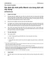
A1.1 Cell Assembly—Comprises a cylindrical sample
chamber bored in the center of an aluminum block with an
illuminated viewing window provided across its diameter. The
chamber is fitted with an airtight cover to the underside of
which is attached a transparent cylinder, thus forming an inner
and outer cell to the chamber. The cells are separated by a
stainless steel test filter which is attached to the lower end of
the inner cell cylinder. A combined fill and drain point is fitted
to the outer chamber (see Fig. A1.1).4
A1.2
−65°C.
A1.4 Pressure Sensor—A pressure sensor with a minimum
accuracy of 0.05 kPa is required to measure the pressure
differential across the test filter. This increases when wax
crystals form or when there is a change in state sufficient to
impede the flow through the test filter. The unit senses when the
pressure differential across the filter exceeds 1.33 kPa for more
than 1 6 0.05 s. When this occurs, the cooling cycle is stopped.
Pressure and vacuum are still applied as the specimen warms
and when the pressure differential has decreased to a point
below 1.33 kPa for 1 6 0.05 s, the electronic thermometer
display is held at the (flow) test result reading.
Cooling System—Temperature range from 5 to
A1.3 Specimen Pump—Comprises a cam-operated diaphragm pump driven by a synchronous motor. The pump
alternately applies pressure and vacuum to the inner cell, thus
A1.5
3
Mode Selection—To change the operation of the
D 4305 – 98a (2004)e1
FIG. A1.1 Schematic of Cell Assembly and Cooling System
apparatus so that completion of the test occurs at the plugging
(no-flow) point of the test filter.
platinum resistance temperature sensing probe shall be connected by means of screened leads to the thermometer.
A1.6 Drain Valve—Connected to the cell assembly allowing the sample to be drained at the conclusion of the test.
A1.9 Drying Chamber—A desiccant-filled drying chamber
is connected permanently to the outlet from the cell assembly
and ensures that the displaced air is kept moisture free.
A1.7 Syringe—Preset at 5 6 0.1 mL with a fitting that
matches the socket provided on the instrument. The syringe is
left in the socket for the duration of the test.
A1.10 Test Filters:
A1.10.1 26-µm, diameter 4.25 6 0.25 mm, stainless steel.
A1.10.2 42-µm, diameter 9 6 0.25 mm, stainless steel.
A1.8 Electronic Thermometer—Reading to 0.1°C, with a
minimum accuracy of 0.1°C, permanently fitted to the instrument and electronically linked to the programmed cycle. A
A1.11 Sample Filter—26-µm, stainless steel, fitted to the
socket, provided for injection of the sample with the syringe.
A2. PRECAUTIONARY STATEMENTS
A2.1 n-Heptane:
A2.1.1 Keep away from heat, sparks, and open flame.
A2.1.2 Keep container closed.
A2.1.3 Use with adequate ventilation. Avoid prolonged
breathing of vapor or spray mist.
A2.1.4 Avoid prolonged or repeated skin contact.
A2.2.1
A2.2.2
A2.2.3
A2.2.4
ignition.
A2.2.5
A2.2.6
A2.2 Aviation Turbine Fuel (Jet A or A-1, see Specification
D 1655):
4
Keep away from heat, sparks, and open flame.
Keep container closed.
Use with adequate ventilation.
Avoid buildup of vapors and eliminate all sources of
Avoid breathing vapor or spray mist.
Avoid prolonged or repeated contact with skin.
D 4305 – 98a (2004)e1
ASTM International takes no position respecting the validity of any patent rights asserted in connection with any item mentioned
in this standard. Users of this standard are expressly advised that determination of the validity of any such patent rights, and the risk
of infringement of such rights, are entirely their own responsibility.
This standard is subject to revision at any time by the responsible technical committee and must be reviewed every five years and
if not revised, either reapproved or withdrawn. Your comments are invited either for revision of this standard or for additional standards
and should be addressed to ASTM International Headquarters. Your comments will receive careful consideration at a meeting of the
responsible technical committee, which you may attend. If you feel that your comments have not received a fair hearing you should
make your views known to the ASTM Committee on Standards, at the address shown below.
This standard is copyrighted by ASTM International, 100 Barr Harbor Drive, PO Box C700, West Conshohocken, PA 19428-2959,
United States. Individual reprints (single or multiple copies) of this standard may be obtained by contacting ASTM at the above
address or at 610-832-9585 (phone), 610-832-9555 (fax), or (e-mail); or through the ASTM website
(www.astm.org).
5