Astm d 3427 15
Bạn đang xem bản rút gọn của tài liệu. Xem và tải ngay bản đầy đủ của tài liệu tại đây (194.18 KB, 6 trang )
Designation: D3427 − 15
Designation 313–01
Standard Test Method for
Air Release Properties of Hydrocarbon Based Oils1
This standard is issued under the fixed designation D3427; the number immediately following the designation indicates the year of
original adoption or, in the case of revision, the year of last revision. A number in parentheses indicates the year of last reapproval. A
superscript epsilon (´) indicates an editorial change since the last revision or reapproval.
1. Scope*
3. Terminology
1.1 This test method covers the ability of turbine, hydraulic,
and gear oils to separate entrained air.
3.1 Definitions of Terms Specific to This Standard:
3.1.1 air release time, n—the number of minutes needed for
air entrained in the oil to reduce in volume to 0.2 % under the
conditions of this test and at the specified temperature.
NOTE 1—This test method was developed for hydrocarbon based oils.
It may be used for some synthetic fluids; however, the precision statement
applies only to hydrocarbon based oils.
4. Summary of Test Method
1.2 The values stated in SI units are to be regarded as
standard. No other units of measurement are included in this
standard.
1.3 This standard does not purport to address all of the
safety concerns, if any, associated with its use. It is the
responsibility of the user of this standard to establish appropriate safety and health practices and determine the applicability of regulatory limitations prior to use.
4.1 Compressed air is blown through the test oil, which has
been heated to a temperature of 25 °C, 50 °C, or 75 °C. After
the air flow is stopped, the time required for the air entrained
in the oil to reduce in volume to 0.2 % is recorded as the air
release time.
NOTE 2—By agreement between the customer and the laboratory, the oil
may be heated at other temperatures. However, the precision at these
different temperatures is not known at present.
5. Significance and Use
2. Referenced Documents
2
5.1 Agitation of lubricating oil with air in equipment, such
as bearings, couplings, gears, pumps, and oil return lines, may
produce a dispersion of finely divided air bubbles in the oil. If
the residence time in the reservoir is too short to allow the air
bubbles to rise to the oil surface, a mixture of air and oil will
circulate through the lubricating oil system. This may result in
an inability to maintain oil pressure (particularly with centrifugal pumps), incomplete oil films in bearings and gears, and
poor hydraulic system performance or failure.
2.1 ASTM Standards:
D1193 Specification for Reagent Water
D1401 Test Method for Water Separability of Petroleum Oils
and Synthetic Fluids
D4057 Practice for Manual Sampling of Petroleum and
Petroleum Products
E1 Specification for ASTM Liquid-in-Glass Thermometers
2.2 DIN Standard:3
DIN 51 381
5.2 This test method measures the time for the entrained air
content to fall to the relatively low value of 0.2 % volume
under a standardized set of test conditions and hence permits
the comparison of the ability of oils to separate entrained air
under conditions where a separation time is available. The
significance of this test method has not been fully established.
However, entrained air can cause sponginess and lack of
sensitivity of the control of turbine and hydraulic systems. This
test may not be suitable for ranking oils in applications where
residence times are short and gas contents are high.
1
This test method is under the jurisdiction of ASTM Committee D02 on
Petroleum Products, Liquid Fuels, and Lubricants and is the direct responsibility of
Subcommittee D02.C0.02 on Corrosion and Water/Air Separability.
Current edition approved Oct. 1, 2015. Published November 2015. Originally
approved in 1975. Last previous edition approved in 2014 as D3427 – 14aɛ1. DOI:
10.1520/D3427-15.
This standard has been developed through the cooperative effort between ASTM
International and the Energy Institute, London. The EI and ASTM International
logos imply that the ASTM International and EI standards are technically
equivalent, but does not imply that both standards are editorially identical. Adopted
as a joint ASTM/IP standard in 2006.
2
For referenced ASTM standards, visit the ASTM website, www.astm.org, or
contact ASTM Customer Service at For Annual Book of ASTM
Standards volume information, refer to the standard’s Document Summary page on
the ASTM website.
3
Available from Beuth Verlag GmbH, Burggrafenstrasse 6, 1000 Berlin 30,
Germany.
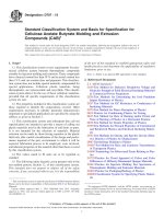
6. Apparatus
6.1 A schematic diagram of the apparatus is shown in Fig. 1.
The component parts are described as follows:
6.1.1 Test Vessel, made of borosilicate glass as shown in Fig.
2, consisting of a jacketed sample tube fitted with an air inlet
*A Summary of Changes section appears at the end of this standard
Copyright © ASTM International, 100 Barr Harbor Drive, PO Box C700, West Conshohocken, PA 19428-2959. United States
1
D3427 − 15
thermometer located as close as possible to the testing vessel
and meeting the specifications shown in 6.1.3.
NOTE 4—The application of thermal insulation to the pipework carrying
the heated compressed air is recommended.
6.1.5 Circulating Bath, approximately 10 L capacity with a
rate of flow of 10 L/min and capable of maintaining the test cell
at a temperature of 25 °C, 50 °C, or 75 °C within 60.1 °C.
NOTE 5—Use of water in the bath has been found to minimize
electrostatic effects.
NOTE 6—The application of thermal insulation to the pipework carrying
the heated bath fluid is recommended.
(Warning—The use of glass vessels with glass hose fittings
for circulating 75 °C bath medium is potentially dangerous.
Back pressure in excess of a gage pressure of 70 kPa can be
generated when the bath medium is pumped at the required
rate; this can cause fracture of the glass or slippage of the hose
connections. Use of a pressure relief valve set at 70 kPa is
recommended. In addition, use of a safety shield is recommended.)
6.2 Balance, capable of measuring density, accurate to
0.5 kg ⁄m3.
FIG. 1 Apparatus for the Determination of Air Release Time
6.3 Sinker, having a round or tapered bottom of 5 mL or
10 mL displacement, 80.0 mm 6 1.5 mm length. If the sinker
contains a thermometer, it shall be usable between 25 °C and
75 °C.
capillary, baffle plate, and air outlet tube. The two parts of each
test vessel should be marked and preferably used as a pair.
Interchanged parts may be used so long as the resultant test
vessel conforms to the stated dimensions.
6.4 Oven, capable of heating samples to 10 °C above the test
temperature.
NOTE 3—Users are advised to verify the distance between the air inlet
capillary and the bottom of the test cell as described in the method, by
using an appropriate measuring device. It has been noted by some
laboratories that variation from the required measurements has significant
effect on results.
6.5 Timer, readable to 1 s, with an accuracy of better than
0.1 %.
6.6 Pump, with a nonpulsating output and capable of
maintaining an air flow of 40 L/min at a pressure of 20 kPa
(optional, see 7.4).
6.1.2 Pressure Gage, covering the range from 0 kPa to
35 kPa, with divisions at least every 2 kPa, and an accuracy of
1.5 kPa.
6.1.3 Thermometers:
6.1.3.1 Air Thermometer, for measuring compressed air
temperature. ASTM Precision Thermometer having a range
from −20 °C to 102 °C, graduated in 0.2 °C and conforming to
the requirements for Thermometer 12C as prescribed in Specification E1 is suitable. A temperature sensor of at least
equivalent performance is also suitable. Care shall be taken to
avoid restricting the air path with the thermometer bulb or any
adapter used.
6.1.3.2 Sample Thermometer, for measuring the temperature
of the sample during preparation and trial runs. ASTM Precision Thermometer having a range from –20 °C to 102 °C,
graduated in 0.2 °C and conforming to the requirements for
Thermometer 12C as prescribed in Specification E1 is suitable.
A temperature sensor of at least equivalent performance is also
suitable.
6.1.4 Heater, to bring the compressed air up to measurement
temperature. A coil of copper tubing immersed in the circulating bath (see 6.1.5) is suitable at 25 °C, but additional heating
is necessary at 50 °C and 75 °C. This can be obtained by an
additional bath, or by using a separate steam or electric heat
exchanger. The temperature of the air shall be measured by a
7. Materials
7.1 Purity of Reagents—Reagent grade chemicals shall be
used in all tests. Unless otherwise indicated, it is intended that
all reagents conform to the specifications of the Committee on
Analytical Reagents of the American Chemical Society where
such specifications are available.4 Other grades may be used,
provided it is first ascertained that the reagent is of sufficiently
high purity to permit its use without lessening the accuracy of
the determination.
7.2 Purity of Water—Reagent water as defined by Type II of
Specification D1193.
7.3 Acetone, minimum reagent grade. (Warning—
Flammable. Health hazard.)
4
Reagent Chemicals, American Chemical Society Specifications, American
Chemical Society, Washington, DC. For Suggestions on the testing of reagents not
listed by the American Chemical Society, see Annual Standards for Laboratory
Chemicals, BDH Ltd., Poole, Dorset, U.K., and the United States Pharmacopeia
and National Formulary, U.S. Pharmacopeial Convention, Inc. (USPC), Rockville,
MD.
2
D3427 − 15
FIG. 2 Test Vessel
3
D3427 − 15
50 °C. Oils having a viscosity at 40 °C greater than 90 mm2/s
shall be tested at 75 °C.
7.4 Air, Compressed, dry and free from moisture,
particulates, and oil. Air from a cylinder or a nonpulsating
pump may be used. (Warning—Compressed gas under high
pressure.)
10.2 Warm approximately 200 mL of the oil to be tested in
an oven set at a temperature of 10 °C higher than the test
temperature. Allow the sample to reach the test temperature.
This may take about 20 min.
7.5 Cleaning Reagent, Cleaning either in hot Nochromix5
(Warning—Corrosive health hazard oxidizer), or a 24 h soak
at room temperature in Micro6 solution.
10.3 Pour 180 mL 6 5 mL of the heated sample into the test
vessel.
NOTE 7—Previously, chrome sulfuric acid was used in this procedure.
Other test methods (for example, Test Method D1401) have demonstrated
acceptable, statistically equivalent results when Nochromix or Micro is
used to replace sulfuric chromic acid for cleaning.
10.4 Allow the sample to equilibrate to the desired test
temperature, using the heating-up time previously established
(see 10.1) or by directly measuring the temperature.
7.6 n-Heptane, reagent grade. (Warning—Flammable.
Harmful if inhaled.)
10.5 Warm the sinker of the balance to the test temperature
in an air bath, such as a glass cylinder fitted with a suitable
cover situated in the circulating bath. When the sinker has
reached the test temperature, immerse it in the sample, taking
care that no air bubbles cling to it. Attach the sinker to the
beam of the density balance by means of the platinum wire so
that the bottom of the sinker is 10 mm 6 2 mm from the
bottom of the test vessel.
NOTE 8—Other alternate solvents, such as toluene, etc., may be used in
place of n-heptane.
8. Sampling
8.1 Sample in accordance with the instructions described in
Practice D4057.
9. Preparation of Apparatus
NOTE 10—The sinker can take approximately 20 min to reach 50 °C or
35 min to reach 75 °C.
9.1 Clean the interior of the test vessel, including the air
inlet and sinker, and all other glassware coming in contact with
the sample, before each determination in the following manner:
9.1.1 Rinse away the oil residue with n-heptane
(Warning—see 7.6) and acetone (Warning—see 7.3) and dry
by air blowing.
9.1.2 Clean the apparatus by immersing in cleaning reagent
in order to remove completely any traces of silicone.
9.1.3 Rinse with reagent water.
9.1.4 Rinse with acetone (Warning—see 7.3) and dry with
clean compressed air (Warning—see 7.4).
10.6 Allow the density reading to stabilize, read the density
from the balance to the nearest 0.1 kg/m3, and record it as the
initial density.
10.7 Return the sinker to the air bath and replace it with the
air inlet tube as shown in Fig. 2. After 5 min, start the supply
of air at a gage pressure of 20 kPa at the required temperature.
Maintain the pressure and temperature of the air 25 °C, 50 °C,
or 75 °C by readjustments, if necessary.
10.8 After 7 min 6 0.1 min, shut off the air and immediately
start the timer. Quickly remove the inlet tube from the test
vessel, and immerse the sinker in the oil/air dispersion. Attach
the wire to the beam and maintain a distance of 10 mm 6
2 mm between the bottom of the sinker and the bottom of the
test vessel.
NOTE 9—Oil misting occurs during blowing. The test vessel should be
in a hood, or the air outlet tube should be connected to a vent that removes
the vapors.
10. Procedure
10.1 Assemble the test apparatus as shown in Fig. 1. Set the
compressed air temperature to within 0.2 °C of the desired test
temperature. Set the circulating bath to give a specimen
temperature within 0.1 °C of the desired test temperature. The
required bath temperature setting and time for the specimen to
equilibrate can be established for an equipment setup by
making trial runs with a thermometer in the oil specimen. For
oils with a viscosity at 40 °C of less than 9.0 mm2/s, the test
temperature shall be 25 °C. For oils with a viscosity at 40 °C
between 9.0 mm2/s and 90 mm2/s, the test temperature shall be
NOTE 11—In the case of certain oils, which form a considerable volume
of oil/air dispersion, the top of the sinker can initially be in foam, and
hence, density readings at this time can be in error.
10.9 Record the time, to the nearest 0.1 min (6 s), for the
density to return to the target of 99.8 % of the initial density
(d0). If the time is greater than 30 min, discontinue the test.
NOTE 12—The test may be run for a longer period of time by agreement
between the laboratory and the customer.
NOTE 13—For some applications, the shape of the air release time curve
may be required. This can be implemented by recording the density at
intervals, as required.
10.10 Certain oils may lose light components during the air
saturation, thus changing their effective density. This will be
noted if the time for the density to return to the initial figure is
instantaneous. Where air release value information is required
for such oils, an air releasing time curve may be drawn. If the
loss causes any part of the sinker to be exposed, discontinue the
test and repeat, using a sample that is 10 mL larger than
previously used.
5
The sole source of supply of Nochromix known to the committee at this time
is Godax Laboratories, Inc., 720-B Erie Ave., Takoma Park, MD 20912. If you are
aware of alternative suppliers, please provide this information to ASTM International Headquarters. Your comments will receive careful consideration at a meeting
of the responsible technical committee,1 which you may attend.
6
The sole source of supply of Micro known to the committee at this time is
International Products Corp., P.O. Box 70, Burlington, NJ 08016. If you are aware
of alternative suppliers, please provide this information to ASTM International
Headquarters. Your comments will receive careful consideration at a meeting of the
responsible technical committee,1 which you may attend.
4
D3427 − 15
11. Calculation of Density
trichloroethane and chrome sulfuric acid in the cleaning procedure.
13.1.1 Repeatability—The difference between two test
results, obtained by the same operator with the same apparatus
under constant operating conditions on identical test material,
would in the long run, in the normal and correct operation of
the test method, exceed the following values only in one case
in twenty:
11.1 Density:
@ Mass of sinker in air ~ kg! 2 Mass of sinker in sample ~ kg! #
Volume of sinker ~ m 3 !
NOTE
(1)
Density of sample ~ kg/m 3 ! 5
14—A 10 mL sinker has a volume of 10 m3 × 10-6 m3.
11.2 Target Density:
Initial density ~ d 0 ! 3 0.998.
0.5 times the square root of their mean
(2)
13.1.2 Reproducibility—The difference between two single
and independent results obtained by different operators working in different laboratories on identical test material would, in
the long run, in the normal and correct operation of the test
method, exceed the following values only in one case in
twenty:
11.3 If the tare key of the balance is pressed while the sinker
is being weighed in air so that the reading is zeroed, then the
following may be used:
Mass of sinker in sample ~ kg!
(3)
Volume of sinker ~ m 3 !
15—Some instruments automatically make the above calcula-
Density of sample ~ kg/m 3 ! 5
NOTE
tions.
(4)
1.3 times the square root of their mean
(5)
13.2 The closely related test method DIN 51 381 reports
precision in another format. For ready comparison, the above
statement is shown in DIN terms in Table 1.
11.4 The volume of the sinker may be determined by
weighing it in air, then in water. The difference in mass (kg) ×
10–3 = volume in m3.
13.3 Bias—The procedure in Test Method D3427 for measuring air release properties of petroleum oils has no bias
because the value of the air bubble separation time is defined
only in terms of this test method. There is no known bias
relative to the DIN 51 381 method.
12. Reporting
12.1 Report the air release time, as recorded in 10.9, and the
test temperature in degrees Celcius.
13. Precision and Bias7
NOTE 18—The above precision was determined only at test temperatures of 50 °C and 82 °C. A new interlaboratory test program is planned.
NOTE 16—The program was run by six laboratories, using five samples
of unused steam turbine oils and base stocks with air used as the entrained
gas. Five samples were tested at one temperature and four at another.
Since some reports were incomplete, this resulted in 48 pairs of replicated
data.
14. Keywords
14.1 air entrainment; air release time; gear oil; hydraulic oil;
turbine oil
13.1 Precision—The precision of this test method as determined by statistical examination of interlaboratory results is as
follows:
TABLE 1 Comparison of ASTM and DIN Precision Data
Mean Test
Result,
min
Up to 5
Over 5 to 10
Over 10 to 15
NOTE 17—The precision statement was developed using 1.1.17
Supporting data (the results of the cooperative test program, from which these
values have been derived) have been filed at ASTM International Headquarters and
may be obtained by requesting Research Report RR:D02-1014.
Repeatability
Reproducibility
DIN
ASTM
DIN
ASTM
1
2
3
0.7
1.3
1.6
2
3
4
2.1
3.6
4.7
SUMMARY OF CHANGES
Subcommittee D02.C0 has identified the location of selected changes to this standard since the last issue
(D3427 – 14aɛ1) that may impact the use of this standard. (Approved Oct. 1, 2015.)
(1) Revised the title and scope, subsection 1.1 (Note 1).
(2) Revised subsection 6.1.1, adding new Note 3 and renumbering subsequent notes.
Subcommittee D02.C0 has identified the location of selected changes to this standard since the last issue
(D3427 – 14) that may impact the use of this standard. (Approved Dec. 1, 2014.)
(1) Revised 10.9 from 1 s to 0.1 min (6 s).
5
D3427 − 15
Subcommittee D02.C0 has identified the location of selected changes to this standard since the last issue
(D3427 – 12) that may impact the use of this standard. (Approved May 1, 2014.)
(4) Renumbered Sections 9 to 13.
(5) Updated section reference in 10.4 and 12.1.
(6) Revised 10.9 to record from 0.1 min to 1 s.
(1) Revised 6.1.5 to correct “host” to “hose fitting.”
(2) Revised 6.5 from 0.1 min to 1 s.
(3) Added new Section 8 on sample preparation.
ASTM International takes no position respecting the validity of any patent rights asserted in connection with any item mentioned
in this standard. Users of this standard are expressly advised that determination of the validity of any such patent rights, and the risk
of infringement of such rights, are entirely their own responsibility.
This standard is subject to revision at any time by the responsible technical committee and must be reviewed every five years and
if not revised, either reapproved or withdrawn. Your comments are invited either for revision of this standard or for additional standards
and should be addressed to ASTM International Headquarters. Your comments will receive careful consideration at a meeting of the
responsible technical committee, which you may attend. If you feel that your comments have not received a fair hearing you should
make your views known to the ASTM Committee on Standards, at the address shown below.
This standard is copyrighted by ASTM International, 100 Barr Harbor Drive, PO Box C700, West Conshohocken, PA 19428-2959,
United States. Individual reprints (single or multiple copies) of this standard may be obtained by contacting ASTM at the above
address or at 610-832-9585 (phone), 610-832-9555 (fax), or (e-mail); or through the ASTM website
(www.astm.org). Permission rights to photocopy the standard may also be secured from the Copyright Clearance Center, 222
Rosewood Drive, Danvers, MA 01923, Tel: (978) 646-2600; />
6