Astm d 991 89 (2014)
Bạn đang xem bản rút gọn của tài liệu. Xem và tải ngay bản đầy đủ của tài liệu tại đây (136.75 KB, 5 trang )
Designation: D991 − 89 (Reapproved 2014)
Standard Test Method for
Rubber Property—Volume Resistivity Of Electrically
Conductive and Antistatic Products1
This standard is issued under the fixed designation D991; the number immediately following the designation indicates the year of
original adoption or, in the case of revision, the year of last revision. A number in parentheses indicates the year of last reapproval. A
superscript epsilon (´) indicates an editorial change since the last revision or reapproval.
This standard has been approved for use by agencies of the U.S. Department of Defense.
3.1.1.1 Discussion—Generally, antistatic rubber products
are considered to have a resistance of 104 to 108 Ω.
3.1.2 rubber product, conductive—a rubber product having
an electrical conductivity of sufficient magnitude that might be
considered an electrical or thermal hazard.
3.1.2.1 Discussion—Generally, conductive rubber products
are considered to have a resistance of less than 104 Ω at 120 V.
3.1.3 volume resistivity—the ratio of the electric potential
gradient to the current density when the gradient is parallel to
the current in the material.
1. Scope
1.1 This test method covers the determination of volume
resistivity of rubbers used in electrically conductive and
antistatic products.
1.2 This test method assumes that the surface conductivity
is negligible compared with the conductivity through the
specimen.
1.3 The values stated in SI units are to be regarded as the
standard. The values given in parentheses are for information
only.
1.4 This standard does not purport to address all of the
safety concerns, if any, associated with its use. It is the
responsibility of the user of this standard to establish appropriate safety and health practices and determine the applicability of regulatory limitations prior to use.
4. Significance and Use
4.1 The electrical behavior of rubber products used in
particular applications is important for a variety of reasons
such as safety, static changes, current transmission, etc. This
test method is useful in predicting the behavior of such rubber
products.
2. Referenced Documents
5. Apparatus
2.1 ASTM Standards:2
D3182 Practice for Rubber—Materials, Equipment, and Procedures for Mixing Standard Compounds and Preparing
Standard Vulcanized Sheets
D4483 Practice for Evaluating Precision for Test Method
Standards in the Rubber and Carbon Black Manufacturing
Industries
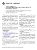
5.1 Electrode Assembly—The electrode assembly (Fig. 1)
shall consist of a rigid base made from an electrically insulating material having a resistivity greater than 10 TΩ·m (for
example, hard rubber, polyethylene, polystyrene, etc.) to which
a pair of current electrodes and a pair of potential electrodes are
fastened in such a manner that the four electrodes are parallel
and their top surfaces are in the same horizontal plane. Another
pair of current electrodes identical with the first pair shall be
fastened to a second piece of insulating material so that they
can be superimposed on the specimen directly above the first
pair. The current electrodes shall have a length at least 10 mm
(0.4 in.) greater than the specimen width, a width between 5
and 8 mm (0.2 and 0.3 in.), and a height uniform within 0.05
mm (0.002 in.) between 10 and 15 mm (0.4 and 0.6 in.). The
potential electrodes shall have a length and height equal to the
current electrodes and shall be tapered to an edge having a
radius of 0.5 mm (0.02 in.) maximum at the top surface. The
distance between the potential electrodes shall not be less than
10 mm (0.4 in.) nor more than 66 mm (2.6 in.) and shall be
known within 62 %. The current electrodes shall be equidistant outside the potential electrodes and separated from them
by at least 20 mm (0.8 in.). The electrodes shall be made from
3. Terminology
3.1 Definitions of Terms Specific to This Standard:
3.1.1 rubber product, antistatic—a rubber product sufficiently conductive to prevent a build-up of an electrical charge
on the surface and sufficiently insulating to prevent an electrical hazard.
1
This test method is under the jurisdiction of ASTM Committee D11 on Rubber
and is the direct responsibility of Subcommittee D11.10 on Physical Testing.
Current edition approved Nov. 1, 2014. Published December 2014. Originally
approved in 1948. Last previous edition approved in 2010 as D991 – 89 (2010).
DOI: 10.1520/D0991-89R14.
2
For referenced ASTM standards, visit the ASTM website, www.astm.org, or
contact ASTM Customer Service at For Annual Book of ASTM
Standards volume information, refer to the standard’s Document Summary page on
the ASTM website.
Copyright © ASTM International, 100 Barr Harbor Drive, PO Box C700, West Conshohocken, PA 19428-2959. United States
1
D991 − 89 (2014)
F — Distance between current and potential electrodes (20 mm minimum)
G — Distance between potential electrodes (see Note 2in Section 9)
depends on specimen size.
H — Width of current electrode, 5 to 8 mm (0.2 to 0.3 in.)
X — Insulation
A — Mass for applying contact force between current electrodes and
specimen
(300 N/m times specimen width in meters) (Note 1)
B — Mass for applying contact force between potential electrodes and specimen
(60 N/m times specimen width in meters) (Note 2)
C — Specimen
D — Current Electrodes
E — Potential Electrodes
NOTE 1—For a specimen 150 mm (6 in.) wide, mass is approximately 4.5 kg (10 lb).
NOTE 2—For a specimen 150 mm (6 in.) wide, mass is approximately 0.9 kg (2 lb).
FIG. 1 Electrode Assembly
and 60 N/m (0.9 kg (2 lb)) on the standard sheet, 150 mm (6
in.) wide, by the potential electrodes.
a corrosion-resistant metal such as brass, nickel, stainless steel,
etc. Insulation resistance between electrodes shall be greater
than 1 TΩ.
6. Specimens
5.2 Resistance-Measuring Device—Resistance may be measured by any electrical circuit that enables the current through
the current electrodes and the potential across the potential
electrodes to be measured within 2 %. Suitable devices for
measuring current are: (1) a precision milliammeter, or (2)
potential measurement across a reference resistor (resistance
value known within 2 % in series with the current electrodes.
Suitable devices for measuring potential are: (1) a galvanometer having a sensitivity of 1 µA or less per scale division in a
null-voltage circuit; (2) an electrostatic voltmeter having a d-c
resistance greater than 19 TΩ; or (3) an electrometer such as a
multirange voltmeter having an input d-c impedance greater
than 0.1 TΩ (Note 1). In any case, the current through the
potential electrodes during measurement must be less than 1 %
of that through the current electrodes. A stable source of d-c
potential shall be provided that can be adjusted to limit the
power dissipated in the specimen between potential electrodes
to approximately 0.1 W. Because of the large range of
resistances covered by conductive and antistatic rubbers, separate equipment for measuring resistances above and below
approximately 50 000 Ω is generally desirable.
6.1 Size—The width of the specimen shall be between 10
and 150 mm (0.4 and 6 in.) and the length shall be between 70
and 150 mm (2.8 and 6 in.). The width shall be uniform within
61 %. The thickness of cut specimens is specified in 6.3.
Molded specimens are specially prepared as described in 6.2
and therefore have a thickness of 2.0 6 0.2 mm (0.08 6 0.008
in.).
6.2 Molded Specimen—Standard sheets prepared in accordance with Practice D3182 may be used, provided the surface
of the uncured rubber is kept free of soapstone or other
contamination, and the surface of the vulcanized sheet is not
contaminated with mold lubricant. To avoid surface contamination and minimize distortion of specimen prior to test, sheets
may be molded between sheets of moisture-sensitive
cellophane, which can be readily removed after brief immersion in warm water. After removing the cellophane, the surface
of the sheet should be patted dry, taking care not to bend or
stretch the sheet.
6.3 Cut Specimen—The specimen shall be cut from a
product that has not been buffed or abraded. Surfaces of the
specimen shall be cleaned if necessary by rubbing with Fuller’s
earth and water, washing with distilled water, and drying in air.
The specimen shall be uniform in thickness within 65 %, not
more than 6.6 mm (0.26 in.), and if possible, not less than 2
mm (0.08 in.) thick. Care shall be taken to avoid distortion of
the specimen during preparation.
NOTE 1—Schematic diagrams of a typical apparatus that have been
found to be satisfactory are shown in Figs. X1.1 and X1.2.
5.3 Electrode Contacts—Masses shall be provided to produce a uniform contacting force across the width of the
specimen of approximately 300 N/m (4.5 kg (10 lb)) on the
standard sheet, 150 mm (6 in.) wide, by the current electrodes
2
D991 − 89 (2014)
TABLE 1 Type 1 Precision for Log(ρ)
7. Conditioning
7.1 The time between vulcanization and testing shall be not
less than 16 h nor more than 4 weeks for molded specimens.
Products shall be tested within 2 months after receipt by the
customer.
NOTE 1—Only two laboratories participated in the program for these
results.
Material
1
2
7.2 Specimens cut from products or molded specimens that
have been inadvertently distorted shall be annealed in air for 3
h at 23 6 2°C (73.4 6 3.6°F) to remove strains or other effects
of handling.
Mean
Level
3.392B
4.855
Sr = within laboratory standard deviation.
r = repeatability (in measurement units).
(r) = repeatability (in percent).
SR = between laboratory standard deviation.
R = reproducibility (in measurement units).
(R) = reproducibility (in percent).
B
Tabulated values (as used for analysis), log10(ρ).
NOTE 2—If l is made 64.5 mm (2.54 in.) and w and d are measured in
inches, the equation becomes:
8. Procedure
ρ 5 0.01 Vwd/I
8.1 After conditioning, place the specimen in the electrode
assembly, taking care to avoid flexing or distortion. The
identification portion of standard sheets shall be normal to the
calender grain and shall not be in contact with, nor lie between,
the current electrodes.
10. Report
10.1 Report the following information:
10.1.1 Temperature during conditioning and test,
10.1.2 Relative humidity during conditioning and testing,
10.1.3 Size of specimen,
10.1.4 Current through specimen in amperes,
10.1.5 Voltage across potential electrodes, and
10.1.6 Volume resistivity in ohm-metres, kilohm-metres, or
megohm-metres.
Current, mA
50
25
15
5
2
1
0.5
11. Precision and Bias3
11.1 These precision and bias statements have been prepared in accordance with Practice D4483. Refer to Practice
D4483 for terminology and other testing and statistical concepts.
8.3 As soon as the current has stabilized, in a maximum
time of 5 s, measure the potential difference across the
potential electrodes and the current through the current electrodes to the nearest 1 % of the respective values.
11.2 Because of the special nature of this test and its lack of
widespread use in the industry, a limited interlaboratory Type 1
test program was used to assess precision. Two materials
(rubber compositions) of different volume resistivity in the
form of cured sheets were prepared in one laboratory and sent
to the other participating laboratory. Both laboratories were
experienced in this testing.
8.4 Measure the thickness and width of the specimen.
8.5 Make the measurements on three specimens.
9. Calculation
11.3 In each laboratory the cured rubber sheets were measured for volume resistivity on two days, on each day by two
different operators. The within laboratory variation, therefore,
contains an “operator” and “day” component of variation.
9.1 Calculate the volume resistivity as follows for each
specimen:
ρ 5 Vwdk/Il
(2)
9.2 Report the median value for the three specimens as the
volume resistivity.
8.2 Adjust the current through the specimen after connection to the d-c source so that the power dissipation in the
specimen between potential electrodes is approximately 0.1 W.
The following values should not be exceeded for the maximum
current in the specimen for various potentials across the
potential electrodes:
Potential
3
6
10
30
75
150
300
Between LaboratoryA
SR
R
(R)
0.329
0.931
27.4
0.577
1.63
33.6
A
7.3 Specimens shall be conditioned for at least 16 h and
tested at a temperature of 23 6 2°C (73.4 6 3.6°F) and a
maximum relative humidity of 65 %. Molded specimens can be
conditioned in a desiccator. Specimens annealed at room
temperature may be stored in a closed container during the
conditioning period.
where:
ρ =
V =
I
=
w =
d =
l
=
k =
Within LaboratoryA
Sr
r
(r)
0.065
0.184
5.4
0.132
0.374
7.7
(1)
11.4 A test result is the median value of three measurements
of volume resistivity.
11.4.1 Table 1 gives the precision results. Due to the wide
range of volume resistivity values that are possible (10–1000
fold variation) the analysis was conducted using the (base 10)
logarithms of the (test result) volume resistivity, ρ.
volume resistivity, Ω·m,
potential difference, V, across potential electrodes,
current, A, through the current electrodes,
width of specimen,
thickness of specimen,
distance between potential electrodes,
factor depending on units in which, w, d, and l are
measured; that is, k is 0.001 if w, d, and l are in
millimetres and 0.0254 if they are in inches.
3
Supporting data have been filed at ASTM International Headquarters and may
be obtained by requesting Research Report RR:D11-1030.
3
D991 − 89 (2014)
11.4.2 The rather large between laboratory variation indicates the difficulty frequently experienced with this measurement by experienced laboratories and operators.
11.4.3 Bias—In test method statistical terminology, bias is
the difference between an average test value and the reference
or true test property value. Reference values do not exist for
this test method since the value or level of the test property is
exclusively defined by the test method. Bias, therefore, cannot
be determined.
APPENDIX
(Nonmandatory Information)
X1. CIRCUIT DIAGRAMS AND EXPLANATORY MATERIAL
close switch Sw7, set R7 for minimum resistance (least sensitive
position for galvanometer), and then close switch Sw5. For null
balance (zero reading on galvanometer), adjust R4, R5, and R6
and increase the sensitivity of the galvanometer by increasing
R7, eventually opening switch Sw7 to eliminate R7 altogether.
Close switch Sw6 to read voltage. It is desirable to limit the
wattage dissipated in the sample to 0.1 W between voltage
electrodes. This condition is satisfied by the product of volts
times milliamperes being not greater than 100.
X1.1 With switch Sw1 closed and the milliammeter set at
0–15 mA, turn the rotary switch Sw2 to develop current with
maximum values as follows:
Switch Contacts
Maximum Current, mA
1–4
5–6
7–9
15
3
1
Fine adjustment of current can be accomplished by resistances R1, R2, and R3.
X1.2 With switch Sw3 closed and rotary switch Sw4 swung
to approximate position, or one or two contacts less than Sw2,
A and A'—Current electrodes.
B and B'—Voltage electrodes.
Sw1, Sw3, Sw6, and Sw7—On-off toggle switches.
Sw2 and Sw4—Single-pole, 11-contact radio type rotary selector switches.
Sw5—Normally open momentary contact switch.
Source of Voltage—Two banks of dry cells each consisting of four 11⁄2-V cells,
and four 45-V “B” batteries—one connected at 221⁄2 V.
M—Milliammeter, Weston D-C. Model 430, ranged 0–0.15, 1.5, 15 mA scale
divisions 150; or equivalent milliammeter.
G—Galvanometer, having a sensitivity of 1 µA per scale division.
V—Voltmeter, Vacuum Tube Voltohmist, Electronic Designs Model 100, Electronic Designs, Inc., New York City; or equivalent performance vacuum
tube or solid state voltmeter. If desired, a multi-range d-c. voltmeter
with a sensitivity of 1000Ω/ V or better may be used. For protection
of this voltmeter, it is suggested that a two “gang” 11-contact rotary selector
switch be substituted for Sw 4 and the resistance multipliers for the voltmeter be
connected to the proper points on the second set of switch contacts. In this
case switch Sw6 could be eliminated.
R1, R2, R4, and R5—2-W, 0–10 000-Ω potentiometers, Mallory wire wound or
equivalent.
R3 and R6—2-W, 0–5000-Ω potentiometers, Mallory wire wound or equivalent.
R7—2-W, 0–3000-Ω potentiometer, Mallory wire wound or equivalent.
NOTE 1—Where it may be desirable to extend the range of this equipment, more batteries may be added. Caution must be exercised to prevent electrical
shock.
FIG. X1.1 Resistance-Measuring Device—Special Null Voltage Circuit
4
D991 − 89 (2014)
A and B — Current electrodes.
B and B — Voltage electrodes.
M — Milliammeter, Weston D-C. Model 430, ranged 0-0.15, 1.5,
15 mA scale divisions 150; or equivalent.
V — Voltmeter, multirange with input resistance of at least 100 M or
input current of less than 1. For example, Gould Alpha IV
Digital Multimeter, Keithly 616 Digital Electrometer, Penril
Corp. Data Tech. Model 30L; or equivalent.
P.S. — Variable, regulated, D.C. power supply to provide up to 200
VDC. For example, EICO 1030, Hope Electronics PS-200-IEM,
Kepco Inc. ABC 200M, Veepco Instruments Inc. (Lambda)
LP-415-FM; or equivalent. For samples requiring under
30 volts supply voltage, a lower voltage supply such as
EICO 1032 may be used.
FIG. X1.2 Alternative Circuitry
ASTM International takes no position respecting the validity of any patent rights asserted in connection with any item mentioned
in this standard. Users of this standard are expressly advised that determination of the validity of any such patent rights, and the risk
of infringement of such rights, are entirely their own responsibility.
This standard is subject to revision at any time by the responsible technical committee and must be reviewed every five years and
if not revised, either reapproved or withdrawn. Your comments are invited either for revision of this standard or for additional standards
and should be addressed to ASTM International Headquarters. Your comments will receive careful consideration at a meeting of the
responsible technical committee, which you may attend. If you feel that your comments have not received a fair hearing you should
make your views known to the ASTM Committee on Standards, at the address shown below.
This standard is copyrighted by ASTM International, 100 Barr Harbor Drive, PO Box C700, West Conshohocken, PA 19428-2959,
United States. Individual reprints (single or multiple copies) of this standard may be obtained by contacting ASTM at the above
address or at 610-832-9585 (phone), 610-832-9555 (fax), or (e-mail); or through the ASTM website
(www.astm.org). Permission rights to photocopy the standard may also be secured from the Copyright Clearance Center, 222
Rosewood Drive, Danvers, MA 01923, Tel: (978) 646-2600; />
5