Astm d 1072 06 (2012)
Bạn đang xem bản rút gọn của tài liệu. Xem và tải ngay bản đầy đủ của tài liệu tại đây (222.08 KB, 6 trang )
Designation: D1072 − 06 (Reapproved 2012)
Standard Test Method for
Total Sulfur in Fuel Gases by Combustion and Barium
Chloride Titration1
This standard is issued under the fixed designation D1072; the number immediately following the designation indicates the year of
original adoption or, in the case of revision, the year of last revision. A number in parentheses indicates the year of last reapproval. A
superscript epsilon (´) indicates an editorial change since the last revision or reapproval.
alternative procedures are cautioned that ammonia, amines,
substances producing water soluble cations, and fluorides will
interfere with the titration.
1. Scope
1.1 This test method is for the determination of total sulfur
in combustible fuel gases, when present in sulfur concentrations between approximately 25 and 700 mg/m3 (1 to 30 grains
per 100 cubic feet). It is applicable to natural gases, manufactured gases, mixed gases, and other miscellaneous gaseous
fuels.
5. Apparatus
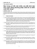
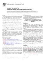
5.1 Burner (Fig. 1), as specified in the Appendix X1.
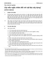
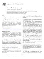
5.2 Chimneys, Absorbers and Spray Traps, (Fig. 2), as
specified in the Appendix X1.
1.2 The values stated in inch-pound units are to be regarded
as standard.
1.3 This standard does not purport to address all of the
safety concerns, if any, associated with its use. It is the
responsibility of the user of this standard to establish appropriate safety and health practices and determine the applicability of regulatory limitations prior to use.
5.3 Flow meter—A calibrated capillary flow meter for
predetermining and indicating the rate of flow of gas to the
burner. The capillary selected should be of such size that at the
required rate of flow the differential pressure is at least 20 cm
of water. A scale divided into millimeters will then provide a
reading precision of 6 0.5 %. Other metering devices, including but not limited to rotameters or dry displacement meters,
are suitable provided the reading precision is 6 0.5 % or better.
A flow controlling valve is attached to the inlet connection of
the flow meter.
2. Referenced Documents
2.1 ASTM Standards:2
D1193 Specification for Reagent Water
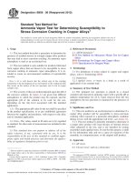
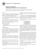
5.4 Vacuum System—A vacuum manifold equipped with a
vacuum regulating device, valves, and other necessary accouterments. An example vacuum system capable of performing
multiple test measurements is shown in Fig. 3. Other vacuum
system configurations can be used to perform this test method.
The vacuum system shall be connected to a vacuum pump
capable of providing a steady gas flow of 3 L of air per minute
through each absorber and capable of maintaining a constant
manifold pressure of approximately 40 cm of water below
atmospheric pressure.
3. Summary of Test Method
3.1 A metered sample of gas is burned in a closed system in
an atmosphere of sulfur-free air. The oxides of sulfur produced
are absorbed in sodium carbonate solution, where they are
oxidized to sulfate. The sulfate in the absorbent solution is
determined by titration with standardized barium chloride
solution, using tetra-hydroxy-quinone (THQ) as an indicator.
4. Interferences
4.1 There are no known interferences for the determination
of total sulfur in fuel gases when combustion is followed by
barium chloride titration. However, users employing barium
chloride titration following collection of sulfur dioxide by
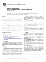
5.5 Air-Purifying System—A device supplying purified air
to the burner manifold at a constant pressure of approximately
200 mm of water and to the chimney manifold at a pressure of
1 to 2 cm of water. An example system configuration for
multiple tests is illustrated in Fig. 4; however, other airpurifying system configurations can be used to perform this test
method. The tubing that connects the chimneys to the manifold
shall be of an internal diameter not smaller than 0.63 cm in
order to prevent unnecessary restriction of airflow.
1
This test method is under the jurisdiction of ASTM Committee D03 on Gaseous
Fuels and is the direct responsibility of D03.05 on Determination of Special
Constituents of Gaseous Fuels.
Current edition approved Nov. 1, 2012. Published December 2012. Originally
approved in 1954. Last previous edition approved in 2006 as D1072 – 06. DOI:
10.1520/D1072-06R12.
2
For referenced ASTM standards, visit the ASTM website, www.astm.org, or
contact ASTM Customer Service at For Annual Book of ASTM
Standards volume information, refer to the standard’s Document Summary page on
the ASTM website.
5.6 Manometer—A water manometer for indicating the gas
pressure at the point of volume measurement. It is connected
between the flowmeter and the burner, with one leg open to the
atmosphere.
Copyright © ASTM International, 100 Barr Harbor Drive, PO Box C700, West Conshohocken, PA 19428-2959. United States
1
D1072 − 06 (2012)
6.10 Methyl Orange (CAS No 547-58-0) Indicator
Solution—Dissolve 0.1 g of methyl orange in 100 mL of water.
6.11 Silver Nitrate (CAS No 7761-88-8)Solution (17-g
AgNO3/L)—Dissolve 1.7 g of silver nitrate (AgNO3) in 100
mL of water. Store in a brown bottle.
6.12 Sodium Carbonate (CAS No 5968-11-6) Solution
(3.306-g Na2CO3/L)—Dissolve 3.306 g of sodium carbonate
(Na2CO3) in water and dilute to 1 L.
6.13 Sodium Hydroxide Solution (CAS No 1310-73-2)
(100-g NaOH/L)—Dissolve 100 g of technical grade sodium
hydroxide (NaOH) pellets in water and dilute to 1 L. Standardize against potassium hydrogen phthalate (See 6.1)
6.14 Sulfuric Acid(CAS No 7664-93-9) (1 + 16)—Mix 60
mL of concentrated sulfuric acid (H2SO4, sp gr 1.84) with 960
mL of water.
NOTE 1—All dimensions in millimetres.
FIG. 1 Gas Burner for Sulfur Determination
6.15 Tetrahydroxyquinone Indicator (THQ CAS No. 567648-2), in powdered form.
6. Reagents and Materials
6.16 Thorin indicator— (CAS No. 132-33-2)
6.1 Reagents Purity—Reagent grade chemicals shall be
used in all tests. Unless otherwise indicated, it is intended that
all reagents shall conform to the specifications of the Committee on Analytical Reagents of the American Chemical Society,
where such specifications are available.3 Other grades may be
used, provided it is first ascertained that the reagent is of
sufficiently high purity to permit its use without adversely
impacting the accuracy of the determination. Warning—
Sodium hydroxide is corrosive and can cause severe damage to
eyes and skin. Inhalation will irritate the nose, throat and lungs.
It reacts exothermically with water.
7. Calibration and Standardization
7.1 Sodium Hydroxide Solution Standardization— The following provides an example procedure for standardization;
other quantities of reagents, as convenient, can be used. Dry
and crushed potassium hydrogen phthalate (KHP) is heated in
an oven at 105 °C for 2 hours and allowed to cool to room
temperature in a desiccator. KHP (950 6 50 mg weighed to the
nearest 0.1 mg) is placed in an Erlenmeyer flask. Water (70
mL) and 2-4 drops of phenolphthalein are added. Titrate the
KHP solution with the sodium hydroxide solution prepared
under 6.13 to a faint pink color. Repeat the titration using a
second portion of KHP. Titrate a 70 mL water blank containing
1-4 drops of phenolphthalein to a faint pink color using the
sodium hydroxide solution prepared under 6.13. Repeat this
procedure and average the results. For both the water blank and
the KHP titration replicates should agree to 0.05 mL titrant. For
each KHP trial, independently calculate the normality for the
sodium hydroxide solution according to the following equation:
6.2 Purity of Water—Unless otherwise indicated, references
to water shall be understood to mean reagent water conforming
to Specification D1193.
6.3 Alcohol—Ethyl alcohol, denatured by Formula 30 or
3-A, or isopropyl alcohol.
6.4 Barium Chloride,(CAS No: 10361-37-2), Standard Solution (1 mL = 1 mg S)—Dissolve 7.634 g of barium chloride
(BaCl2·2H2O) in water and dilute to 1 L. The solution is
standardized gravimetrically by precipitation as barium sulfate
or by titration against sulfuric acid (see 6.12)
Normality of NaOH 5
mg KHP/204.23
(1)
~ mL NaOH 2 avg. mL blank!
Values for the two KHP trials should agree within 6 0.5
percent. If they do not, repeat the titrations or identify the
cause for the excessive discrepancy, or both.
7.2 Sulfuric Acid Standardization— The following provides
an example procedure for standardization; other quantities of
reagents, as convenient, can be used. Titrate the sulfuric acid
solution prepared under 6.14 against the sodium hydroxide
standardized in 7.1 using 2-4 drops of phenolphthalein as the
indicator. Repeat and average the result for the normality of the
sulfuric acid. Values for the two trials should agree within 6
0.5 percent. If they do not, repeat the titrations or identify the
cause for the excessive discrepancy, or both.
6.5 Hydrochloric Acid (CAS No 7647-01-0) (2.275-g HCl/
L)—Titrated against Na2CO3 solution (see 6.15), using methyl
orange indicator. Adjusted such that 1 mL of HCl solution is
equivalent to 1 mL of Na2 CO3 solution.
6.6 Hydrogen Peroxide (30 %) (H2O2;CAS No: 7722-84-1).
6.7 iso-Propanol (CAS No. 67630)
6.8 Potassium Hydrogen Phthalate (KHP; CAS No 87724-7) —Dry use.
6.9 Phenolphthalein (CAS No 77-09-8)
3
Reagent Chemicals, American Chemical Society Specifications, American
Chemical Society, Washington, DC. For suggestions on the testing of reagents not
listed by the American Chemical Society, see Analar Standards for Laboratory
Chemicals, BDH Ltd., Poole, Dorset, U.K., and the United States Pharmacopeia
and National Formulary, U.S. Pharmacopeial Convention, Inc. (USPC), Rockville,
MD.
7.3 Barium Chloride Solution Standardization— – Titrate
the barium chloride solution against the previously standardized sulfuric acid solution (see 7.2). This can be conveniently
accomplished by transferring 10.0 mL sulfuric acid to a flask
2
D1072 − 06 (2012)
NOTE 1—In the case of those dimensions for which no specific tolerances are designated above, the permissible variation is 610 % to the nearest 1
mm, provided, however, that in no case shall the deviation be greater than 5 mm.
FIG. 2 Detailed Drawing of Combustion and Absorption Apparatus for Sulfur Determination
added. This is titrated to a pink end point using the barium
chloride solution. Repeat the titration and average the results.
The replicate titrations should agree within 0.5 percent. If they
do not, repeat the titrations or identify the cause for the
excessive discrepancy, or both. Using this same procedure,
perform duplicate blank titrations using water in place of
sulfuric acid solution. The replicate titrations should agree
within 0.5 percent. Calculate the normality of the barium
chloride solution according to the following equation:
FIG. 3 Suction System for Sulfur Determination
Normality of Barium Chloride 5
where 40 mL iso-propanol and 2-4 drops thorin indicator are
3
10.0 mL x N Sulfuric Acid
~ avg. mL 2 avg. blank!
(2)
D1072 − 06 (2012)
to liberate approximately 250 to 500 Btu/h (Note 2). This rate
should be indicated by two index marks on the columns of the
flowmeter U-tube or timing a rate-index device. Make the
primary air connection from the purified air line to the upper
side arm of the burner by means of rubber or plastic tubing.
NOTE 2—Using this gas rate, the chimney and absorber should not
become overheated during a test. The appropriate volumetric rate of gas
flow will therefore depend on the heating value of the gas being tested.
8.5 Wash the spray trap, absorber, and chimney well with
water before each test. Charge the larger bulb of the absorber
with 10 mL of Na2CO3 solution (Note 3) and 20 mL of water.
Attach the spray trap and chimney, and connect them,
respectively, to the vacuum line and to the purified air line
using rubber or plastic tubing. Close the chimney opening
using a cork or other suitable plug.
NOTE 3—This quantity of Na2CO3 solution is adequate to absorb the
SO2 from the combustion products of 1 ft3 of gas containing 15 grains of
sulfur per 100 ft3 (0.03 m3 of gas containing 350 mg/m3 of sulfur.) For
higher concentrations of sulfur in the gas, the volume of Na2CO3 solution
should be proportionately increased, but the total initial liquid volume in
the absorber should not exceed 30 mL.
FIG. 4 Purified Air System for Sulfur Determination
7.4 An auto titration can be used to determine the concentration of both sodium hydroxide and sulfuric acid.
9. Procedure
9.1 Prior to each test, purge the flowmeter, burner, and
connection with the gas sample, and light the flame on the
burner. Adjust the gas-flow rate by its valve to conform with
the requirements prescribed in 8.4. Adjust the primary air flow
so that a soft blue flame is obtained, with no yellow tip.
8. Preparation of Apparatus
8.1 Place 300 to 400 mL of NaOH solution in the first
scrubber (Fig. 4) and the same amount of H2O2-H2SO4 solution
(300 mL of water, 30 mL of H2SO4 , and 30 mL of H2O2 (30 %
w/w)) in the second scrubber. Replace these solutions whenever the volume becomes less than two thirds of the original.
9.2 To start a determination, insert the burner into the
chimney, fastening it in place with rubber bands or springs.
Check, and readjust if necessary, gas flows to obtain a stable
flame. Note the time at which the burner was inserted, or note
the meter reading if an integrating meter is used.
8.2 When the apparatus is first assembled, adjust the valve
between the vacuum manifold and the spray trap so that
approximately 3 L of air per minute will be drawn through the
absorber when the chimney outlet is open to the atmosphere,
the absorber is charged with 30 6 2 mL of water, and the
pressure in the vacuum manifold is maintained at approximately 40 cm of water below atmospheric. When all adjustments have been made, remove the water from the absorbers.
9.3 Continue the test until approximately 0.03 m3 (1 ft3 ) of
gas is burned. Maintain the flowmeter differential at a constant
value during this period. Note the time, or the meter reading
when using an integrating meter, and remove the burner from
the chimney, replacing it with the cork or other suitable plug,
and continuing the suction on the absorber until the latter
attains room temperature. Extinguish the flame.
8.3 With the burner control valve closed, the valve to the
vacuum regulator fully open, and the pressure in the vacuum
manifold adjusted to approximately 40 cm of water below
atmospheric, turn on the purified air. Adjust the chimney
manifold control valve so that, at the required flow through the
absorber, only a small stream of air escapes at the pressurerelief valve, a small stream of air enters at the vacuum
regulator, and the pressure in the chimney manifold is 1 to 2 cm
of water. Minor adjustment of the vacuum regulator and
vacuum control valve may be necessary to achieve this
condition.
9.4 Unless an integrating-type meter is used for gas
measurements, disconnect the burner from the flowmeter.
Replace it with a connection to a calibrated wet-test meter that
has been purged with 5 ft3 (0.15 m3) of the gas being tested.
Adjust the flowmeter differential and the manometer reading to
that existing during the determination in 9.3 and time with a
stopwatch one complete revolution of the wet-test meter. A
needle value may be required at the inlet of the wet-test meter
to adjust the pressure and flow of gas so that both the flowmeter
and the manometer indicate the same values, respectively, that
existed during the determination.
9.4.1 Calculate the volume of gas in standard cubic feet
burned during the determination as follows:
NOTE 1—It is convenient to balance the air-flow system by regulating
the pressure in the vacuum manifold. This is done by raising or lowering
the air-inlet tube in the vacuum regulator by sliding it in a rubber sleeve.
8.4 When first assembling the apparatus, connect the gas
sample line using glass or aluminum tubing to the inlet of the
flowmeter. Connect the outlet of the flowmeter in a similar way
to the lower side arm of the burner. Adjust the valve for
controlling the rate of flow of gas so that gas is burned at a rate
V 5 ~ t d /10t c ! 3 @ 519.67/459.671T d # 3 @ P1 ~ m/13.6! 2 w # / ~ 30
2 0.522!
4
(3)
D1072 − 06 (2012)
10. Analysis of Absorbent
where:
V = volume of sample burned, in standard cubic feet at
60°F, 30 in. Hg, saturated;
td = time for determination, s;
tc = time of one revolution of wet test meter during
calibration, s;
Td = meter temperature, °F absolute;
P = barometric pressure, in. Hg;
m = manometer reading, in. water; and
w = vapor pressure of water at meter temperature, in. Hg.
10.1 When the absorber has cooled to room temperature,
wash the chimney and trap with the smallest possible quantity
of water, and add the washings to the solution in the absorber.
Add three drops of methyl orange indicator to the solution.
Titrate the excess Na2CO3 in the absorber with HCl to the
methyl orange end point, mixing the solution after each
addition of acid by alternate sucking and blowing on one end
of the absorber.
10.2 Discharge the tan color of the acid methyl orange with
a few drops of Na2CO3 solution and add 50 mL of ethyl or
isopropyl alcohol. Add about 0.5 g of tetra-hydroxy-quinone
indicator (THQ). After mixing the solution well, titrate with
BaCl2 solution. After 1 or 2 mL of the BaCl2 solution have
been added, add 1 mL of 0.1N AgNO3 solution, and continue
titration to the end point. The end point is reached when the
color of the solution changes from yellow to rose, which is
persistent with good mixing. Note and record the volume of
BaCl2 solution required to produce the red color.
NOTE 4—This calibration procedure avoids the necessity of calculating
corrections of the flowmeter calibration for each gas tested.
9.4.2 Calculate the volume in standard cubic metres as
follows:
~ 4 ! V 5 ~ t d /t c ! 3 @ 288.15/ ~ 2731151T d ! # 3 @ P1 ~ m/13.6! 2 w # / ~ 760
2 12.788!
(4)
where:
V = volume in cubic metres at standard conditions (15°C
and 101.325 kPa);
td = time of determination, s;
tc = time of calibration, s/m3;
Td = meter temperature, °C;
P = barometric pressure, mm Hg;
m = manometer reading, mm H2O; and
w = vapor pressure of H2O in mm Hg.
10.3 Using this same procedure as 10.2, perform a blank
titration using water in place of the sample solution.
NOTE 6—The AgNO3 intensifies the rose color at the end point.
11. Calculation
11.1 Calculate the concentration of sulfur from the results of
the BaCl2 titration, as follows (see Note 5):
NOTE 5—The calculated results in inch-pound and metric conditions are
not directly convertible. The calculation equations for inch-pound and
metric results are based on differing base conditions of temperature and
pressure (inch-pound – 60°F, 30 in. Hg or 14.73 psia; Metric—288.15 K
( + 15°C), 101.325 kPa). Any conversion must take these differences into
account.
S 5 @ ~ A 2 B ! /V # 3 1.543
where:
S =
A =
B =
V =
9.5 If a calibrated integrating dry displacement meter is
used for gas measurement, calculate the volume as follows:
V 5 V m @ 519.67/ ~ 459.671T d ! # 3 @ P1 ~ m/13.6! 2 w' # / ~ 30 2 0.522!
sulfur concentration in grains/100 standard ft3,
millilitres of BaCl2 solution used for sample titration,
millilitres of BaCl2 solution used for blank titration,
volume in ft3.
NOTE 7—One grain=64.799 milligrams; 1ft3= 0.0283 m3
(5)
S 5 @ ~ A 2 B ! /V # 3 3531
where:
Vm = meter reading at end of determination minus the meter
reading at the start of the determination, ft3 and
w' = actual partial pressure of water vapor in gas at drymeter temperature, and all other symbols are defined as
in 8.4.
where:
S =
A =
B =
V =
(8)
sulfur concentration in mg/m3,
millilitres of BaCl2 used for titration,
millilitres of BaCl2 used for blank titration,
volume in m3.
NOTE 8—The amount of BaCl2 solution used in the blank titration (B)
can be substituted with 0.2 mL as an approximate blank allowance for the
titration end point when the intended use of the data is not adversely
impacted.
V 5 V m 3 @ 288.15/ ~ 273.151T d ! # 3 @ P1 ~ m/13.6! 2 w' # / ~ 760
2 12.788!
(7)
(6)
where:
Vm = meter reading at end of determination minus the meter
reading at the start of the test and
w' = actual partial pressure of water vapor in gas at drymeter temperature.
12. Quality Assurance
12.1 Sulfuric Acid Control—A typical sulfuric acid control
procedure is as follows. Titrate 10.0 mL of 0.1N H2SO4 with
every set of samples, or every ten samples, whichever occurs
first. Results should be within 6 5 percent of the theoretical
value. If results are outside of the accepted range, restandardize the NaOH and recalculate the results. If the
recalculated results do not fall within range, investigate the
procedure until it is under control, and reanalyze the samples.
9.6 A duplicate test is suggested to assure the user that
representative results are obtained for a particular fuel sample.
Values for the two tests should agree within 6 0.5 percent. If
they do not, identify the cause for the excessive discrepancy,
mitigate the cause and re-perform the test(s).
5
D1072 − 06 (2012)
attainable in the BaCl2 titration, independent of the total
quantity of sulfate present in the absorber. The overall accuracy
should therefore be between 60.1 and 60.7 grains of sulfur
per 100 ft3, if metering accuracy of 62 % is attained, over the
concentration range to which the procedure is adaptable.
13.1.2 When 1 m3 of gas is burned, an absolute precision
equivalent to 60.06 mg/m3 should be attainable in the BaCl2
titration, independent of the total quantity of sulfate in the
absorber. The overall accuracy should therefore be between
60.06 and 60.42 mg/m3, if metering accuracy of 62 % is
attained, over the concentration range to which the procedure is
adaptable.
12.2 Sulfate Analysis Control—Analyze an EPA SO2 Quality Assurance vial or other suitable known standard with every
set of samples or every ten samples, whichever occurs first.
Results should be within 6 5 percent of theoretical. If results
do not fall within the accepted range, re-standardize the BaCl2
and recalculate the results. If the recalculated results fall
outside of the accepted range, investigate the procedure until it
is under control, and reanalyze the sample(s).
13. Precision and Bias
13.1 The accuracy of the results for a determination is
dependant on the accuracy with which the sample volume is
metered and the accuracy of the titration procedures.
13.1.1 When 1 ft3 of gas is burned, an absolute precision
equivalent to 60.1 grain of sulfur per 100 ft3 of gas should be
14. Keywords
14.1 gaseous fuels
APPENDIX
(Nonmandatory Information)
X1. APPARATUS
X1.1 Burner, of chemically resistant glass that conforms
with the dimensions shown in Fig. 1. It consists of a burner
tube to which the gas sample is admitted through a side arm
and orifice at the lower end. Surrounding the gas orifice tip is
a spherical enlargement of the burner tube into which purified
primary air for combustion is admitted. The burner tube is
provided with a standard-taper glass joint for connection with
the chimney. The upper end of the burner tube shall be
polished. When connected with the chimney, the burner shall
be held in position by rubber bands or metal springs stretched
between glass hooks on the burner and chimney.
X1.3 Absorber, of chemically resistant glass conforming to
the dimensions shown in Fig. 2, provided with standard-taper
glass joints for connection with the chimney and spray trap. A
fritted disk with average pore diameter from 150 to 200 µm
shall be sealed in the larger of the two bulbs of the absorber.
The fritted disk should be of such a permeability that, when 50
mL of water is placed in the absorber and air is passed through
at the rate of 3.0 L/min in the forward direction, the pressure
differential between the two sides of the absorber is between 15
and 23 cm of water and the air is dispersed uniformly.
X1.2 Chimney, of chemically resistant glass conforming to
the dimensions shown in Fig. 2, provided with standard-taper
glass joints for connection with the burner and absorber.
X1.4 Spray Trap, of chemically resistant glass conforming
to the dimensions shown in Fig. 2, provided with a standardtaper glass joint for connection with the absorber.
ASTM International takes no position respecting the validity of any patent rights asserted in connection with any item mentioned
in this standard. Users of this standard are expressly advised that determination of the validity of any such patent rights, and the risk
of infringement of such rights, are entirely their own responsibility.
This standard is subject to revision at any time by the responsible technical committee and must be reviewed every five years and
if not revised, either reapproved or withdrawn. Your comments are invited either for revision of this standard or for additional standards
and should be addressed to ASTM International Headquarters. Your comments will receive careful consideration at a meeting of the
responsible technical committee, which you may attend. If you feel that your comments have not received a fair hearing you should
make your views known to the ASTM Committee on Standards, at the address shown below.
This standard is copyrighted by ASTM International, 100 Barr Harbor Drive, PO Box C700, West Conshohocken, PA 19428-2959,
United States. Individual reprints (single or multiple copies) of this standard may be obtained by contacting ASTM at the above
address or at 610-832-9585 (phone), 610-832-9555 (fax), or (e-mail); or through the ASTM website
(www.astm.org). Permission rights to photocopy the standard may also be secured from the Copyright Clearance Center, 222
Rosewood Drive, Danvers, MA 01923, Tel: (978) 646-2600; />
6