Astm d 906 98 (2017)
Bạn đang xem bản rút gọn của tài liệu. Xem và tải ngay bản đầy đủ của tài liệu tại đây (110.78 KB, 4 trang )
This international standard was developed in accordance with internationally recognized principles on standardization established in the Decision on Principles for the
Development of International Standards, Guides and Recommendations issued by the World Trade Organization Technical Barriers to Trade (TBT) Committee.
Designation: D906 − 98 (Reapproved 2017)
Standard Test Method for
Strength Properties of Adhesives in Plywood Type
Construction in Shear by Tension Loading1
This standard is issued under the fixed designation D906; the number immediately following the designation indicates the year of
original adoption or, in the case of revision, the year of last revision. A number in parentheses indicates the year of last reapproval. A
superscript epsilon (´) indicates an editorial change since the last revision or reapproval.
This standard has been approved for use by agencies of the U.S. Department of Defense.
INTRODUCTION
The accuracy of the results of strength tests of adhesive bonds will depend on the conditions under
which the bonding process is carried out. Unless otherwise agreed upon between the manufacturer and
the purchaser, the bonding conditions shall be prescribed by the manufacturer of the adhesive. In order
to ensure that complete information is available to the individual conducting the tests, the
manufacturer of the adhesive shall furnish numerical values and other specific information for each of
the following variables:
(1) The moisture content of the wood at the time of bonding.
(2) Complete mixing directions for the adhesive.
(3) Conditions for application of the adhesive including the rate of spread or thickness of film,
number of coats to be applied, whether more than one coat is required.
(4) Assembly conditions before application of pressure, including the room temperature, length of
time, and whether open or closed assembly is to be used.
(5) Curing conditions, including the amount of pressure to be applied, the length of time under
pressure and the temperature of the assembly when under pressure. It should be stated whether this
temperature is that of the bond line, or of the atmosphere at which the assembly is to be maintained.
(6) Conditioning procedure before testing, unless a standard procedure is specified, including the
length of time, temperature, and relative humidity.
A range may be prescribed for any variable by the manufacturer of the adhesive if it can be assumed
by the test operator that any arbitrarily chosen value within such a range or any combination of such
values for several variables will be acceptable to both the manufacturer and the purchaser of the
adhesive.
This test method is intended to be applied only to adhesives
used in bonding wood to wood.
1. Scope
1.1 This test method covers the determination of the comparative shear strengths of adhesives in plywood-type
construction, when tested on a standard specimen and under
specified conditions of preparation, conditioning, and testing.
1.2 The values stated in SI units are to be regarded as the
standard. The values given in parentheses are provided for
information purposes only.
1.3 This standard does not purport to address all of the
safety concerns, if any, associated with its use. It is the
responsibility of the user of this standard to establish appropriate safety, health and environmental practices and determine the applicability of regulatory limitations prior to use.
1
This test method is under the jurisdiction of ASTM Committee D14 on
Adhesives and is the direct responsibility of Subcommittee D14.30 on Wood
Adhesives.
Current edition approved Aug. 1, 2017. Published August 2017. Originally
approved in 1947. Last previous edition approved in 2011 as D906 – 98 (2011).
DOI: 10.1520/D0906-98R17.
Copyright © ASTM International, 100 Barr Harbor Drive, PO Box C700, West Conshohocken, PA 19428-2959. United States
1
D906 − 98 (2017)
1.4 This international standard was developed in accordance with internationally recognized principles on standardization established in the Decision on Principles for the
Development of International Standards, Guides and Recommendations issued by the World Trade Organization Technical
Barriers to Trade (TBT) Committee.
2. Referenced Documents
2.1 ASTM Standards:2
D143 Test Methods for Small Clear Specimens of Timber
D907 Terminology of Adhesives
3. Terminology
3.1 Definitions:
3.1.1 Many terms in this test method are defined in Terminology D907.
3.1.2 plywood, n—a panel generally flat built up of layers of
veneer called plies, united under pressure by an adhesive to
create a panel with the bond between the plies as strong as, or
stronger than, the wood, and that has the following characteristics: (1) is constructed of an odd number of layers with grain
of adjacent layers perpendicular, (2) with a layer consisting of
either a single ply or two or more plies laminated with parallel
grain direction, and (3) with outer layers and all odd numbered
layers generally having the grain direction oriented parallel to
the long dimension of the panel.
3.1.2.1 Discussion—Generally, the grain of one or more
plies is approximately at right angles to the other plies, and
almost always an odd number of plies are used.
3.1.3 shear, n—in an adhesively bonded joint, stress, strain
or failure resulting from applied forces that tend to cause
adjacent planes of a body to slide parallel in opposite directions.
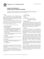
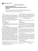
FIG. 1 Grips and Jaws
developed under the conditions prescribed in Section 8 is not
noticeably altered during testing.
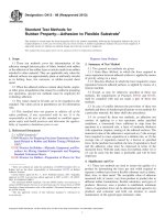
6. Test Specimens
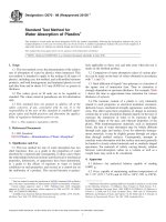
6.1 The test specimens shall conform to the form and
dimensions shown in Fig. 2. The specimens shall be cut from
test panels prepared as described in Sections 7 and 8.
6.2 At least 40 specimens, representing at least five different
panels, shall be prepared, selected and tested as prescribed in
Sections 9 and 10.
7. Preparation and Test Panels
7.1 The standard substrate for this test method is 1.6–mm
(1/16–in.) thick rotary-cut or sliced veneer of sweet birch
(Betula lenta) or yellow birch (Betula alleghaniensis). Any
other thickness or species of veneer may be substituted upon
written agreement between the party requesting this test and
the manufacturer of the adhesive. Select veneer that is free of
defects such as knots or distorted grain around knots, cracks,
short grain (fibers out of plane), rough surfaces, or unusual
discoloration that would indicate decay. Do not sand the
veneer.
4. Significance and Use
4.1 The way adhesives are used in plywood makes shear
strength an important performance criteria.
4.2 Shear strength measured by this test is suitable for use in
adhesive development, manufacturing quality control, and in
materials performance specifications.
5. Apparatus
7.2 Cut the selected veneer into a size suitable for pressing
and for cutting specimens with minimal waste. Allow at least
1⁄2-in. (13 mm) for trim around the edges.
5.1 The testing machine shall be adjusted to a loading rate
of between 4535 and 7560 g/s (600 and 1000 lb/min). Where
the testing machine is adjusted by rate of crosshead movement
rather than load application rate, an appropriate head movement rate shall be selected so as to yield an average load
application rate in the 4535 to 7560 g/s (600 to 1000 lb/min)
range. It shall be provided with suitable grips and jaws so that
the specimen can be gripped tightly and held in alignment as
the load is applied. The grips and jaws shown in Fig. 1 have
been found satisfactory. The testing machine shall be located in
an atmosphere such that the moisture content of the specimens
Metric Equivalents
2
in.
mm
For referenced ASTM standards, visit the ASTM website, www.astm.org, or
contact ASTM Customer Service at For Annual Book of ASTM
Standards volume information, refer to the standard’s Document Summary page on
the ASTM website.
⁄
3.2
18
1
25.4
31⁄4
82.6
FIG. 2 Form and Dimensions of Test Specimen
2
D906 − 98 (2017)
NOTE 1—When cutting the veneer to size, ensure that the fiber direction
is parallel and perpendicular to the edges. Appearances may be deceptive.
If there is any question, the fiber direction should be checked with an
scratch awl.
7.3 Condition the veneer to within 61 % of the moisture
content recommended by the adhesive manufacturer or the
party requesting this test. In the absence of any guideline,
condition the veneer to 10 to 12 % moisture content based on
the oven dry weight. Check moisture content of recommended
samples in accordance with Sections 124 to 127 of Test
Methods D143.
7.4 Prepare the adhesive in accordance with the adhesive
manufacturer’s instructions.
7.5 Apply the adhesive to each veneer in accordance with
the adhesive manufacturer’s instructions. Allow the prescribed
open assembly time, if any, before reassembling the veneer.
Reassemble the veneer with the fiber direction of the center
veneer perpendicular to the two face veneer. Allow the prescribed closed assembly time, if any, before pressing. Press the
assembly under the conditions prescribed by the adhesive
manufacturer.
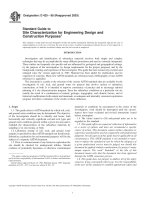
(a) Pulled Open
(b) Pulled Closed
FIG. 3 Lathe and Notch Orientations for Testing
parallel to the centerline of the jaws. If jaws such as those in
Fig. 1 are used, then the specimen should be perfectly aligned
with the pairs of jaws directly above each other and in such a
position that an imaginary straight vertical line would pass
through the center of the core ply and through the points of
suspension A and B as shown in Fig. 1. Test specimens from
each panel in numbered sequence and place in the jaws
alternately so that in one case the upper notch is to the left and
in the other case to the right. Apply the load at a rate of 4535
to 7560 g/s (600 to 1000 lb/min), or select a crosshead speed
that will yield this.
8. Conditioning of Test Panels
8.1 Upon removal from pressure, condition the panels at a
relative humidity of 50 6 2 % and at a temperature of 23 6
1°C (73.4 6 2°F) either for a period of 7 days, or until the
specimens reach equilibrium as indicated by no progressive
changes in weight, whichever is the longer period. The length
of this period of conditioning may be extended beyond this
limit by written agreement between the purchaser and the
manufacturer of the adhesive.
9. Preparation of Specimens
9.1 Cut the test specimens as shown in Fig. 2. This is best
accomplished by cutting the notches to the proper width, depth,
and location in the test panel, using a hollow-ground grooving
saw or any other method that will give equally satisfactory
results. Cut the notches in the panel in such a manner as to
ensure that when the specimens are subjected to loading, the
lathe checks in the center ply of half the specimens will be
pulled open (tension) (see Fig. 3(a)), while in the other half the
lathe checks will be pulled closed (compression) (see Fig.
3(b)). One method of accomplishing this is by notching the
panel as illustrated in Fig. 4. When the panel has been notched,
the individual specimens may be cut from the panel. Number
them consecutively from one end of the panel to the other and
identify with regard to panel of origin. Select the specimens to
be tested so that an even and equal number of specimens are
taken from each end of each panel. Measure the width of each
specimen and the distance between notches to the nearest 0.025
cm (0.01 in.) to determine the shear area.
11. Calculation
9.2 Retain the specimens in the conditioning atmosphere
described in Section 8, until tested, except during the cutting
operations.
12.1 The report shall include the following:
12.1.1 Complete identification of the adhesive tested including type, source, manufacturer’s code numbers, form, etc., and
the wood species used as well as its moisture content when
used,
12.1.2 Application and bonding conditions used in preparing the specimens,
11.1 Record the load at failure to the nearest 35 kPa (5 psi)
and the estimated wood failure to the nearest 5 %. Express all
failing loads in grams per square centimetre (or pounds per
square in.) of shear area, calculated to the nearest 0.06 cm2
(0.01 in2).
11.2 Calculate the average failing load for the group of
specimens cut from each end of each test panel. Combine the
groups having the higher average failing load from each of the
various test panels into one major group representing half of
the total number of test specimens. Combine the remaining half
of the test specimens, made up of the groups having the lower
average failing load from each of the various test panels into a
second major group. Calculate the average failing load and
average percentage wood failure for each of the two major
groups.
12. Report
10. Procedure
10.1 Place the test specimen in the jaws of the grips in the
testing machine so that the specimen is perfectly aligned and
3
D906 − 98 (2017)
Metric Equivalents
in.
mm
⁄
3.2
18
1
25.4
31⁄4
82.6
4
101.6
14
354.8
FIG. 4 Size of Test Panel and Method of Cutting and Numbering of Test Specimens
12.1.3 Conditioning procedure used for the specimens,
12.1.4 Temperature and relative humidity in the test room,
12.1.5 Number of specimens tested,
12.1.6 Number of panels represented,
12.1.7 Individual test results identified with regard to panel
of origin and specimen number, and
12.1.8 Average failing load and average percentage wood
failure for each of the two major groups of specimens.
13. Precision and Bias
13.1 A precision and bias statement does not exist for this
test method because resources necessary for round-robin testing have not been forthcoming.
14. Keywords
14.1 plywood; shear
ASTM International takes no position respecting the validity of any patent rights asserted in connection with any item mentioned
in this standard. Users of this standard are expressly advised that determination of the validity of any such patent rights, and the risk
of infringement of such rights, are entirely their own responsibility.
This standard is subject to revision at any time by the responsible technical committee and must be reviewed every five years and
if not revised, either reapproved or withdrawn. Your comments are invited either for revision of this standard or for additional standards
and should be addressed to ASTM International Headquarters. Your comments will receive careful consideration at a meeting of the
responsible technical committee, which you may attend. If you feel that your comments have not received a fair hearing you should
make your views known to the ASTM Committee on Standards, at the address shown below.
This standard is copyrighted by ASTM International, 100 Barr Harbor Drive, PO Box C700, West Conshohocken, PA 19428-2959,
United States. Individual reprints (single or multiple copies) of this standard may be obtained by contacting ASTM at the above
address or at 610-832-9585 (phone), 610-832-9555 (fax), or (e-mail); or through the ASTM website
(www.astm.org). Permission rights to photocopy the standard may also be secured from the Copyright Clearance Center, 222
Rosewood Drive, Danvers, MA 01923, Tel: (978) 646-2600; />
4