An analogue recurrent neural networks
Bạn đang xem bản rút gọn của tài liệu. Xem và tải ngay bản đầy đủ của tài liệu tại đây (1.11 MB, 7 trang )
Edith Cowan University
Research Online
ECU Publications
2005
An analogue recurrent neural networks for
trajectory learning and other industrial applications
Ganesh Kothapalli
Edith Cowan University
This conference paper was originally published as: Kothapalli, G. (2005). An analogue recurrent neural networks for trajectory learning and other
industrial applications. Proceedings of 3rd IEEE International Conference on Industrial Informatics, 2005. INDIN '05. 2005 (pp. 462 - 467 ). Perth.
IEEE. Original article available here
This Conference Proceeding is posted at Research Online.
/>2005
3rd
IEEE
International
Conference
on
Industrial
Informatics
(INDIN)
An
analogue
recurrent
neural
network
for
trajectory
learning
and
other
industrial
applications
Ganesh
Kothapalli
Edith
Cowan
University,
School
of
Engineering
and
Mathematics,
Joondalup,
WA
6027,
Australia.
e-mail:
g.kothapalligecu.edu.au
Abstract
A
real-time
analogue
recurrent
neural
network
(RNN)
can
extract
and
learn
the
unknown
dynamics
(and
features)
of
a
typical
control
system
such
as
a
robot
manipulator.
The
task
at
hand
is
a
tracking
problem
in
the
presence
of
disturbances.
With
reference
to
the
tasks
assigned
to
an
industrial
robot,
one
important
issue
is
to
determine
the
motion
of
the
joints
and
the
effector
of
the
robot.
In
order
to
model
robot
dynamics
we
use
a
neural
network
that
can
be
implemented
in
hardware.
The
synaptic
weights
are
modelled
as
variable
gain
cells
that
can
be
implemented
with
a
few
MOS
transistors.
The
network
output
signals
portray
the
periodicity
and
other
characteristics
of
the
input
signal
in
unsupervised
mode.
For
the
specific
purpose
of
demonstrating
the
trajectory
learning
capabilities,
a
periodic
signal
with
varying
characteristics
is
used.
The
developed
architecture,
however,
allows
for
more
general
learning
tasks
typical
in
applications
of
identification
and
control.
The
periodicity
of
the
input
signal
ensures
convergence
of
the
output
to
a
limit
cycle.
On-line
versions
of
the
synaptic
update
can
be
formulated
using
simple
CMOS
circuits.
Because
the
architecture
depends
on
the
network
generating
a
stable
limit
cycle,
and
consequently
a
periodic
solution
which
is
robust
over
an
interval
of
parameter
uncertainties,
we
currently
place
the
restriction
of
a
periodic
format
for
the
input
signals.
The
simulated
network
contains
interconnected
recurrent
neurons
with
continuous-time
dynamics.
The
system
emulates
random-direction
descent
of
the
error
as
a
multidimensional
extension
to
the
stochastic
approximation.
To
achieve
unsupervised
learning
in
recurrent
dynamical
systems
we
propose
a
synapse
circuit
which
has
a
very
simple
structure
and
is
suitable
for
implementation
in
VLSI.
Index
Terms-
Artificial
neural
network
(ANN),
Electronic
Synapse,
trajectory
tracking,
Recurrent
Neurons.
I.
INTRODUCTION
Recently,
interest
has
been
increasing
in
using
neural
networks
for
the
identification
of
dynamic
systems.
Feedforward
neural
networks
are
used
to
learn
static
input-
output
maps.
That
is,
given
an
input
set
that
is
mapped
into
a
corresponding
output
set
by
some
unknown
map,
the
feedforward
net
is
used
to
learn
this
map.
The
extensive
use
of
these
networks
is
mainly
due
to
their
powerful
approximation
capabilities.
Similarly,
recurrent
neural
networks
are
natural
candidates
for
leaming
dynamically
varying
input-output.
For
instance,
one
class
of
recurrent
neural
networks
which
is
widely
used
are
the
so-called
Hopfield
networks.
In
this
case,
the
parameters
of
the
network
have
a
particular
symmetric
structure
and
are
chosen
so
that
the
overall
dynamics
of
the
network
are
asymptotically
stable
[1].
If
the
parameters
do
not
have
a
symmetric
structure
the
analysis
of
the
network
dynamics
becomes
intractable.
Despite
the
complexity
of
the
internal
dynamics
of
recurrent
networks,
it
has
been
shown
empirically
that
certain
configurations
are
capable
of
learning
non-constant
time-varying
motions.
The
capability
of
RNNs
of
adapting
themselves
to
leam
certain
specified
periodic
motions
is
due
to
their
highly
nonlinear
dynamics.
So
far,
certain
types
of
cyclic
recurrent
neural
configurations
have
been
studied.
These
types
of
recurrent
neural
networks
are
well
known,
especially
in
the
neurobiology
area,
where
they
have
been
studied
for
about
twenty
years.
The
existence
of
oscillating
behaviour
in
certain
cellular
systems
has
also
been
documented
[1-3,10].
Such
cellular
systems
have
the
structure
of
what,
in
engineering
applications,
has
become
known
as
a
recurrent
neural
network.
Thus
the
neural
network
behaviour
depends
not
only
on
the
current
input
(as
in
feedforward
networks)
but
also
on
previous
operations
of
the
network
[4].
II.
ANN
FOR
TRAJECTORY
TRACKING
In
this
paper
we
treat
a
neural
network
configuration
related
to
control
systems.
We
describe
a
class
of
recurrent
neural
networks
which
are
able
to
learn
and
replicate
autonomously
a
particular
class
of
time
varying
periodic
signals.
Neural
networks
are
used
to
develop
a
model-based
control
strategy
for
robot
position
control.
In
this
paper
we
investigate
the
feasibility
of
applying
single-chip
electronic
(CMOS
IC)
solutions
to
track
robot
trajectories.
0-7803-9094-6/05/$20.00
@2005
IEEE
462
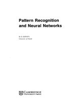
Fig.
1.
The
block
diagram
of
the
proposed
recurrent
neural
network.
Neural
network
with
dynamic
neurons
The
block
diagram
of
the
type
of
network
under
study
is
illustrated
in
the
Fig.
1.
In
this
figure
u(t)
is
the
input
and
v,(t)
is
the
output
of
the
network.
A
recurrent
network
of
the
type
depicted
in
the
Fig.
1
is
described
by
the
following
system
of
differential
equations
XI
=
RIV-
RIC,
dx
Ra
dt
R
va
RI
v'iz,
=_x
_RIv
Ra
= R,v
T
Ra
RI
=-_xI
+yi(x2)
Similarly,
Vr2X2
=-_x2
±yf/(XI)
+
U(t)
Finally,
for
the
output
of
the
circuit,
we
have,
=
-Vx
-
F-OWI
-y4IXI
21)IX
R
RR
=
-v
x
+
WIV(XI)
+
w)2
Y02)
The
time
constants
v,
z-l,
and
r2
govern
the
dynamics
of
the
network,
providing
first
order
low-pass
filtering
in
the
evolution
of
the
neuron
state
variables.
A
more
elaborate
model
of
neural
dynamics
would
incorporate
individual
Subcimudshow?
Ma,
R
2"
R'2
FOX
adjustable
time
constants
at
the
level
of
the
synaptic
contributions
[5-7].
An
alternative
type
of
RNN
that
can
be
described
by
the
differential
equations
given
below
can
also
be
built
with
the
electronic
neurons
discussed
in
the
next
section.
We
see
that
the
above
schematic
(Fig.
1)
implements
the
neural
network
with
only
two
dynamic
neurons
(neuron
circuit
is
shown
in
Fig.
2.).
The
equations
of
the
branch
currents
(Iml
and
Im2)
discussed
in
the
next
section
suggest
the
synapses
are
suitable
to
implement
both
types
of
RNN
represented
by
either
(1)
or
(2).
The
simulated
network
contained
six
fully
interconnected
recurrent
neurons
with
continuous-time
dynamics.
The
simulated
neural
network
can
be
described
by
a
general
set
of
equations
such
as
the
ones
given
below.
N
r5',
=y'Wi
-
exp(y,)
-A
Lexp(yj)
N
=y'+
W
-(1
-A)
exp(y,)
-2ALexp(yj)
(2)
with
x,(t)
the
neuron
state
variables
constituting
the
outputs
of
the
network,
x,(t)
the
external
inputs
to
the
network,
and
a(.)
a
sigmnoidal
activation
function.
The
value
for
-r
is
kept
fixed
and
uniform
in
the
present
implementation.
There
are
several
free
paramneters,
to
be
optimally
adjusted
by
the
learning
process.
For
example
if
we
implement
a
fully
in-
terconnected
RNN,
there
will
be
36
connection
strengths
Wij
and
-6
thresholds
Oj.
The
so
called
triggering
nonlinear
function
of
the
neurons
associated
with
this
network
is
taken
as
tanh(x,)
and
is
shown
in
the
Fig.
1
as
VI(xi).
However,
it
is
likely
that
a
larger
class
of
triggering
functions
with
the
same
properties
of
oddity,
boundedness,
continuity,
monotonicity
and
smoothness
could
be
considered.
Such
triggering
functions
include
arctan(x),
(1I+
e-x
)1,
e
x2
etc.
In
the
463
next
section
we
will
introduce
a
synaptic
circuit
that
implements
the
oiw
shown
in
Fig.
1.
III.
RECURRENT
NEURON
CHARACTERISTICS
In
the
synaptic
circuit,
the
current
of
M5,
which
we
de-
note
as
IM5
acts
as
an
excitatory
current
which
increases
the
membrane
potential
vc,
while
the
currents
of
Ml
and
M2,
which
we
denote
as
IMI
and
IM2,
respectively,
act
as
lateral-
and
self-inhibitory
currents
which
decrease
the
membrane
potential.
In
this
synaptic
circuit,
the
node
equations
at
the
node
v,
are
as
follows:
c"
=
IM5
/M1
IM2
where
IMa
stands
for
the
current
of
transistor
Ma
of
the
synaptic
circuit.
It
should
be
noticed
that
the
left
side
of
the
above
equation
represents
the
current
of
the
capacitor,
while
the
right
side
of
the
equation
is
given
by
the
linear
combination
of
saturation
currents
of
MOS
transistors
op-
erating
in
the
subthreshold
(weak
inversion)
region.
The
input
transistors
are
operated
in
weak
inversion
for
two
rea-
sons.
In
this
configuration,
(1)
they
deliver
maximal
trans-
conductance
for
a
given
current
and
(2)
low
vgs
and
Vds
voltages
are
needed
for
large
swing.
This
implies
that
the
network
can
easily
be
implemented
by
the
MOS
circuit
of
Figure-2
operating
in
the
subthreshold
region
[8].
A
transistor
can
be
biased
in
different
ways
by
choosing
the
dependent
variable
as
current
or
voltage.
For
voltage
biasing,
the
gate-source
voltage
of
the
device
is
the
same
and
current
is
the
dependent
variable.
For
current
biasing,
the
current
in
the
devices
is
the
same
but
the
voltage
is
the
dependent
variable.
Current-mode
circuits
should
be
bi-
ased
deep
in
saturation
for
best
accuracy.
In
the
case
of
voltage-mode
circuits,
best
accuracy
is
obtained
in
weak-
inversion.
In
the
subtrhreshold
region
of
operation,
'M2
is
ideally
given
by
JM2
=10
exp(v,
/VT
)
V
tanh(x1)
,
of
a
voltage,
VT=
kT/q
(k
is
the
Boltzmann's
constant,
T
the
temperature,
and
q
the
charge
of
an
electron),
q
measures
the
effectiveness
of
the
gate
potential,
v1,
is
an
extemal
input
voltage,
C
represents
a
capacitance,
IX,
is
a
MOS
transistor
parameter,
and
/
represents
a
gain
constant.
We
have
conformed
to
the
standard
notation
in
writing
the
CMOS
equations
above
to
represent
the
dynamics
of
the
circuit
[9].
The
current
mirror
consisting
of
M2
and
M3
implies
that
the
output
current
of
the
synaptic
circuit
IM3
is
equal
to
IM2.
The
current
IMS
which
depends
on
the
input
vrn
acts
as
an
excitatory
input
and
is
given
by
IM5
=
I0
exp(vrn
/I
17V).
The
voltage
v,
is
amplified
by
the
common
source
amplifier
consisting
of
transistor
M3
and
its
load
M4.
VDD
Fig.
2.
The
circuit
diagram
of
the
proposed
recurrent
neuron.
V
c
Figure
3.
Small-signal
equivalent
of
the
synaptic
circuit.
Similarly,
Im,
is
given
as
IM
I
=
10
exp(vx
/
77
VT)
in
terms
of
the
gate-source
voltage
vt
of
MI,
as
long
as
it
operates
in
the
saturation
region
(vtr
>
4
VT).
where
v,
represents
a
transformed
variable
possessing
the
dimension
Analysis
of
the
synapse
circuit
The
synaptic
circuit
can
be
realized
in
two
different
formats.
The
format
shown
in
Fig.2
implements
the
synapse
as
a
gain
controlled
voltage
amplifier.
An
altemate
format
of
the
synapse
(shown
in
Fig.
4)
is
based
on
a
transimpedance
gain
function.
The
main
difference
between
these
two
circuits
is
the
presence
of
an
additional
464
.,
in
feedback
transistor
placed
between
v,
and
output
v0
(Compare
Figs.
2
and
4.).
In
both
cases
the
gate
terminal
of
transistor
Ml
can
be
used
to
control
the
gain
of
the
synapse.
In
this
case
the
small-signal
equivalent
circuit
shown
in
Fig.
3
can
be
used
to
show
that
the
voltage
gain
is
given
by:
Va
(s)
9m5
VI(S)
gm2
+
gdl
+
SCc
In
this
case,
the
output
of
the
synapse,
co
*
yV(xI)
goes
through
the
output
stage
integrator
and
the
voltage
vx
is
used
to
control
the
gate
of
transistor
Ml
of
the
synapse.
Hence
the
synapse
behaves
like
a
variable
gain
amplifier
controlled
by
the
variable
conductance
gdl.
In
other
words,
w,
is
a
function
of
the
state
vx.
Ms.1
V
V
¢m
vv
Vin
Fig.
4.
The
circuit
diagram
of
the
proposed
synapse
that
im-
plements
a
transimpedance
gain
function
Z7(s).
IV.
A
NEURAL
NETWORK
BASED
CONTROLLER
FOR
ROBOT
POSITION
CONTROL.
We
train
a
neural
network
to
learn
and
mimic
movement
of
a
robot
manipulator.
A
block
diagram
of
such
a
setup
is
depicted
in
Fig.
5.
The
neural
network
leams
the
behaviour
of
the
robot
manipulator
over
certain
time
horizon.
The
neural
network
also
optimizes
the
control
action
such
that
the
error
between
the
output
of
the
robot
manipulator
and
the
reference
(desired)
trajectory
is
minimized.
Effector
Trajectory
Reference
trajectory
Fig.
5.
Block
diagram
of
a
neural
network
based
robot
control
system.
Neural
network
with
sigmoidal
neurons
In
the
proposed
recurrent
neural
network
(Fig.
1)
we
need
a
sigmoidal
yI(xi)
function.
This
sigmoidal
circuit
shoule
be
suitable
for
implementation
in
CMOS.
We
will
introduce
a
simple
circuit
that
can
implement
the
sigmoidal
function
Fig.
6.
Circuit
diagram
to
implement
the
VI(xi)
finction.
VDD
The
circuit
shown
in
Fig.
6
is
a
linearized
transconductor
whose
output
current
ion,
is
proportional
to
tanh(vj,).
In
this
circuit,
the
G.
is
derived
from
a
cross
coupled
pair
of
matched
transistors
(M7
and
M8)
operating
in
the
triode
region.
In
this
configuration,
the
Gm
is
controlled
with
gate
voltages
Vc1
and
Vc2-
The
possibility
of
building
the
entire
electronic
system
discussed
in
this
paper
using
CMOS
technology
is
currently
explored.
In
the
absence
of
such
a
hardware
system,
we
are
465
2
studying
the
performance
by
simulating
an
operational
amplifier
based
conceptual
circuit
model.
V.
SIMULATION
OF
THE
PROPOSED
SYSTEM
The
novel
concepts
formulated
in
this
paper
can
be
experimentally
verified
by
the
manufacture
of
a
prototype
electronic
system.
The
circuits
needed
for
such
implementation
are
presently
simulated
using
CAD
packages.
For
example
the
circuits
of
sigmoidal
transfer
function
(Fig.
6)
and
synaptic
networks
(Figs.
2
and
4.)
were
designed
using
0.18
micron
CMOS
technology.
These
simulations
confirmed
the
scalability
of
the
modularized
architecture
of
the
learning
algorithm.
We
are
verifying
the
robustness
of
the
architecture
under
technology
parameter
perturbations.
These
simulation
results
will
be
discussed
during
the
presentation
at
the
conference.
As
an
alternative
to the
experimental
verification,
we
have
simulated
the
system
of
differential
equations
that
represent
the
proposed
recurrent
neural
network.
The
task
set
for
this
verification
is
to
apply
a
variety
of
input
waveforms
to
the
simulator
and
observe
the
output
waveforms.
The
inputs
to
the
simulator
explored
comprise
a
variety
of
waveforms
such
as
triangular,
saw-tooth,
square
and
sinusoids.
All
these
input
waveform
characteristics
such
as
frequency,
amplitude
and
phase
were
varied
and
the
ability
of
the
neurons
to
settle
to
a
limit
cycle
were
observed.
VI.
INDUSTRIAL
APPLICATIONS
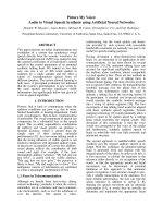
The
architecture
of
an
analog
recurrent
network
that
can
learn
a
continuous-time
trajectory
is
presented.
The
presentation
shows
that
the
RNN
does
not
distinguish
parameters
based
on
a
presumed
model
of
the
signal
or
system
for
identification.
Simulation
of
such
an
autonomous
tracking
of
a
trajectory
is
shown
in
Fig.
7.
The
vertical
(y-axis)
shows
the
robot
joint
position
in
radians
and
the
horizontal
(x-axis)
shows
time
in
msec.
In
many
decision
making
processes
such
as
manufacturing,
aircraft
control,
robotics
etc,
we
come
across
problems
of
control
systems
that
are
highly
complex,
noisy,
and
unstable.
A
tracking
system
or
agent
must
be
built
that
observes
the
state
of
the
environment
and
outputs
a
signal
that
affects
the
overall
system
in
some
desirable
way.
The
RNN
presented
here
is
suitable
for
such
tasks
because
it
is
general
and
robust
enough
to
respond
effectively
to
conditions
not
explicitly
considered
or
completely
modelled
by
the
designer.
The
architecture
of
the
analog
RNN
discussed
here
is
easier
to
implement
in
CMOS
VLSI
technology.
The
RNN
presented
is
a
very
small
network
consisting
only
of
two
synaptic weights.
However,
it
was
able
to
learn
periodicity
from
the
applied
signals
in
unsupervised
mode.
It
should
be
noted
that
this
network
is
scalable.
A
large
RNN
of
this
structure
can
be
built
with
relatively
little
hardware
and
can
be
used
for
a
variety
of
applications
in
control,
instrumentation
and
signal
processing
applications.
Fig.
7.
The
reference
trajectory
(red)
compared
with
tracking
RNN
output.
Fig.
8.
Output
of
the
RNN
for
an
applied
varying
input.
VII.
CONCLUSIONS
The
complexity
of
real
world
systems
often
defy
mathematical
analysis,
and,
most
interesting
tasks
in
these
environments
are
too
hard
for
designing
a
controller
strategy
by
hand.
Both
of
these
problems
can
be
avoided
by
learning
from
direct
interaction
given
two
essential
components:
a
simulator
that
behaves
like
the
environment,
and
a
learning
mechanism
that
is
powerful
enough
to
solve
the
task.
466
1
0.8
0.6
0.4
0.2-
I
In
this
paper
we
discussed
the
application
of;
analogue
recurrent
neural
network
to
learn
and
track
ti
dynamics
of
an
industrial
robot.
The
observations
ma(
from
this
study
suggest
that
RNNs
(similar
to
those
in
Fi
1)
can
be
applied
to
the
control
of
real
systems
th
manifest
complex
properties
-
specifically,
hig
dimensionality,
non-linearity
and
requiring
continuoi
action.
Examples
of
these
real
systems
include
aircri
control,
satellite
stabilization,
and
robot
manipulat
control.
We
conclude
that
robust
controllers
of
partial
observable
(non-Markov)
systems
require
real-tin
electronic
systems
that
can
be
designed
as
single-ch
Integrated
Circuits
(CMOS
IC).
This
paper
explored
su
techniques
and
identified
suitable
circuits.
an
he
de
g.
I
at
VIII.
REFERENCES
[1]
S.
Townley,
et
al.,
"Existence
and
Learning
of
centerline
Oscillations
in
Recurrent
Neural
Networks",
IEEE
Trans.
Neural
Networks
11:
luS
205-214,2000.
ift
[21
E.
Dijk,
"Analysis
of
Recurrent
Neural
Networks
with
application
to
:Or
speaker
independent
phoneme
recognition",
M.Sc
Thesis,
University
or
of
Twente,
June
1999.
[3]
G.
Cauwenberghs,
"An
Analog
VLSI
Recurrent
Neural
Network
lly
Leaming
a
Continuous-Time
Trajectory",
IEEE
Trans.
Neural
ne
Networks
7:
346-361,Mar.
1996.
lip
[4]
M.
Mori
et
al.,
Cooperative
and
Competitive
Network
Suitable
for
ch
Circuit
Realization",
IEICE
Trans.
Fundamentals,
vol.
E85-A,
No.9,
2127-2134,
Sept.
2002.
[5]
H.J.
Mattausch,
et
al.,
"Compact
associative-memory
architecture
with
fully
parallel
search
capability
for
the
minimum
Hamming
distance",
IEEE
J.
Solid-State
Circuits,
vol.37,
pp.218-227,
Feb.
2002.
[6]
G.
Indiveri,
"A
neuromorphic
VLSI
device
for
implementing
2-D
selective
attention
systems",
IEEE
Trans.
Neural
Networks,
vol.
12,
pp.1455-1463,
Nov.
2001.
[7]
C.K.
Kwon
and
K.
Lee,
"Highly
parallel
and
energy-efficient
exhaustive
minimum
distance
search
engine
using
hybrid
digital/analog
circuit
techniques",
IEEE
Trans.
VLSI
syst.
vol.
9,
pp.
726-729,
Oct.
2001.
[8]
T.
Asai,
M.
Ohtani,
and
H.
Yonezu,
"Analog
Integrated
Circuits
for
the
Lotka-Volterra
Competitive
Neural
Networks",
IEEE
Trans.
Neural
Networks,
vol.
10,
pp.
1222-1231,
Sep.
1999.
[9]
Donckers,
et
al.
"Design
of
complementary
low-power
CMOS
architectures
for
loser-take-all
and
winner-take-all"
Proc
of
7"
Int
conf.
on
microelectronics
for
neural,
fuzzy
and
bio-inspired
systems,
Spain,
Apr
1999.
[10]
A.
Ruiz,
D.
H.
Owens
and
S.
Townley,
"Existence,
learning
and
replication
of
limit
cycles
in
recurrent
neural
networks",
IEEE
Transactions
on
Neural
Networks,
vol.
9,
pp.
651-661,
Sept.
1998.
467