Astm c 110 16e1
Bạn đang xem bản rút gọn của tài liệu. Xem và tải ngay bản đầy đủ của tài liệu tại đây (830.99 KB, 25 trang )
This international standard was developed in accordance with internationally recognized principles on standardization established in the Decision on Principles for the
Development of International Standards, Guides and Recommendations issued by the World Trade Organization Technical Barriers to Trade (TBT) Committee.
Designation: C110 − 16´1
Standard Test Methods for
Physical Testing of Quicklime, Hydrated Lime, and
Limestone1
This standard is issued under the fixed designation C110; the number immediately following the designation indicates the year of
original adoption or, in the case of revision, the year of last revision. A number in parentheses indicates the year of last reapproval. A
superscript epsilon (´) indicates an editorial change since the last revision or reapproval.
This standard has been approved for use by agencies of the U.S. Department of Defense.
ε1 NOTE—Added research report footnote to Section 24 editorially in January 2017.
1. Scope
1.3 The values stated in SI units are to be regarded as
standard. The values given in brackets are mathematical
conversions to inch-pound units that are provided for information only and are not considered standard.
1.4 This standard does not purport to address all of the
safety concerns, if any, associated with its use. It is the
responsibility of the user of this standard to establish appropriate safety and health practices and determine the applicability of regulatory limitations prior to use.
1.1 These test methods cover physical testing of quicklime
and hydrated lime, and of limestone not otherwise covered in
ASTM standards.2
NOTE 1—Quicklime and hydrated lime have a high affinity for moisture
and carbon dioxide. Caution should be taken to protect both hydrated and
quicklime during sampling, storage, and testing (see Practice C50).
1.2 The test procedures appear in the following order:
Plastic Property Testing
Standard Consistency of Lime Putty
Plasticity of Lime Putty
Water Retention of Hydrated Lime
Air Entrainment
Soundness Testing
Autoclave Expansion of Hydrated and Hydraulic Lime
Popping and Pitting of Hydrated Lime
Application Testing
Slaking Rate of Quicklime
Dry Brightness of Pulverized Limestone
Limestone Grindability Determination by the Laboratory Ball Mill
Method
Settling Rate of Hydrated Lime
Particle Size Analysis
Residue and Sieve Analysis
Sieve Analysis of Dry Limestone, Quicklime, and Hydrated Lime
Fineness of Pulverized Quicklime and Hydrated Lime by Air
Permeabiity
Particle Size of Pulverized Limestone
Dry Screening of Hydrated Lime, Pulverized Quicklime, and
Limestone by Air Jet Sieving
Wet Sieve Analysis of Agricultural Liming Materials
Density Measurement
Apparent Loose Density of Hydrated Lime, Pulverized Quicklime,
and Limestone
Apparent Packed Density of Hydrated Lime, Pulverized
Quicklime, and Limestone
Relative Density (Specific Gravity) of Hydrated Lime Products
Section
5
6
7
8
2. Referenced Documents
2.1 ASTM Standards:3
C28/C28M Specification for Gypsum Plasters
C50 Practice for Sampling, Sample Preparation, Packaging,
and Marking of Lime and Limestone Products
C51 Terminology Relating to Lime and Limestone (as used
by the Industry)
C91 Specification for Masonry Cement
C109/C109M Test Method for Compressive Strength of
Hydraulic Cement Mortars (Using 2-in. or [50-mm] Cube
Specimens)
C136 Test Method for Sieve Analysis of Fine and Coarse
Aggregates
C150 Specification for Portland Cement
C185 Test Method for Air Content of Hydraulic Cement
Mortar
C188 Test Method for Density of Hydraulic Cement
C192/C192M Practice for Making and Curing Concrete Test
Specimens in the Laboratory
C204 Test Methods for Fineness of Hydraulic Cement by
Air-Permeability Apparatus
C207 Specification for Hydrated Lime for Masonry Purposes
C230/C230M Specification for Flow Table for Use in Tests
9
10
11
12
13
14
15
16
17
18
19
20
21
22
23
1
These test methods are under the jurisdiction of ASTM Committee C07 on
Lime and Limestone and are the direct responsibility of Subcommittee C07.06 on
Physical Tests.
Current edition approved Dec. 1, 2016. Published January 2017. Originally
approved in 1934. Last previous edition approved in 2016 as C110 – 16. DOI:
10.1520/C0110-16E01.
2
For tests on limestone as aggregate, see Vol 04.02 of the Annual Book of ASTM
Standards. For tests on limestone as building stone, see Vol 04.05 of the Annual
Book of ASTM Standards.
3
For referenced ASTM standards, visit the ASTM website, www.astm.org, or
contact ASTM Customer Service at For Annual Book of ASTM
Standards volume information, refer to the standard’s Document Summary page on
the ASTM website.
Copyright © ASTM International, 100 Barr Harbor Drive, PO Box C700, West Conshohocken, PA 19428-2959. United States
1
C110 − 16´1
PLASTIC PROPERTY TESTING
of Hydraulic Cement
C231 Test Method for Air Content of Freshly Mixed Concrete by the Pressure Method
C305 Practice for Mechanical Mixing of Hydraulic Cement
Pastes and Mortars of Plastic Consistency
C430 Test Method for Fineness of Hydraulic Cement by the
45-µm (No. 325) Sieve
C472 Test Methods for Physical Testing of Gypsum, Gypsum Plasters and Gypsum Concrete
C595 Specification for Blended Hydraulic Cements
C670 Practice for Preparing Precision and Bias Statements
for Test Methods for Construction Materials
C702 Practice for Reducing Samples of Aggregate to Testing
Size
C778 Specification for Standard Sand
C1005 Specification for Reference Masses and Devices for
Determining Mass and Volume for Use in the Physical
Testing of Hydraulic Cements
C1107 Specification for Packaged Dry, Hydraulic-Cement
Grout (Nonshrink)
D75 Practice for Sampling Aggregates
E11 Specification for Woven Wire Test Sieve Cloth and Test
Sieves
E29 Practice for Using Significant Digits in Test Data to
Determine Conformance with Specifications
E177 Practice for Use of the Terms Precision and Bias in
ASTM Test Methods
E691 Practice for Conducting an Interlaboratory Study to
Determine the Precision of a Test Method
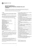
5. Standard Consistency of Lime Putty
5.1 Significance and Use:
5.1.1 In order to measure certain physical properties of a
lime putty, such as plasticity, it is necessary to have a uniform
or standard consistency (viscosity), since the property measurement is affected by the consistency level.
5.2 Apparatus:
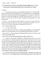
5.2.1 Modified Vicat Apparatus—The apparatus, constructed as shown in Fig. 1, shall consist of a bracket, A,
bearing a movable brass rod, B, 6.3 mm in diameter and of
suitable length to fit the Vicat bracket. A plunger, C, 12.5 mm
in diameter, made of aluminum tubing, shall be attached to the
lower end of the rod. The total weight of the rod with plunger
shall be 30 g. The lower end of the plunger shall be closed
without shoulders or curvature and the tube may be loaded with
shot to the specified weight. The total weight required may also
be obtained by means of a weight, D, screwed into the rod. The
rod can be held in any position by means of a screw, E, and has
a mark midway between the ends which moves under a scale,
F, graduated in millimetres, attached to the bracket, A.
5.2.2 Mold—The conical ring mold shall be made of a
noncorroding, nonabsorbent material, and shall have an inside
diameter of 70 mm at the base and 60 mm at the top, and a
height of 40 mm.
5.2.3 Base Plate—The base plate for supporting the ring
mold shall be of plate glass and about 100 mm square.
5.2.4 Mechanical Mixers.
5.3 Standard Consistency Determination:
3. Terminology
3.1 Definitions—Unless otherwise specified, for definitions
of terms used in these test methods see Terminology C51.
4. General Procedures
4.1 Sampling—Samples of lime and limestone for physical
analysis shall be taken and prepared in accordance with the
requirements of Practice C50 applicable to the material to be
tested.
4.2 Calculation:
4.2.1 The calculations included in the individual procedures
sometimes assume that the exact weight specified has been
used. Accurately weighed samples which are approximately
but not exactly equal to the weight specified may be used
provided appropriate corrections are made in the calculation.
Unless otherwise stated, weights of all samples and residues
should be recorded to the nearest 0.0001 g.
4.2.2 In all mathematical operations on a set of observed
values, the equivalent of two more places of figures than in the
single observed values shall be retained. For example, if
observed values are read or determined to the nearest 0.1 mg,
carry numbers to the nearest 0.001 mg in calculation.
4.3 Rounding Figures—Rounding of figures to the nearest
significant place required in the report should be done after the
calculations are completed, in order to keep the final results
free from calculation errors. The rounding procedure should
follow the principle outlined in Practice E29.
FIG. 1 Modified Vicat Apparatus
2
C110 − 16´1
5.3.1 Mechanical Mixing Procedure Using the Vac-UMixer—To a measured amount of water contained in an 800
cm3 Vac-U-Mix bowl, add 300 g of hydrated lime and hand
mix for 10 s with a stiff spatula (Note 2). Cover putty to
prevent evaporation of water. After the applicable soaking
period, 30 min maximum for Type S, special hydrated lime,
and not less than 16 h nor more than 24 h for Type N, normal
hydrated lime, insert the paddle assembly and mix the putty for
30 s with the mechanical mixer. Remove the paddle assembly
and scrape down any putty adhering to it and to the sides of the
mixing bowl. Remix for 30 s and determine the consistency as
prescribed in 5.3. If the penetration is less than 15 mm, return
all of the material to the mixer bowl, add additional water, and
remix for 15 s. If the penetration is greater than 25 mm, repeat
the test.
NOTE 2—Most lime hydrates will require 250 to 300 mL of water to
produce a putty of proper consistency for this test if 300 g of lime are used.
5.3.2 Mechanical Mixing Procedure Using the Hobart N-50
Mixer—To a measured amount of water contained in the N-50
mixing bowl, add 600 g of hydrated lime and hand mix for 10 s
with a stiff spatula (Note 3). Cover putty to prevent evaporation
of water. After the applicable soaking period, 30 min maximum
for Type S, special hydrated lime, and not less than 16 h nor
more than 24 h for Type N, normal hydrated lime, insert the
paddle assembly and mix the putty for 1 min at a slow speed.
Stop the mixer and scrape down the paddle and the sides of the
mixing bowl. Remix for 4 min at a slow speed. Determine the
consistency as prescribed in 5.3.3. If the penetration is less than
15 mm, return all of the material to the mixing bowl, add
additional water, and remix for 15 s. If the penetration is more
than 25 mm, repeat the test.
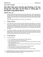
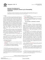
Constants of the Machine:
Absorption of Porcelain and Plaster Base Plate—minimum of 40 g in 24 h. For
rate of absorption of base plates see 6.2.3.2.
Dimension of Base Plate—25 mm [1 in.] in thickness by 100 mm [4 in.] in
diameter.
Dimensions of Disk—0.8 to 12.7 mm [1⁄32 to 1⁄2 in.] in thickness by 76 mm
[3 in.] in diameter.
Speed of Vertical Shaft—One revolution in 6 min, 40 s.
Torque on Disk when Bob Reading is 100—1.41 N·m.
FIG. 2 Emley Plasticimeter
6.2 Apparatus:
6.2.1 Determine the plasticity of lime putty using the
plasticimeter shown in Fig. 2.4
6.2.2 Cleaning and Care of Base Plates—Base plates may
be made of porcelain or plaster. In making the plasticity
determinations, much of the success attainable depends upon
the condition of the base plates. In the case of porcelain plates
which are reused, improper cleaning results in clogging of the
pores with reduction in the rate of absorption. After a porcelain
plate has been used, wipe the excess lime off and immerse the
plate in clear water for not less than 2 h, after which transfer it
without drying to a dilute solution of hydrochloric acid (HCl,
1 + 9) where it shall be kept immersed for another 2 h. Then
transfer to a receptacle containing running water for at least
1 h. The plate is then free of acid. After the removal of excess
water, place the plate in an oven overnight at a temperature of
between 100 and 110°C for drying. Before using, cool the plate
to room temperature. In the case of plaster base plates, dry the
base plates prior to use in plasticity or absorption testing in an
oven at a temperature between 37.8 and 48.9°C until they
achieve a constant weight. Before using, cool the plaster plate
NOTE 3—Most lime hydrates will require 500 to 600 mL of water to
produce a putty of proper consistency for this test if 600 g of lime are used.
5.3.3 Consistency
Determination—To
determine
consistency, place the mold with its larger end resting on the
glass base plate and fill with the lime putty. Then strike off the
putty flush with the top of the mold. Center the lime putty,
confined in the ring mold resting on the plate, under the rod of
the modified Vicat apparatus (Fig. 1). Bring the plunger end, C,
in contact with the surface of the lime putty and take an initial
reading. Release the rod and take the final reading 30 s after the
plunger is released. The lime putty is of standard consistency
when a penetration of 20 6 5 mm is obtained. Record both the
total amount of water required to bring the putty to standard
consistency and the actual penetration. Proceed with the
plasticity determination in accordance with 6.3.
5.4 Precision and Bias:
5.4.1 The precision and bias of this test method has not been
determined.
6. Plasticity of Lime Putty
6.1 Significance and Use:
6.1.1 This test method provides a measure of the degree of
stiffening of lime putty of standard consistency as water is
withdrawn from it by a standard suction base plate.
6.1.2 Plasticity is an important property when applying
mixtures containing lime putty to porous or absorptive surfaces
such as in plastering, stuccoing, and masonry construction.
4
The sole source of supply of the Emley Plasticimeter known to the committee
at this time is Geotest Instrument Corporation, 910 University Place, Evanston, IL
60201, USA. If you are aware of alternative suppliers, please provide this
information to ASTM International Headquarters. Your comments will receive
careful consideration at a meeting of the responsible technical committee 1, which
you may attend.
3
C110 − 16´1
and start the motor. It is essential that the motor be started
exactly 120 s after the first portion of the paste has been placed
in the mold. Record the time when the first portion of paste is
placed in the mold as zero time; the motor is therefore started
at 2 min. Take care to protect the specimen from drafts during
the test.
6.3.2 Record the scale reading at 1 min intervals until the
test is completed. Consider the test complete when: (1) the
scale reading reaches 100, (2) any reading is less than the one
before, or (3) the scale reading remains constant for three
consecutive readings (2 min) and the specimen has visibly
ruptured or broken loose from the base plate. Note the time and
the scale reading at the end of the test.
to room temperature in a dessicator charged with a drying
agent. If the plate is not to be used immediately after reaching
room temperature, continue to store the plate in the dessicator
until such time that it is to be used. Plaster base plates shall not
be reused after plasticity, total absorption, or rate of absorption
testing (see 6.2.3).
6.2.3 Absorption of Plasticimeter Base Plates:
6.2.3.1 Total Absorption—Plasticimeter base plates when
immersed in water at room temperature for a period of 24 h
shall absorb not less than 40 g of water. Before making the
determination, dry the porcelain plates overnight in an oven at
a temperature between 100 and 110°C and permit to cool to
room temperature. Dry the plaster plates in an oven at a
temperature between 37.8 and 48.9°C until they achieve a
constant weight and permit to cool to room temperature in a
dessicator charged with a drying agent. After immersion and
before weighing either porcelain or plaster plates, wipe off the
excess water with a damp cloth.
6.2.3.2 Rate of Absorption (Note 4)—When tested over an
area 70 mm [23⁄4 in.] in diameter, the water absorbed by either
porcelain or plaster base plates shall be in accordance with the
following:
Time, min
1
2
3
4
5
6.4 Calculation:
6.4.1 Calculate the plasticity figure as follows:
P 5 =F 2 1 ~ 10T !
2
(1)
where
P = plasticity figure,
F = scale reading at the end of the test, and
T = time in minutes from the time when the first portion of
paste was put in the mold to the end of the test.
Water Absorbed, mL
6.5 Precision and Bias:
6.5.1 The precision of this test method is based on interlaboratory studies conducted in March and October of 2007. To
determine interlaboratory and intralaboratory precision, one
operator from each of ten different laboratories tested three
different dolomitic Type S hydrated lime samples and one
dolomitic Type N hydrated lime sample made into lime putty
of standard consistency for Final Vicat Penetration (mm) and
Calculated Plasticity Figure (Emley Units). Each laboratory
obtained three replicate test results for each of the supplied
materials.6 Statistical summaries of the testing results are
shown in Tables 1 and 2.
6.5.1.1 Repeatability—Two test results obtained within one
laboratory shall be judged not equivalent if they differ by more
than the “r” value for that material; “r” is the interval
representing the critical difference between two test results for
the same material, obtained by the same operator using the
same equipment on the same day in the same laboratory.
6.5.1.2 Reproducibility—Two test results should be judged
not equivalent if they differ by more than the “R” value for that
material; “R” is the interval representing the difference between two test results for the same material, obtained by
different operators using different equipment in different laboratories.
6.5.1.3 Any judgment in accordance with statements 6.5.1.1
or 6.5.1.2 would have an approximate 95 % probability of
being correct. To judge the equivalency of two test results, it is
recommended to choose the material closest in characteristics
to the test material (Type S or Type N hydrated lime).
6.5.2 Bias—At the time of the studies, there was no accepted reference material suitable for determining the bias for
this test method, therefore no statement on bias can be made.
8 to 14
5 to 71⁄2
4 to 61⁄2
4 to 6
31⁄2 to 51⁄2
(1) Plaster plates designated for rate of absorption testing
shall be statistically representative of all plates manufactured
for that purpose and made from one manufacturing batch run.
Plaster plates selected for rate of absorption testing may not be
re-dried and used for plasticity testing. Porcelain plates designated for rate of absorption testing shall be individually tested
and may be re-dried and used for plasticity testing (see 6.2.2).
NOTE 4—A convenient apparatus for determining the rate of absorption
consists of a buret sealed onto an inverted glass funnel from which the
stem has been removed. The diameter of the larger end of the funnel shall
be ground so as to be 70 mm [23⁄4 in.] in internal diameter. The funnel may
be attached to the plate on which the measurement is being made by
melted paraffin. The paraffin should not be too hot. A little experience will
indicate when it is of the proper consistency. Alternative apparati
manufactured of polycarbonate, metal, and other materials are acceptable.5
6.3 Plasticity Determination:
6.3.1 Lubricate a ring mold such as is described in 5.2.2
with a thin film of water, place on a porcelain base plate (see
6.2.2 and 6.2.3) or a disposable plaster base plate (see 6.2.3),
fill with the paste which has been adjusted to standard
consistency as described in 5.3.3, and strike off level. Remove
the mold by raising it vertically without distorting the paste.
Center the base plate and paste in the instrument and turn the
carriage up by hand until the surface of the paste is in contact
with the disk and the distance between the disk and the top of
the base plate is 32 mm [11⁄4 in.]. Throw the carriage into gear
5
Godbey, Richard J. and Thomson, Margaret L., “Standardized Laboratory
Apparatus for Measuring Emley Baseplate Rate of Absorption,” Rochell Jaffe, Ed.,
Proceedings: 2005--International Building Lime Symposium, Michael Tate,
Chairperson, National Lime Association, Arlington, VA, ISBN 0-9767621-0-2.
6
Supporting data have been filed at ASTM International Headquarters and may
be obtained by requesting Research Report RR:C07-1005.
4
C110 − 16´1
TABLE 1 Final Vicat Penetration (mm)
MATERIAL
Type S Hydrated Lime
Samples A, C, F
Type S Hydrated Lime
Samples B, E, G
Type S Hydrated Lime
Samples D H I
Type N Hydrated Lime
Average
Reproducibility
Standard
Deviation
sR
2.81
Repeatability
Limit
Reproducibility
Limit
χ¯
19.7
Repeatability
Standard
Deviation
sr
2.76
r
7.7
R
7.9
18.4
2.13
2.53
5.9
7.1
18.4
2.83
2.83
7.9
7.9
17.8
2.59
2.59
7.3
7.3
TABLE 2 Calculated Plasticity Figure (Emley Units)
MATERIAL
Type S Hydrated Lime
Samples A, C, F
Type S Hydrated Lime
Samples B, E, G
Type S Hydrated Lime
Samples D H I
Type N Hydrated Lime
Average
Reproducibility
Standard
Deviation
sR
41.62
Repeatability
Limit
Reproducibility
Limit
χ¯
502
Repeatability
Standard
Deviation
sr
22.70
r
64
R
117
480
42.93
66.77
120
187
381
40.52
49.11
114
138
438
25.06
53.51
70
150
To judge the equivalency of two test results, it is recommended
to choose the material closest in characteristics to the test
material (Type S or Type N hydrated lime).
7.2.8 In any case requiring a remixing interval, any mortar
adhering to the side of the bowl shall be quickly scraped down
into the batch prior to remixing.
7. Water Retention of Hydrated Lime
7.3 Consistency:
7.3.1 Apparatus—The flow table and mold used for the
measurement of consistency of the mortar shall conform to
Specification C230/C230M.
7.3.2 Procedure—Carefully wipe dry the flow table top and
place the flow mold at the center. Immediately after completing
the mixing operation, fill the mold with mortar gently pressed
into place by the finger tips to ensure uniform filling free of
voids. Smooth off the mortar level with the top of the mold by
aid of a trowel, and remove the mold. Immediately drop the
table through a height of 13 mm [1⁄2 in.], 25 times in 15 s. The
flow is the resulting increase in diameter of the mortar mass,
expressed as the percentage of the original diameter. The
mortar may be adjusted, if the flow is below 100 %, by
additions of water until the flow is within the range from 100
to 115 %. Make each adjustment by returning the mortar to the
original mixing bowl, add water, and then mix at medium
speed (285 6 10 r/min) for 30 s. If the flow of the original
mortar is greater than 115 %, prepare a new batch.
7.1 Significance and Use:
7.1.1 This test method measures the ability of the hydrated
lime in a plastic mix with sand to retain water, and hence retain
consistency of the mix, when subjected to an applied suction.
This ability, measured as a percent of the original consistency,
is indicative of the workability to be expected in a masonry
mortar containing the lime.
7.2 Proportioning and Mixing:
7.2.1 Apparatus—The apparatus used shall conform to
Practice C305.
7.2.2 Proportions—The mortar tested shall be composed of
500 g of lime and 1500 g of standard sand conforming to 8.2.3.
If hydrated lime putty is used, use that weight of putty that is
equivalent to 500 g of dry hydrated lime.
7.2.3 Mechanical Mixing:
7.2.3.1 Place the dry paddle and the dry bowl in the mixing
position in the mixer.
7.2.3.2 Place a measured quantity of water in the bowl.
7.2.3.3 Add the lime to the water, then start the mixer and
mix at slow speed (140 6 5 r/min) for 30 s.
7.2.4 Add the entire quantity of sand slowly over a 30 s
period while mixing at slow speed.
7.2.5 Stop the mixer, change to medium speed (285 6
10 r ⁄min) and mix for 30 s.
7.2.6 Stop the mixer and let the mortar stand for 11⁄2 min.
(During the first 15 s of this interval, quickly scrape down into
the batch any mortar that may have collected on the side of the
bowl, then for the remainder of this interval cover the bowl
with the lid.)
7.2.7 Finish the mixing for 1 min at medium speed.
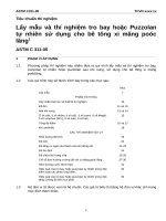
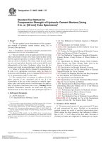
7.4 Water Retention Test:
7.4.1 Apparatus—The equipment shall conform to the apparatus used for the water retention test in Specification C91
(see Fig. 3).
7.4.2 Procedure:
7.4.2.1 Adjust the vacuum regulator to maintain a vacuum
of 51 6 3 mm as measured on the vacuum gauge. Seat the
perforated dish on the greased gasket of the funnel. Place a
wetted filter paper in the bottom of the dish. Turn the stopcock
to apply the vacuum to the funnel and check the apparatus for
leaks and to determine that the required vacuum is obtained.
Then turn the stopcock to shut off the vacuum from the funnel.
5
FIG. 3 Vacuum Gauge Apparatus Assembly for Water Retention Test
C110 − 16´1
6
C110 − 16´1
8.2.3 The sand shall be a blend of equal parts by weight of
graded Ottawa sand and standard 20-30 Ottawa sand. The
fineness of graded Ottawa sand and standard 20-30 sand may
be checked by using the methods described in Specification
C778.
7.4.2.2 Immediately after the final consistency test (7.3.2),
return all of the mortar to the bowl and remix the entire batch
for 15 s at medium speed. Immediately after remixing the
mortar, fill the perforated dish with the mortar to slightly above
the rim. Tamp the mortar 15 times with the tamper. Apply ten
of the tamping strokes at approximately uniform spacing
adjacent to the rim of the dish and with the long axis of the
tamping face held at right angles, to the radius of the dish.
Apply the remaining five tamping strokes at random points
distributed over the central area of the dish. The tamping
pressure shall be just sufficient to ensure filling of the dish. On
completion of the tamping, the top of the mortar should extend
slightly above the rim of the dish. Smooth off the mortar by
drawing the flat side of the straightedge (with the leading edge
slightly raised) across the top of the dish. Then cut off the
mortar to a plane surface flush with the rim of the dish by
drawing the straightedge with a sawing motion across the top
of the dish in two cutting strokes, starting each cut near the
center of the dish. If the mortar is pulled away from the side of
the dish during the process of cutting off the excess mortar,
gently press the mortar back into contact with the side of the
dish using the tamper.
7.4.2.3 Turn the stopcock to apply vacuum to the funnel.
After suction for 60 s, quickly turn the stopcock to expose the
funnel to atmospheric pressure. Immediately slide the perforated dish off the funnel, touch it momentarily on a damp cloth
to remove droplets of water, and set the dish on the table. Then,
using the bowl scraper (rubber scraper as specified in Practice
C305), plow and mix the mortar in the dish for 15 s. Upon
completion of mixing, place the mortar in the flow mold and
determine the flow. Carry out the entire operation without
interruption and as quickly as possible. Not more than 30 min
should be required for completion, starting from the completion of the mixing of the mortar for the first flow determination.
7.4.3 Calculation:
7.4.3.1 Calculate the water retention value for the mortar as
follows:
Water retention value 5 ~ A/B ! 3 100
8.3 Preparation of Mortar:
8.3.1 Proportions for Mortar—Lime-based mortars for
measurement of air entrainment shall be proportioned to
conform, in batch size, to the unit weights by volume of
cementitious material and aggregate as shown in Table 3. The
cement shall conform to Specifications C150, C595, or C1107,
and the hydrated lime to Specification C207. The quantity of
water, measured in millilitres, shall be such as to produce a
flow of 110 6 5 % as determined by the flow table. Proportions
for the generally used batch sizes based on Table 3 material
unit weight shall contain the weights as prescribed in Table 4.
8.3.2 Mixing of Mortars—Mix the mortar in accordance
with the procedure for mixing pastes in Practice C305.
8.3.3 Determination of Flow—Determine the flow in accordance with the Procedure section of Test Method C109/
C109M.
8.4 Procedure:
8.4.1 If the mortar has the correct flow, use a separate
portion of the mortar for the determination of entrained air. The
amount of air entrainment shall be determined by one of two
methods. The density method determines air content from the
measured density of the mortar, the known density of
constituents, and the mixture properties. The air pail method
measures air content using Test Method C231.
8.4.2 Density Method:
8.4.2.1 Apparatus: Scales, Sieves, Glass Graduates,
Tamper, Measure, Straightedge, Spatula, Tapping Stick, and
Spoon, conforming to the requirements given in Test Method
C185.
8.4.2.2 Procedure:
(1) Fill a 400 ml measure with the mortar sample in
accordance with Test Method C185.
(2) Determine the weight of mortar in the measure.
8.4.2.3 Calculation—Calculate the air content of the mortar
and report it to the nearest 0.1 % as follows:
(2)
where:
A = flow after suction, and
B = flow immediately after mixing.
7.5 Precision and Bias:
7.5.1 No precision data are available due to the limited use
of this test method. Therefore, users are advised to develop
their own laboratory precision.
D 5 ~ W 1 1W 2 1W 3 1V w ! /
(3)
@ ~ W 1 /S 1 ! 1 ~ W 2 /S 2 ! 1 ~ W 3 /S 3 ! 1V w # A 5 100 2 ~ W m /4D !
8. Air Entrainment
8.1 Significance and Use:
8.1.1 Hydrated lime, particularly that containing an airentraining additive, used in masonry mortar may contribute to
the air content of the mortar. Certain specifications and
applications of mortar place a limit on this air content.
TABLE 3 Unit Weights and Apparent Specific Gravities
Materials
Portland Cement
Blended Cement
Hydraulic Cement
Hydrated Lime
Blended Ottawa Silica Sand
8.2 Apparatus:
8.2.1 Flow Table, conforming to the requirements prescribed in Specification C230/C230M.
8.2.2 Mixing Apparatus, conforming to the requirements as
prescribed in Practice C305.
A
Unit weight,
kg/m3 [lb/ft] 3A
Specific
Gravity
1,504 [94]
3.15
obtain from purchaser
obtain from purchaser
640 [40]
2.30
1,280 [80]
2.65
The unit weight values listed for cementitious materials are assumed values
commonly used in construction practice.
7
C110 − 16´1
TABLE 4 Weight of Materials for Mortar Batch
Mortar
Type
Proportions
by
Volume
Portland
Cement
(g)
Hydrated
Lime
(g)
Blended Ottawa
Silica Sand
(g)
M
S
N
O
Lime/Sand
1:1⁄4 :33⁄4
1:1⁄2 :41⁄2
1:1:6
1:2:9
1:3
470.0
376.0
282.0
188.0
62.5
100.0
150.0
200.0
300.0
1,500
1,440
1,440
1,440
1,440
where:
D
=
=
W1
W2
=
=
W3
=
Vw
=
S1
=
S2
=
S3
A
=
Wm =
Apply the tamping strokes in such a manner as to only settle
and consolidate the mortar into the bowl without the addition
of voids left by the insertion and removal of the tamper at each
stroke.
8.4.3.3 Precision and Bias—Although precision for the test
method for air content of freshly mixed concrete has been
reported in Test Method C231, the precision of this test method
has not been determined for lime-based mortars. When sufficient data has been obtained and analyzed, a statement of
precision will be provided. In the meantime users of the test
method are advised to develop their own.
SOUNDNESS TESTING
density of air-free mortar,
weight of cement, g,
weight of lime, g,
weight of blended Ottawa sand, g,
water used, mL,
specific gravity of portland cement,
specific gravity of hydrated lime,
specific gravity of blended Ottawa sand,
volume % of entrained air, and
weight of 400 mL of mortar, g.
9. Autoclave Expansion of Hydrated and Hydraulic Lime
9.1 Significance and Use:
9.1.1 Expansion of pressed tablets of hydrated and hydrated
or pozzolanic hydraulic lime generally indicates the presence
of unhydrated oxides of magnesium and calcium or other
expansive material. The relation of the degree of expansion in
this test method to field performance has not been determined.
9.2 Apparatus:
9.2.1 Mold and Press—A steel mold capable of producing a
press tablet at least 0.032 m [1.25 in.] in diameter and 0.006 m
[0.25 in.] thick, and able to sustain at least 88.9 kN
[20 000 lbf] pressure from a suitable press. It should be
provided with a release jig also.
9.2.2 Autoclave, capable of holding 1034 kPa [150 psi] for
2 h.
9.2.3 Micrometer, dial-type, capable of measuring 2.54 µm
[0.0001 in.].
9.2.4 Microscope, with graduated lens for measuring
0.10 mm.
NOTE 5—For lime/sand mortars, W1 and S1 should be dropped from the
calculation.
8.4.2.4 Precision and Bias:
(1) The single operator within laboratory standard deviation has been found to be 0.56 % air content throughout the
range of 8 to 19 % air content. Therefore results of two
properly conducted tests by the same operator on similar
batches of mortar should not differ by more than 1.6 % air
content.
(2) The multilaboratory standard deviation has been found
to be 1.0 % air content throughout the range of 8 to 19 % air
content. Therefore, results of two different laboratories on
similar batches of mortar should not differ from each other by
more than 2.8 % air content (see Test Method C185).
8.4.3 Air Pail Method:
8.4.3.1 Apparatus:
(1) Air Meters—There are two basic operational designs
employing the principle of Boyle’s law. Both types of units are
detailed in Test Method C231.
(2) Calibration Vessel, Spray Tube, Tamping Rod, Mallet,
Strike-Off Bar, Funnel, and Water Measure, conforming to the
requirements given in Test Method C231.
8.4.3.2 Procedure:
(1) Calibrate the air meter using procedures described in
Test Method C231 Section 5.
(2) Fill the air meter and determine air content by using the
method detailed in Test Method C231 Section 8, except that for
Type B meters with a volume of 1 L or less, there shall be no
use of an internal vibrator as required in Test Method C231 and
described in Practice C192/C192M.
(3) When using Type B meters with a volume of 1 L or less,
compact the mortar into the bowl by tamping the mortar 15
times with a tamper meeting the requirements of Test Method
C185 Section 5. Apply ten of the tamping strokes near the
outside circumference of the mortar bowl evenly spaced at
right angles to the radius of the bowl and five of the tamping
strokes at random points distributed in the center of the bowl.
9.3 Procedure for Expansion Testing:
9.3.1 Hydrated Lime—Weigh out 15 g of hydrated sample,
place in the mold, and press into a tablet. Press to 33.4 kN
[7500 lbf] for 10 s, then increase pressure to 88.9 kN
[20 000 lbf] or more. Hold for 10 s before releasing. Press
tablet from mold with jig and draw three diameter lines across
the surface of the tablet using a lead pencil. Draw two diameter
lines normal to each other and draw the third bisecting the 90°
angles of the other two. Measure the diameters with a dial
micrometer and place the tablet on the autoclave rack. Use
aluminum foil to protect the tablets from water dripping.
Autoclave at 862 to 1034 kPa [125 to 150 psi] for 2 h. Begin
timing when the pressure reaches 345 kPa [50 psi]. After the
autoclaving interval, allow the autoclave to cool, remove the
tablet, and remeasure the diameters. Calculate the average
percent expansion of the tablet from the before and after
measurements.
9.3.2 Hydrated and Pozzolanic Hydraulic Lime—Follow
the method of 9.3.1 with the exception use 25 g of material.
Place in the mold with 5 g of potable water and mix well. If it
is not possible to mix with water in the mold, do so in a suitable
container, ensuring that all of the material is transferred to the
mold. Press to 6.89 kN and hold for 10 s before releasing.
9.4 Expansion of Hydrated Lime-Portland CementAggregate:
8
C110 − 16´1
10.3.2 Place the specimen and plate on a rack in the steam
bath so that water is not in contact with the specimen to be
tested. Provide a sloping cover above the specimen to prevent
condensed steam from dripping onto the surface of the specimen. Raise the temperature of the water in the steam bath to
boiling and maintain at boiling for 5 h. Remove the specimens
from the bath and examine for pops and pits.
10.3.3 The pitting potential of hydrated lime can be determined in conjunction with autoclave expansion as in 9.3.1.
However, it is not necessary to measure diameter, if only the
pitting potential is to be determined. After following the
procedure for expansion in 9.3.1, examine the pressed tablet
under the measuring microscope, and count and measure the
pits in millimetres.
9.4.1 Materials:
9.4.1.1 Standard Cement—Type I or Type II portland cement.
9.4.1.2 Standard Aggregate—Pulverized limestone, minus
212 µm (No. 70) sieve, having less than 0.5 % silicon dioxide
(SiO2).
9.4.2 Procedure:
9.4.2.1 Test Tablet—Make up a pressed tablet in accordance
with the procedure outlined in 9.3.1 using the following
mixture for the sample:
Standard portland cement
Hydrated lime
Standard aggregate (pulverized limestone)
14 g
8g
72 g
Blend the mix until homogeneous.
9.4.2.2 Standard Tablet—Make up a pressed tablet in accordance with the procedure outlined in 9.3.1 using the following
mixture for the sample:
Standard portland cement
Standard aggregate (pulverized limestone)
APPLICATION TESTING
11. Slaking Rate of Quicklime
7g
16 g
11.1 Significance and Use:
11.1.1 The temperature rise in 30 s is a measure of the
reactivity of the softer-burned portion of the quicklime. Total
slaking time provides a measure of the overall degree of
reactivity of the material. Total temperature rise is largely
dependent on the available lime content of the sample.
11.1.2 These slaking parameters provide an indication of the
performance of the quicklime to be expected in industrial
slaking systems. Slaking characteristics have an effect on lime
slurry properties such as settling characteristics, viscosity,
particle size, and reaction rate.
Blend the mix until homogeneous.
9.4.2.3 Autoclave and calculate expansions of the test tablet
and the standard tablet in accordance with 9.3.1.
9.4.2.4 Determine the autoclave expansion of hydrated lime
for masonry purposes by subtracting the average percent
expansion of the standard tablet from the sample tablet.
9.5 Precision and Bias:
9.5.1 No precision data are available due to the limited use
of this test method. Therefore, users are advised to develop
their own laboratory precision. No statement is being made
about the bias of this test method.
11.2 Apparatus:
11.2.1 Mechanical Stirrer, speed 400 6 50 r/min, fitted with
a special stirring rod.
11.2.2 Modified Dewar Flask, 665 mL, fitted with special
rubber gasket covers.
11.2.3 Thermometer, dial-type, 0 to 100°C range in 1°C
increments or thermocouple with a response time equivalent to
or faster than the dial thermometer.
11.2.4 Torsion Balance.
11.2.5 Sieve, 203 mm [8-in.], 3.35 mm (No. 6), conforming
to Specification E11.
11.2.6 An apparatus essentially the same as that illustrated
in Figs. 4 and 5 shall be used. The apparatus consists of a
covered reaction container fitted with a mechanical stirrer and
thermometer. The quicklime charge shall be stirred with a
mechanical stirrer fitted with a stainless steel rod, the end of
which is formed into a loop to follow the contour of the
reaction container. The vacuum reaction flask shall be provided
with a cover consisting of two circular pieces of gasket rubber
sheet, approximately 3 mm [1⁄8 in.] thick. The first piece is
provided with a single radial slot that slides over the stirring
rod and the thermometer. The second piece (top) has a similar
slot plus a hole to provide for the dial thermometer. When the
two cover pieces are in place, the slot on the lower piece is at
right angles to the slot on the upper piece with the thermometer
stem extending through the lower slot. The apparatus may be
assembled by any convenient supporting equipment.
10. Popping and Pitting of Hydrated Lime
10.1 Significance and Use:
10.1.1 Pops and pits are caused by the hydration and
expansion of coarse particles of unhydrated lime or limeimpurity reaction products present in the hydrated lime. The
level of popping and pitting in the sample is indicative of the
potential for the appearance of surface defects in plastering
applications.
10.2 Gauging Plaster:
10.2.1 The gauging plaster used for the popping and pitting
test shall conform to the Test Methods section of Specification
C28/C28M and shall have a setting time of not more than 1 h
when tested in accordance with Test Methods C472. Test the
gauging plaster without lime in the manner described in 10.3 to
ensure its freedom from pops and pits. If any pops or pits are
found, provide another lot of gauging plaster that is free of
pops and pits when subjected to this test.
10.3 Procedure:
10.3.1 Mix 100 g of hydrated lime with sufficient water to
bring to such a consistency as to give a penetration of 20 6
5 mm when tested in accordance with 5.3.3. Mix into this
putty, 25 g of gauging plaster (10.2.1), adding more water as
required to maintain workable consistency. Spread on a glass
plate to make a pat at least 150 by 200 mm [6 by 8 in.] by
approximately 3 mm [1⁄8 in.] in thickness. Trowel to a smooth
finish. Allow to stand overnight.
11.3 Procedure:
9
C110 − 16´1
FIG. 4 Slaking Reactivity Apparatus
the sample pass a 3.35 mm (No. 6) sieve, but all of the sample,
including the plus 3.35 mm (plus No. 6) fraction, must be used
in the test.
11.3.2 Slaking Rate—Adjust the temperature of about
500 mL of distilled water in accordance with the schedule
given in Table 5, and add the specified amount to the Dewar
flask. Set the agitator revolving at 400 6 50 r/min. The
temperature of the water in the flask must be 60.5°C of the
desired temperature. Quarter and weigh out the required
amount of the prepared quicklime sample. Add the quicklime
to the water without delay and simultaneously begin timing.
Put the covers in place immediately. Take a reading at each 30
s interval.
11.3.3 Continue readings until less than 0.5°C temperature
change is noted in each of three consecutive readings. The total
active slaking time will then be the time at which the first of the
three consecutive readings was taken. The temperature at this
time will be considered the final reaction temperature. Subtract
the initial temperature from the final temperature to obtain the
total temperature rise. Subtract the initial temperature from the
temperature at 30 s for the temperature rise in 30 s. Subtract the
initial temperature from the temperature at 3 min for the
temperature rise in 3 min.
FIG. 5 Stirring Rod Detail
TABLE 5 Schedule for Slaking Rate
11.3.1 Prepare the sample of quicklime (as rapidly as
possible to prevent sample deterioration) so that a majority of
the material passes a 3.35 mm (No. 6) sieve. Place the sample
in an airtight container and allow to come to room temperature
before testing. The slaking rate of lime is significantly affected
by the particle size of the sample and must be as close to a 3.35
mm (No. 6) sieve as possible. It is not necessary that 100 % of
Temperature of water, °C
Quantity of water, mL
Quantity of quicklime, g
A
Material to Be Tested
Dolomitic
High Calcium
40
25A
400
400
120
100
Initial temperature of 40°C may be used, provided the report of results states the
initial temperature.
10
C110 − 16´1
12.3 Apparatus:
12.3.1 Reflectometer.
12.3.2 Dry Powder Press (See Fig. 6)—Instructions, as
11.3.4 Residue of Quicklime—Allow slurry from the
slaking/reactivity test to continue slaking for a minimum of
15 minutes. Stop the stirrer and remove the Dewar flask,
washing the slurry residue from the stirring rod into the flask.
Carefully and slowly pour the residue through a 600 µm (No.
30) sieve (Note 6). Wash the slurry through the screen with a
spray of tap water, being careful not to lose any residue over
the top of the sieve. Continue washing until all slurry is
through the sieve and all that remains are residue particles. Blot
dry the bottom of the sieve with a paper towel and then place
in a drying oven for 1 h at 105 6 5°C. Remove from the oven,
cool, collect the dried residue, and weigh.
Grams of Residue
3 100 5 % Residue
Weight of Sample
NOTE 6—The quicklime being slaked is very hot and highly basic.
Caution must be taken not to let this material contact the eyes or skin as
this may cause severe thermal or chemical burns, or both.
Calculation:
11.4 Report:
11.4.1 Record the actual temperature rise and plot a suitable
curve showing temperature rise as the ordinate and time as the
abscissa. The results may also be reported as:
11.4.1.1 Temperature rise in 30 s (or at any other designated
time) in degrees Celsius,
11.4.1.2 Total temperature rise in degrees Celsius, and
11.4.1.3 Total active slaking time in minutes.
FIG. 6 Dry-Powder Press
supplied by the manufacturer, for preparation of the sample and
use of the powder press shall be explicitly followed.
12.3.3 White Porcelain Standard Plaque, to be used as
secondary standard.
11.5 Precision and Bias:
11.5.1 Twelve laboratories cooperated in the testing of five
high calcium quicklimes and four dolomitic quicklimes thereby
obtaining the repeatability (r) and reproducibility (R) (Practice
E691) data contained in Table 6.7
12.4 Reagent:
12.4.1 Barium Sulfate (BaSO4)—Use Eastman Kodak8
Chemical No. 60919, white reflectance standard only.
12.5 Calibration and Standardization:
12.5.1 Zero Scale Calibration (bottom of scale standardization):
12.5.1.1 Place the black glass provided with the instrument
over the specimen port, so that the shiny side is towards the
opening. The glass should be positioned so that no light
escapes from the black glass-opening interface.
12.5.1.2 The processor is then adjusted to read zero reflectance.
12.5.2 Standardizing of the White Standard (standardization
of the upper part of the scale):
12.5.2.1 A primary standard pellet (barium sulfate) which is
free from surface flaws should be positioned over the specimen
port so that no light can escape at the pellet-opening interface.
12.5.2.2 The Eastman Kodak barium sulfate reflectance
standard is provided with reflectance values at various wavelengths. Since some variation is possible between lots of
BaSO4, the values used to standardize the reflectometer must
be calculated. A normal Y value will be between 99.0 and 98.5,
depending on the lot number.
12.5.2.3 After this has been accomplished, a reading of the
white standard plaque can be taken and the values of X, Y, and
Z recorded. This plaque can then be used as a secondary
TABLE 6 Precision Data
Material
High Calcium
High Calcium
Dolomitic
Dolomitic
Labs
12
11
10
9
Results in °C Rise
Time
Range Tested
30 s
3 min
30 s
3 min
12.3–44.4
32.1–56.1
3.6–12.0
21.2–36.4
r
R
1.56
1.72
1.38
1.62
4.21
4.72
2.84
3.72
11.5.2 Due to the lack of a recognized industry standard, the
bias of this test method has not been determined. The variety of
reporting options also complicates obtaining a suitable bias
statement.
12. Dry Brightness of Pulverized Limestone
12.1 Summary of Test Method:
12.1.1 A sample of the dry material is compressed and its
reflectance measured on a reflectometer that has previously
been standardized.
12.2 Significance and Use:
12.2.1 This test method provides a measure of the
reflectance, or whiteness, or both of ground calcium carbonate
products by comparison with a standard, using green and blue
filters.
8
Registered trademark.
The sole source of supply of the apparatus known to the committee at this time
is Eastman Kodak Co., 343 State St., Rochester, NY 14650. If you are aware of
alternative suppliers, please provide this information to ASTM International
Headquarters. Your comments will receive careful consideration at a meeting of the
responsible technical committee,1 which you may attend.
9
7
Supporting data have been filed at ASTM International Headquarters and may
be obtained by requesting Research Report RR:C07-1003.
11
C110 − 16´1
13.3.1 This test method is useful for comparison and acceptance testing of limestone for applications where fine ground
limestone is desired.
standard for future standardizations. This reduces the necessity
of making a barium sulfate pellet for every test series.
12.6 Procedure:
12.6.1 The reflectometer must be given ample warm-up
time prior to the sample readings.
12.6.2 The reflectometer must first be standardized; this
consists of standardization of the bottom of the scale and
standardization of the upper part of the scale.
12.6.3 Sample pellets should then be pressed (Note 7)
following manufacturer instructions explicitly (Note 8).
13.4 Apparatus:
13.4.1 Jar Mill, operated at 110 6 10 r/min.
13.4.2 Mill Jar, ceramic 14 cm [51⁄2 in.] diameter by 21.2
cm [63⁄4 in.] high.
13.4.3 Grinding Media, 160 6 1 g total, consisting of seven
ceramic 21 by 21 mm [13⁄16 by 13⁄16 in.] cylindrical grinding
media (about 23 g each).
13.4.4 The sieves used shall conform to the requirements of
Specification E11.
13.4.5 Weights and weighing devices, shall conform to the
requirements of Specification C1005.
13.4.6 Drying Oven, capable of maintaining 100°C.
13.4.7 A Chipmunk Crusher, capable of breaking large rocks
to less than 6.35 mm [1⁄4 in.].
13.4.8 Riffle Sample Splitter, open pan, 12.7 mm [1⁄2 in.]
chute width.
13.4.9 Stopwatch.
NOTE 7—Ground products with more than 0.5 % residue on a 45 µm
(No. 325) screen will require special care in preparing the sample cup. The
coarser the product, the harder to obtain a compact, smooth surface.
NOTE 8—Some reflectometers and spectrophotometers can measure
reflectance with the powder sample in a horizontal position, thus eliminating the necessity to prepare a sample pellet. Also, coated ground
limestones are difficult to pelletize. Loose powder samples should be
smoothed in a convenient sized container until the surface is level and free
from cracks and other surface defects.
12.6.4 After the reflectometer has been standardized, the
sample pellets are centered beneath the opening and positioned
so that no light escapes from the pellet-opening interface.
12.6.5 The samples are then read for X, Y, Z, L, a, and b
values. These values are recorded.
12.6.6 To determine if the values of the reflectometer have
drifted, the white standard (either the barium sulfate pellet or
the porcelain plaque) is placed over the specimen port and
read. Values should be the same as those placed in the
processor during the standardization procedure.
13.5 Reagents and Materials:
13.5.1 Milling Solution, a 0.1 % solution of acrylate based
dispersant. The dispersant chosen should not increase the
solubility of limestone in water.10
13.6 Sampling:
13.6.1 Sample in accordance with Practice D75.
13.6.2 Reduce the sample in accordance with Practice C702
and prepare by sieving out the material that passes a 850 µm
(No. 20) sieve11 and is retained on a 425 µm (No. 40) sieve.11
12.7 Report:
12.7.1 The Y value is recorded as the dry brightness of that
specific limestone.
13.7 Procedure:
13.7.1 Weigh seven grinding media, make adjustments (by
substitutions or filing) to bring total weight to 160 g 6 1 g.
13.7.2 If the jar mill has provision for automatic shut-off, set
it for 5000 revolutions, otherwise determine the mill r/min by
counting the revolutions in an accurately timed period (using
stopwatch) and then calculate the exact time required for 5000
revolutions.
13.7.3 Weigh out 20 6 0.01 g of dried 20 by 40 mesh
limestone. Record actual weight as W1.
13.7.4 Add 180 mL of milling solution to clean and empty
mill jar.
13.7.5 Add the seven grinding media and quantitatively
transfer the limestone sample to the mill jar and secure the top.
13.7.6 Place the mill jar on the mill rollers and operate the
mill for the exact time required to make 5000 revolutions.
13.7.7 Quantitatively transfer the limestone slurry from the
jar mill by rinsing the entire contents onto a coarse sieve (for
example, 3.35 mm (No. 6)) and an underlying 75 µm (No. 200)
sieve. Rinse the media and coarse sieve and separate the sieves.
13.7.8 Wet sieve the sample remaining on the 75 µm (No.
200) sieve to remove the finer material.
13.7.9 Dry and weigh the residue from the 75 µm (No. 200)
sieve and record as W2 (to the nearest 0.01 g).
12.8 Precision and Bias:
12.8.1 The same instrument, operator, and standard should
reproduce 60.2 %. Different instrument (Note 9), operators,
and standard should agree 61.0 %.
NOTE 9—It is recognized that there are various manufacturers of
reflectometers, and testing has been undertaken to relate X, Y, and Z
tristimulus color values from one instrument to another. If results of this
comparison testing are desired, please contact the Pulverized Limestone
Association.
13. Limestone Grindability Determination by Laboratory
Ball Mill Method
13.1 Scope:
13.1.1 This test method is used to determine the relative
grindability or ease of pulverization of limestones of differing
hardness and to report this as a grindability index.
13.1.2 This test method is applicable to all types of limestone.
13.2 Summary of Test Method:
13.2.1 Limestone of a specified size range is wet ground in
a ball mill therein receiving a specified amount of grinding
energy. The amount of minus 75 µm (200-mesh) limestone
produced is measured by wet sieving and reported as the
percent passing 75 µm (200-mesh) after 5000 revolutions. This
is the grindability index.
10
Distilled or deionized water should be used for milling solution or solubility
tests.
11
U.S. Standard Sieves 6, 20, 40, and 200 mesh sizes; 20.3 cm [8 in.] diameter
by 5 cm [2 in.] depth with stainless steel wire cloth.
13.3 Significance and Use:
12
C110 − 16´1
15.2.5 Attach a pressure gauge to the water faucet and a
rubber tubing to the output side of the pressure gauge. On the
other end of the rubber tubing attach the spray nozzle (see
15.2.3).
13.8 Calculation:
13.8.1 Calculate the grindability index (GI) as follows:
GI 5 ~ W1 2 W2 ! /W1 3 100
(4)
13.9 Precision and Bias:
13.9.1 The precision and bias of this test method has not
been determined at this time.
15.3 Slaking Residue of Quicklime:
15.3.1 This test method determines the residue obtained
from slaking quicklime. Residue, in this case is largely
uncalcined limestone or dolomite, overburned quicklime, or
impurities, or a combination of these.
15.3.2 Select a representative 2.5 kg [5-lb] sample of the
quicklime. Break lime selected for this test so as to entirely
pass a 25.0 mm [1-in.] square mesh screen. Test the pulverized
lime as received. Place the sample in a box of wood or of some
material of similarly low thermal conductivity, and an experienced operator should slake it with sufficient water at 21 to
27°C to produce the maximum quantity of lime putty, carefully
avoiding “burning” or “drowning” the lime. Allow it to stand
for 1 h and then wash through an 850 µm (No. 20) sieve by
means of a stream of water from the nozzle attached to a rubber
tubing (see 15.2.5) after adjusting the water pressure to 69 6
1.7 kPa [10 6 0.25 psi]. Do not rub any material through the
sieve. Continue the washing until the residue on the screen
appears to consist entirely of coarse particles, but in no case
continue the washing for more than 30 min. Dry the residue to
constant weight at a temperature of 110 + 5°C and calculate the
percentage residue, based on the original mass of the sample.
14. Settling Rate of Hydrated Lime
14.1 Significance and Use:
14.1.1 This test method provides a measure of the rate of
settling of a hydrated lime slurry, a form in which this material
is frequently used. In some applications a slow settling slurry
is desirable; in others, fast settling is preferred.
14.2 Procedure:
14.2.1 Place 10.0 g of lime hydrate in a 100 mL glassstoppered graduated cylinder (internal diameter about 24 mm).
Wet with 50 mL of carbon dioxide (CO2) free distilled water at
23 6 1.7°C and mix thoroughly by alternately inverting and
righting the cylinder slowly for a period of 2 min. Allow the
graduate and contents to stand at 23 6 1.7°C for 30 min and
then dilute to the 100 mL mark with CO2-free distilled water at
23 6 1.7°C. Mix contents again thoroughly as before and
allow to stand undisturbed at 23 6 1.7°C for 24 h.
14.3 Report:
14.3.1 Report the sedimentation height in millilitres after
1⁄4, 1⁄2, 3⁄4 , 1, 2, 4, and 24 h, reading the bottom of the meniscus.
15.4 Wet Sieve Analysis of Limestone and Hydrated Lime:
15.4.1 This test method determines the particle size distribution of limestone or hydrated lime samples over a set of
desired sieves by washing the material with a controlled spray
of water.
15.4.2 Select the desired sieves and nest them with the
coarsest sieves on top. Determine the mass of a 100 g sample
of the limestone or hydrated lime as received and place it on
the top sieve. Starting with the top sieve, wash the material
through each sieve by means of a stream of water from the
nozzle attached to rubber tubing (see 15.2.5) after adjusting the
water pressure to 69 61.7 kPa [10 6 0.25 psi]. Carefully wash
the sample through each sieve without allowing any splashing
over the sides of the sieve. After the sample is washed through
the top sieve, separate it from the next sieve and repeat the
washing procedure with the next coarsest sieve. When washing
is complete the water should be clear, that is no particles can be
seen in a beaker of the rinse water, but in no case continue
washing last longer than 30 min. Take care not to let water
accumulate on the 75 µm (No. 200) sieve, because the openings will become clogged and the operation cannot be completed in 30 min.
15.4.3 Dry the material retained on each sieve at a temperature of 110 + 5°C for at least one hour, cool and determine the
mass. Report the results of the sieve analysis as follows: (1)
total percentages passing each sieve, (2) total percentages
retained on each sieve, or (3) percentages retained between
consecutive sieves, depending upon the form of the specification for the use of the material under test
15.4.4 Precision and Bias:
15.4.4.1 No precision data are available due to the limited
use of these test methods. Therefore, users are advised to
NOTE 10—Slight variations in results of this test method on a sample
run in different laboratories or by different operators are permissible. The
test is not an absolute one, but is designed to distinguish between fast and
slow settling hydrates.
14.4 Precision and Bias:
14.4.1 No precision data are available due to the limited use
of this test method. Therefore, users are advised to develop
their own laboratory precision.
PARTICLE SIZE ANALYSIS
15. Quicklime Residue and Wet Sieve Analysis of
Limestone and Hydrated Lime
15.1 Significance and Use:
15.1.1 These test methods determine the residue obtained
from quicklime slaking and particle size distributions of
limestone and hydrated lime by washing samples with sprayed
water through sieves.
15.2 Apparatus:
15.2.1 The sieves used shall conform to the requirements of
Specification E11. Preferably the sieves should have a 100 mm
[4-in.] depth.
15.2.2 If sieve calibrations are required, follow the method
as outlined in Test Method C430.
15.2.3 Spray Nozzle, conforming to the requirements of Test
Method C430.
15.2.4 Pressure Gauge shall be 75 mm [3-in.] minimum
diameter, and shall be graduated in 6.9 kPa [1-psi] increments,
and shall have a maximum capacity of 207 kPa [30-psi]. The
accuracy at 69 kPa [10 psi] shall be 61.7 kPa [60.25 psi].
13
C110 − 16´1
equivalent spherical diameter of the individual particles expressed in micrometres, using the principle of sedimentation
and Stokes’ law for particle size determination. It is intended
for use with pulverized limestones with not more than 0.5 %
residue on a 45 µm (No. 325) sieve.
develop their own laboratory precision. No statement is being
made about the bias of these test methods.
16. Sieve Analysis of Dry Limestone, Quicklime, and
Hydrated Lime
16.1 Significance and Use:
16.1.1 This method can be used for hand or mechanical
sieving of dry limestone, quicklime, or hydrated lime samples.
18.2 Apparatus:
18.2.1 Soil Hydrometer, ASTM 152H.
18.2.2 Sedimentation Cylinder, ASTM, 1000 mL capacity.
18.2.3 Rubber Stopper, Size 12.
18.2.4 Thermometer, 0 to 105°C.
18.2.5 Stop Watch.
18.2.6 Regular Clock or Watch.
18.2.7 Mixer.
18.2.8 Water Bath.
18.2.9 Balance.
18.2.10 Watch Glass.
18.2.11 Graph Paper, 3 cycles ì 70 divisions.
18.2.12 Sieve, 45 àm (No. 325), stainless steel cloth, brass
frame, 8-in. diameter.
18.2.13 Sieve, 500-mesh, stainless steel cloth, brass frame,
4-in. diameter, 5-in. tall frame.
16.2 Procedure:
16.2.1 Select the desired sieves and nest them with the
coarsest sieves on top. Obtain a 100 g sample of the material to
be tested and place it on the top sieve. Conduct the sieving
operation by means of a lateral and vertical motion of the sieve
accompanied by a jarring action to keep the sample moving
continuously over the surface of the sieve. Continue sieving
until not more than 1 % of the residue passes any sieve during
1 min. If mechanical sieving is used, the device shall be such
as to impart the type of agitation described in the hand sieving
operation. Continue the shaking for a period of 15 min.
16.2.2 Determine the mass of the residue retained on each
sieve to the nearest 0.1 g. Report the results of the sieve
analysis as follows: (1) total percentages passing each sieve,
(2) total percentages retained on each sieve, or (3) percentages
retained between consecutive sieves, depending upon the form
of the specification for the use of the material under test.
18.3 Reagents:
18.3.1 Particle-Dispersing Agent, (30 mL of 25 % solution
is diluted up to 400 mL with distilled water).
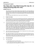
18.4 Procedure:
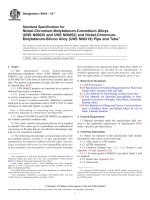
18.4.1 Determine meniscus correction by inserting the hydrometer in the sedimentation cylinder filled to mark with
distilled water. Record the reading at the top of the meniscus
and at the bottom of the meniscus. The difference between the
two readings is the meniscus correction. For example, in Fig. 7,
the correction for the hydrometer used is 1.2. This reading is
added to each R to obtain Rr.
18.4.2 Calibrate the hydrometer by adding 30 mL of the
particle-dispersing solution to the sedimentation cylinder, then
bringing up to the mark with distilled water at 27°C. Mix
thoroughly and take a hydrometer reading (read at the top of
the meniscus). Repeat after cooling the cylinder to 17°C and
adjusting the meniscus so it is on the mark. Assume a
straight-line relationship and draw a line that gives the composite correction factor. This factor is the difference between
the reading and zero. These are the corrections entered in Table
7 and should be determined for each hydrometer. Four factors
are compensated for in the correction factor: (1) Temperature:
Hydrometers and cylinders are calibrated at 20°C; variations
from this temperature produce inaccuracy in the hydrometer
reading; (2) Specific gravity: Addition of dispersant changes
the specific gravity of the solution; (3) Meniscus correction:
Hydrometers are graduated to read at the bottom of the
meniscus but opaque calcium carbonate solutions require
readings at the top of the meniscus; and (4) Hydrometers: In
spite of the supposed similarity in volume of the hydrometers
(ASTM 152H), variations of as much as 1.0-scale divisions
between two similar hydrometers have been noted. The correction factor brings all four into line with one another. It is not
necessary to repeat this calibration unless changing to a
different hydrometer.
18.4.3 Weigh 40 g of sample.
16.3 Precision and Bias:
16.3.1 No precision data are available due to the limited use
of this test method. Therefore, users are advised to develop
their own laboratory precision. No statement is being made
about the bias of this test method.
17. Fineness of Pulverized Quicklime and Hydrated Lime
by Air Permeability
17.1 Significance and Use:
17.1.1 This test method covers the determination of fineness
of pulverized quicklime and hydrated lime using the Blaine air
permeability apparatus described in Test Method C204. Fineness in terms of surface area shall be expressed as total surface
area in square centimetres per gram, or square metres per
kilogram.
17.1.2 This test method provides, in general, relative rather
than absolute fineness values. For the complete description of
the apparatus and the procedures for use, refer to Test Method
C204.
17.2 Precision and Bias:
17.2.1 Although precision for the test method for fineness of
portland cement by air permeability apparatus has been reported in Test Method C204, the precision of this test method
has not been determined for pulverized lime and hydrated lime.
When sufficient data has been obtained and analyzed, a
statement of precision will be provided. In the meantime users
of this test method are advised to develop their own.
18. Particle Size of Pulverized Limestone
18.1 Significance and Use:
18.1.1 Particle size of pulverized limestone, as the word is
used in these methods, is the percent distribution of the
14
C110 − 16´1
FIG. 7 Composite Correction Factor for Hydrometer
TABLE 7 Hydrometer Composite Correction Factor
Temperature, °C
Correction Factor
17
18
19
20
21
22
23
24
25
26
27
+1.90
+1.52
+1.14
+0.76
+0.39
0.00
−0.38
−0.76
−1.14
−1.52
−1.90
18.4.5 Transfer the slurry quantitatively to the 1000 mL
sedimentation cylinder. Make up to approximately 3.2 mm
[1⁄8 in.] above the mark since it must be read from the top (as
the bottom of the meniscus is not visible) and this will
approximate the 1000 mL calibration of the cylinder. Cylinder
temperature can be adjusted to 20°C by running cool water on
the outside of the cylinder and stirring with a thermometer until
20°C is reached. Cap with the rubber stopper. Mix well by
inverting the cylinder 15 or more times. Remove the stopper
and put the cylinder in a water bath that has been previously
adjusted to as close to 20°C as is possible. Start the stop watch
and note the time on the clock. At exactly 41⁄2 min after start,
carefully insert the hydrometer to the approximate point where
the reading is to be made. Take the reading at exactly 5 min.
Record the reading and temperature (Note 11). Remove the
hydrometer and wash clean of any slurry. Cover the cylinder
with the watch glass.
18.4.4 Add approximately 300 mL of distilled water to the
mixer, 30 mL of the particle-dispersing solution, followed by
40 g of unknown sample. Cover. Agitate for exactly 2 min at
high speed.
15
C110 − 16´1
T (time). For times not in Fig. 8, calculate the =L/T since the
values for L and T (in minutes) are known.
NOTE 11—Temperature must be taken inside the cylinder and not in the
water bath.
18.4.6 Take additional readings at 15, 30, 60, 120, or 180
min; 300 or 360 min; and 1200 or 1440 min after the start.
18.4.7 Take a 25 g sample and run a 500-mesh wet-sieve
test. The opening of the 500-mesh sieve is approximately
25 µm. From this result calculate the percent finer than 25 µm.
Do not discard the plus 500-mesh but use this with the 45 µm
(No. 325) sieve to obtain the percent finer than 44 µm. The
opening of the 45 µm sieve is 44 µm.
18.5.9 Find D at 20°C in terms of
18.5.11 Find P by using Table 11 and the value for Rc.
18.5.12 The values of Dc are now plotted against the values
of P.
18.6 Precision and Bias:
18.6.1 There are as yet insufficient analyzed data to permit
preparation of a precision and bias statement for this test
method.
19. Dry Screening of Hydrated Lime, Pulverized
Quicklime, and Limestone by Air Jet Sieving
19.1 Significance and Use:
19.1.1 This test method uses a rotating slit nozzle to supply
a stream of air directed at the backside of a test sieve, keeping
the screen from “blinding.” The aerated material is then pulled
back through the sieve by a vacuum source.
19.1.2 The advantages of dry screening by air jet sieving are
twofold. The material being tested is less likely to “blind” the
screen because of the recurring counterflow of an air stream to
the back of the sieve. Also, dry screening avoids the error
introduced by the interaction of the test material with soluble
liquid media.
19.1.3 This test method is suitable for screening material
from a nominal 300 µm (50 mesh) in size to 20 µm (635 mesh).
TABLE 8 Effective Depth, L, for Hydrometer 152H
L, cm
Rr
L, cm
0
1
2
3
4
5
6
16.3
16.1
16.0
15.8
15.6
15.5
15.3
31
32
33
34
35
36
37
11.2
11.1
10.9
10.7
10.6
10.4
10.2
7
8
9
10
11
12
15.2
15.0
14.8
14.7
14.5
14.3
38
39
40
41
42
43
10.1
9.9
9.7
9.6
9.4
9.2
13
14
15
16
17
18
19
20
21
14.2
14.0
13.8
13.7
13.5
13.3
13.2
13.0
12.9
44
45
46
47
48
49
50
51
52
9.1
8.9
8.8
8.6
8.4
8.3
8.1
7.9
7.8
22
23
24
25
26
27
28
29
30
12.7
12.5
12.4
12.2
12.0
11.9
11.7
11.5
11.4
53
54
55
56
57
58
59
60
7.6
7.4
7.3
7.1
7.0
6.8
6.6
6.5
using Table 9.
18.5.10 To correct D for temperature, use Table 10 and find
∆D in terms of =L/T . Multiply by ∆T (∆T is the difference in
temperature between 20°C and the actual temperature of the
test). This will give a value to be subtracted from the D found
in 18.5.9 if the temperature is above 20°C. If the temperature
is below 20°C, this correction should be added.
18.5 Calculation:
18.5.1 Arrange the data on a sample sheet.
18.5.2 Record the date and clock readings as readings are
taken.
18.5.3 Readings are usually taken at 5, 15, 30, 60, 180, 360,
and 1440 min. The 25 µm point is obtained from the 500-mesh
sieve result and the 44 µm point is obtained from the 45 µm
sieve result.
18.5.4 Record the temperature, T, and the hydrometer
reading, R, for each reading.
18.5.5 Obtain Rr by adding the meniscus correction to each
R value.
18.5.6 Obtain Rc, the corrected hydrometer reading, from
Fig. 7. This value can be different for each hydrometer and
must be individually determined.
18.5.7 Obtain L from Table 8 using Rr values.
18.5.8 =L/T is found from Fig. 8 and the values for L and
Rr
=L/T
NOTE 12—Blinding of the sieves can occur at various sizes depending
on the materials being sieved. Experience has shown 45 µm (325 mesh) to
be the lower limit with some hydrates. Other hydrates and pulverized
quicklime may be sieved to 32 µm (450 mesh). Limestone can be sieved
to 20 µm (635 mesh).
19.2 Apparatus:
19.2.1 An Enclosed Device, capable of creating a vacuum
on the backside of a sieve causing a rotating slit nozzle to
supply an air stream perpendicular to the bottom of the sieve.
The purpose is to suspend all material on the sieve by the air
stream on a rotating basis.12
19.2.2 Balance, suitable for weighing accurately to 0.01 g.
NOTE 13—Selection of balance with regard to accuracy is dependent on
the sample size chosen and residue retained and must be consistent with
the accuracy required. Therefore, a balance weighing accurately to 0.001 g
may be desired.
19.2.3 Brush, soft bristle.
19.2.4 Sieve Cover—A hard plastic transparent cover used
to create a vacuum on the sieve.
12
The apparatus describes commercially available units sold by the Alpine
American Corporation of Natick, Massachusetts. Although the description of the
apparatus is directed toward this commercially available equipment, it does not
restrict the use of other equivalent equipment which may be available or may be
constructed, as long as it follows the general principles outlined under the summary
of this test method.
16
C110 − 16´1
FIG. 8 Values for
= L/T as Related to L for Given Values of T (Time)
TABLE 9 D as Related to œL / T at 20°C
œL / T
œL / T
D, µm
TABLE 10 ∆D from œL / T
œL / T
D, µm
∆D
0.05
0.10
0.15
0.20
0.25
0.7
1.4
2.0
2.7
3.4
1.05
1.10
1.15
1.20
1.25
14.0
14.7
15.4
16.0
16.7
2.0
1.9
1.8
1.7
1.6
0.32
0.31
0.29
0.27
0.26
0.30
0.35
0.40
0.45
0.50
4.0
4.7
5.4
6.0
6.7
1.30
1.35
1.40
1.45
1.50
17.4
18.0
18.7
19.4
20.1
1.5
1.4
1.3
1.2
1.1
0.24
0.23
0.21
0.19
0.18
0.55
0.60
0.65
0.70
0.75
7.4
8.0
8.7
9.4
10.0
1.55
1.60
1.65
1.70
1.75
20.8
21.4
22.1
22.8
23.4
1.0
0.9
0.8
0.7
0.6
0.16
0.15
0.13
0.11
0.10
0.80
0.85
0.90
0.95
1.00
10.7
11.4
12.0
12.7
13.4
1.80
1.85
24.1
24.8
0.5
0.4
0.3
0.2
0.1
0.08
0.07
0.05
0.03
0.02
19.2.5 Test Sieves—The sieves should be constructed using
a woven wire, either brass or stainless steel, mounted on a
substantial frame. Electroformed sieves are not recommended
because of increased blinding and cleaning problems, making
them impractical to use under most conditions. The sieves shall
be approximately 8 in. in diameter and conform to Specification E11. A flexible collar must be used to ensure an air tight
fit between the sieve and the device.
17
C110 − 16´1
TABLE 11 Values for P as Related to Rc, Using a = 0.988
and W = 40
where:
S
= sample weight, g, and
R
= weight of sieve residue, g.
NOTE 1—Calculate to nearest 0.1 of Rc. For a reading of 24.7, take
reading of 24.5 which is 60.0 and add 2 × 0.4 or 60.8%.
Rc
P
Rc
P
Rc
P
Rc
P
0.0
0.5
1.0
1.5
2.0
2.5
3.0
3.5
4.0
4.5
5.0
5.5
6.0
6.5
7.0
7.5
8.0
8.5
9.0
9.5
10.0
10.5
11.0
0.0
1.5
2.5
3.5
5.0
6.0
7.5
8.5
10.0
11.0
12.5
13.5
15.0
16.0
17.5
18.5
20.0
21.0
22.5
23.5
25.0
26.0
27.5
11.5
12.0
12.5
13.0
13.5
14.0
14.5
15.0
15.5
16.0
16.5
17.0
17.5
18.0
18.5
19.0
19.5
20.0
20.5
21.0
21.5
22.0
22.5
28.5
30.0
31.0
32.0
33.5
35.0
36.0
37.5
38.5
39.5
40.5
42.0
43.0
44.5
45.5
47.0
48.0
49.5
50.5
52.0
53.0
54.5
56.5
23.0
23.5
24.0
24.5
25.0
25.5
26.0
26.5
27.0
27.5
28.0
28.5
29.0
29.5
30.0
30.5
31.0
31.5
32.0
32.5
33.0
33.5
34.0
57.0
58.0
59.0
60.0
62.0
63.0
64.0
65.0
66.5
67.5
69.0
70.0
71.5
72.5
74.0
75.0
76.5
77.5
79.0
80.0
81.5
82.5
84.0
34.5
35.0
35.5
36.0
36.5
37.0
37.5
38.0
38.5
39.0
39.5
40.0
40.5
85.0
86.5
87.5
89.0
90.0
91.5
92.5
94.0
95.0
96.5
97.5
99.0
100.0
19.5 Precision and Bias:
19.5.1 The precision of this test method is based on an
interlaboratory study of Test Methods C110, conducted in
2012. Seven laboratories tested eight different limestone
samples by Air Jet Sieving. Every “test result” represents an
individual determination, and all participants were asked to
report triplicate test results. Practice E691 was followed for the
design and analysis of the data; the details are given in ASTM
Research Report No. C07-1009.14
19.5.1.1 Repeatability (r)—The difference between repetitive results obtained by the same operator in a given laboratory
applying the same test method with the same apparatus under
constant operating conditions on identical test material within
short intervals of time would, in the long run, in the normal and
correct operation of the test method, exceed the following
values only in one case in 20.
(1) Repeatability can be interpreted as maximum difference
between two results, obtained under repeatability conditions,
that is accepted as plausible due to random causes under
normal and correct operation of the test method.
(2) Repeatability limits are listed in Table 12.
19.5.1.2 Reproducibility (R)—The difference between two
single and independent results obtained by different operators
applying the same test method in different laboratories using
different apparatus on identical test material would, in the long
run, in the normal and correct operation of the test method,
exceed the following values only in one case in 20.
(1) Reproducibility can be interpreted as maximum difference between two results, obtained under reproducibility
conditions, that is accepted as plausible due to random causes
under normal and correct operation of the test method.
(2) Reproducibility limits are listed in Table 12.
19.5.1.3 The above terms (repeatability limit and reproducibility limit) are used as specified in Practice E177.
19.5.1.4 Any judgment in accordance with 19.5.1.1 and
19.5.1.2 would have an approximate 95% probability of being
correct.
19.3 Procedure:
19.3.1 After placing the appropriate sieve into position,
weigh (to the nearest 0.01 g) a sample of the test material and
place it on the sieve.
NOTE 14—The accuracy of sieve analysis with products with fine
particle size distributions such as Type S hydrated lime can be improved
by adding graphite powder (nominal 20 µm (625 mesh)) to the sample. For
every 20 g of sample, 0.5 g of graphite should be added.
NOTE 15—The amount of sample and duration of sieving are dependent
upon the type of material and gradation and therefore should be adapted
to individual conditions. Generally, the larger the sample size, the more
representative of the material tested and the less significant are errors of
technique, therefore, the results are the more exact. Sample weights can
vary from 20 g for material finer than 40 µm up to 50 g for larger, heavier
materials.
19.3.2 Place cover on sieve, set timer to 6 min and start
vacuum (maintain vacuum according to manufacturer’s recommendation). Any material clinging to the cover or edge of the
sieve can be removed by light tapping with a mallet or similar
device (see Note 15). If agglomerations form, they can be
broken apart with a soft bristle brush.
14
Supporting data have been filed at ASTM International Headquarters and may
be obtained by requesting Research Report RR:C07-1009.
NOTE 16—Static electrical charges can often develop on the cover (if it
is made of plastic) causing it to hold a heavy film of the material being
sieved. If tapping will not loosen the material, a static face sheet13 may be
used to wipe the cover surface before starting the test.
TABLE 12 75 µm (No. 200) Sieve Analysis (% Passing)
Material
19.3.3 After screening, clean the sieve with a fine bristle
brush being careful not to damage the mesh and then weigh the
residue to the nearest 0.01 g.
Sample A
Sample B
Sample C
Sample D
Sample E
Sample F
Sample
G
Sample H
19.4 Calculation:
19.4.1 Calculate percent passing as follows:
@ ~ S 2 R ! /S # 3 100 5 percent passing
(5)
A
13
Commercially available.
18
AverageA
x¯
74.93
90.18
71.77
79.32
99.81
86.14
86.05
99.76
RepeatabilityReproducibility
RepeatabilityReproducibility
Standard
Standard
Limit
Limit
Deviation
Deviation
sR
r
R
sr
0.74
1.43
2.08
4.00
0.63
1.30
1.78
3.65
0.43
1.06
1.21
2.97
0.15
0.74
0.41
2.07
0.07
0.08
0.19
0.23
0.18
0.83
0.49
2.32
0.19
0.63
0.54
1.76
0.06
0.06
The average of the laboratories’ calculated averages.
0.18
0.18
C110 − 16´1
20.3.5 Oven—An oven of sufficient size, capable of maintaining a uniform temperature of 110 6 5°C.
19.5.2 Bias—At the time of the study, there was no accepted
reference material suitable for determining the bias for this test
method, therefore no statement on bias is being made.
19.5.3 The precision statement was determined through
statistical examination of 138 results, from seven laboratories,
on eight materials.
19.5.3.1 The eight limestone samples tested were obtained
from different manufacturers and identified with the letters A
through H.
19.5.4 To judge the equivalency of two test results, it is
recommended to choose the material closest in characteristics
to the test material.
NOTE 17—The use of a mechanical apparatus to perform the washing
operation is not precluded, provided the results are consistent with those
obtained using manual operations. The use of some mechanical washing
equipment with some samples may cause degradation of the sample.
20.4 Sampling:
20.4.1 Since sampling is equally as important as testing, it is
critical that samples be obtained that are representative of the
materials being investigated. Therefore, sampling must be
conducted in as conscientious a manner as possible. Incremental sampling should be employed, combining the increments
into one bulk sample.
20.4.2 Use the procedures described in Practice C50, or
Practice D75.
20.4.3 To reduce the bulk sample to the amount needed for
testing, the use of mechanical splitters or the process of
quartering must be used. At no time can a random lot be drawn
from the bulk sample for testing.
20. Wet Sieve Analysis of Agricultural Liming Materials
20.1 Scope:
20.1.1 This test method covers the determination of gradation of an Agricultural Liming material by wash. Material finer
than 75 micormetres (No. 200) sieve will be removed from the
aggregate during the test, prior to dry sieving of the coarser
fraction.
20.1.2 The results of this procedure can be used to determine compliance to a particle size distribution relative to
applicable specifications for agricultural liming materials.
20.1.3 This method can not be used for the sieve analysis of
quicklime or materials containing quicklime, because of the
exothermic reaction with water.
20.5 Procedure:
20.5.1 Dry the test sample to constant mass at a temperature
of 110 6 5°C. Determine the mass to the nearest 0.1 % of the
mass of the test sample. The amount of sample required for this
test shall be between 200 to 400 g. The test sample shall be the
end result of the reduction. Reduction to an exact predetermined mass shall not be permitted.
20.5.2 After drying and determining the mass, place the test
sample in the container and add sufficient water to cover it.
Agitate the sample with sufficient vigor to result in complete
separation from the coarser particles of all particles finer than
the 75-µm sieve from the coarser particles, and to bring the fine
material into suspension. Immediately pour the wash water
containing the suspended and dissolved solids over the nested
sieves (see Note 18), arranged with the coarser sieve on top.
Take care to avoid, as much as feasible, the decantation of
coarser particles of the sample.
20.2 Significance and Use:
20.2.1 Material finer than the 75 µm (No. 200) sieve can be
separated from larger particles more efficiently and completely
by wet sieving than through the use of dry sieving. In sieving
fine aggregate, the finer fractions can adhere to the coarser
fractions through a normal dry sieving operation. Further, due
to electrostatic charges, fine material can also adhere to the
coarser sieves. By removing the finer fractions through the
wash test, these problems are avoided. Therefore, when an
accurate determination of an agricultural liming material is
desired, this test method should be used.
20.2.2 The results of this test method are included in the
calculation of gradation, and the total amount of material finer
than 75 µm by washing, plus that obtained by dry sieving the
same sample, is reported with the results. Usually the additional amount of material finer than 75 µm obtained in the
subsequent dry sieving process is a small amount. If it is large,
the efficiency of the washing operation should be checked. It
could, also, be an indication of degradation of the material.
NOTE 18—It is recommended that a No. 16 mesh sieve or one of
approximate size be used to nest on top of the No. 200 mesh sieve for
protection from the sample.
20.5.3 Add a second charge of water to the sample in the
container, agitate, and decant as before. Repeat this operation
until the wash water is clear (see Note 19).
NOTE 19—If mechanical washing equipment is used, the charging of
water, agitating, and decanting may be a continuous operation.
20.3 Apparatus and Materials:
20.3.1 Balance—A balance or scale readable and accurate to
0.1 g or 0.1 % of the test load, whichever is greater, at any
point within the range of use.
20.3.2 Sieves—The sieves shall be mounted on substantial
frames, either full height or extended, and constructed in a
manner that will prevent loss of material during sieving. The
sieves shall be of equal diameter and shape to allow for
nesting. The sieves shall conform to Specification E11.
20.3.3 Sieve Pan—A pan of the same diameter as the sieves.
20.3.4 Container—A pan or vessel of a size sufficient to
contain the sample covered with water and to permit vigorous
agitation without loss of any part of the sample or water.
20.5.4 Return all material retained on the nested sieves by
flushing to the washed sample. Dry the washed material to
constant mass at a temperature of 110 6 5°C and determine the
mass to the nearest 0.1 g. Calculate the amount of material
passing a 75-µm sieve by washing according to 20.6.1.
20.5.5 Select the sieves of a suitable size as desired or
required by specification and those sieves necessary to regulate
the amount of material between the various screens. Nest the
screens in order of decreasing size of opening, from top to
bottom, on a sieve pan. Be sure to nest the 75-µm sieve just
above the pan. Place the dried sample on the top sieve. Shake
the nested sieves briskly or by use of a mechanical device for
19
C110 − 16´1
tories obtained three replicate test results for each material and
sieve combination.15 See Tables 13-17.
20.7.1.1 Repeatability—Two test results obtained within
one laboratory shall be judged not equivalent if they differ by
more than the “r” value for that material; “r” is the interval
representing the critical difference between two test results for
the same material, obtained by the same operator using the
same equipment on the same day in the same laboratory.
20.7.1.2 Reproducibility—Two test results should be judged
not equivalent if they differ by more than the “R” value for that
material; “R” is the interval representing the difference between two test results for the same material, obtained by
different operators using different equipment in different laboratories.
20.7.1.3 Any judgment in accordance with these two statements would have an approximate 95 % probability of being
correct.
20.7.2 Bias—At the time of the study, there was no accepted
reference material suitable for determining the bias for this test
method, therefore no statement on bias is being made.
20.7.3 The precision and bias statements were determined
through statistical examination of 1440 test results, from a total
of twelve laboratories, analyzing five materials.
a sufficient period to assure that the sample has been adequately screened (see Note 20).
NOTE 20—To be adequately screened, no more than 1 % of the residue
on any individual sieve will pass that sieve during 1 min. of continuous
sieving. For a more detailed explanation refer to C136-84a, paragraph 7.4.
20.5.6 The amount of material on an eight-inch sieve after
shaking is limited to approximately 200 g, so that all particles
during a test have access to the screen medium (see Note 21).
If the amount remaining on a sieve is greater than 200 g, the
sieve analysis must be repeated. Place an intermediate sieve
between the overloaded sieve and the one nested above.
NOTE 21—A twelve-inch screen can be used, but the amount of material
retained on a sieve is limited to 6 kg/m2.
20.5.7 Record the weight of material from each size increment and the sieve pan by weighing on a balance to the nearest
0.1 g (see Note 22). Total the retained masses of all the size
increments and the sieve pan from the dry sieve test. If this
amount differs from the dry mass of the sample after washing
by more than 0.3 %, the results should not be used for
acceptance purposes.
NOTE 22—A soft bristle can be used to help remove material from
sieves, but at no time can material be forced through a sieve.
20.6 Calculation:
20.6.1 Calculate the amount of a material passing a 75-µm
sieve by washing as follows:
A 5 @ ~ B 2 C ! /B # 3 100
DENSITY MEASUREMENT
21. Apparent Loose Density of Hydrated Lime,
Pulverized Quicklime, and Limestone
(6)
21.1 Significance and Use:
21.1.1 This test method determines the loose or unsettled
density of hydrated lime, pulverized quicklime, and limestone.
It provides for an approximate measure of the maximum
volume occupied by a given weight of hydrated lime, pulverized quicklime, or limestone.
where:
A = percentage of material finer than a 75-µm sieve by
washing,
B = original dry mass of sample, g, and
C = dry mass of sample after washing, g.
20.6.2 Calculation of amount of material passing individual
sieves follows:
20.6.2.1 Add weight of material finer than a 75-µm sieve by
washing (B – C, in 20.6.1) to the weight of material finer than
a 75-µm sieve obtained in the dry screening, if washed.
20.6.2.2 Calculate the percent retained on each sieve and the
pan as follows:
A 5 ~ B/C ! 3 100
21.2 Apparatus:
21.2.1 Flour Sifter—A 114 to 127 mm [41⁄2 to 5 in.]
kitchen-type flour sifter of either the squeeze handle type or the
hand crank type. It shall be able to hold at least 300 g of
hydrated lime or 500 g of limestone or quicklime. The wire
mesh openings should be between 0.8 and 1.5 mm.
21.2.2 Density Cup, 400 mL cylindrical cup as described in
the Apparatus Section of Test Method C185.
(7)
where:
A = percentage of material retained on each sieve (pan),
B = dry mass of sample, g, retained on each sieve (pan), and
C = original dry mass of sample, g.
15
Supporting data have been filed at ASTM International Headquarters and may
be obtained by requesting Research Report RR:C07-1007.
20.6.2.3 Calculate the cumulative percent retained for each
screen by adding the percentage retained on that sieve and all
sieves of larger diameter opening.
20.6.2.4 For each screen, subtract the cumulative percent
retained from 100 to obtain the percent passing.
TABLE 13 Screenings
Repeatability
Sieve
Average
Standard
Size
Deviation
χ¯
sr
#200
19.60
0.44
#100
26.66
0.52
#60
32.67
0.26
#36
44.41
0.37
#16
58.60
0.60
#8
78.62
0.71
#4
97.99
0.38
3⁄8 in.
100.00
0.00
20.7 Precision and Bias:
20.7.1 The precision of this test method is based on an
interlaboratory study of C110 – 01 conducted in 2005. Each of
the twelve laboratories tested five different materials. Each
“test result” was an individual determination of the percent of
material passing a particular mesh sieve. Participating labora20
Reproducibility
Standard
Deviation
sR
2.26
2.05
1.68
1.28
1.09
1.22
0.47
0.00
Repeatability
Limit
Reproducibility
Limit
r
1.23
1.46
0.73
1.04
1.68
1.99
1.06
0.00
R
6.33
5.74
4.70
3.58
3.05
3.42
1.32
0.00