Astm c 76m 16
Bạn đang xem bản rút gọn của tài liệu. Xem và tải ngay bản đầy đủ của tài liệu tại đây (225.36 KB, 12 trang )
Designation: C76M − 16
Standard Specification for
Reinforced Concrete Culvert, Storm Drain, and Sewer Pipe
(Metric)1
This standard is issued under the fixed designation C76M; the number immediately following the designation indicates the year of
original adoption or, in the case of revision, the year of last revision. A number in parentheses indicates the year of last reapproval. A
superscript epsilon (´) indicates an editorial change since the last revision or reapproval.
This standard has been approved for use by agencies of the U.S. Department of Defense.
C150/C150M Specification for Portland Cement
C260/C260M Specification for Air-Entraining Admixtures
for Concrete
C309 Specification for Liquid Membrane-Forming Compounds for Curing Concrete
C443M Specification for Joints for Concrete Pipe and
Manholes, Using Rubber Gaskets (Metric)
C494/C494M Specification for Chemical Admixtures for
Concrete
C497M Test Methods for Concrete Pipe, Manhole Sections,
or Tile (Metric)
C595/C595M Specification for Blended Hydraulic Cements
C618 Specification for Coal Fly Ash and Raw or Calcined
Natural Pozzolan for Use in Concrete
C655M Specification for Reinforced Concrete D-Load
Culvert, Storm Drain, and Sewer Pipe (Metric)
C822 Terminology Relating to Concrete Pipe and Related
Products
C989/C989M Specification for Slag Cement for Use in
Concrete and Mortars
C990M Specification for Joints for Concrete Pipe,
Manholes, and Precast Box Sections Using Preformed
Flexible Joint Sealants (Metric)
C1017/C1017M Specification for Chemical Admixtures for
Use in Producing Flowing Concrete
C1116/C1116M Specification for Fiber-Reinforced Concrete
C1602/C1602M Specification for Mixing Water Used in the
Production of Hydraulic Cement Concrete
C1628 Specification for Joints for Concrete Gravity Flow
Sewer Pipe, Using Rubber Gaskets
1. Scope
1.1 This specification covers reinforced concrete pipe intended to be used for the conveyance of sewage, industrial
wastes, and storm water, and for the construction of culverts.
1.2 This specification is the SI companion to Specification
C76; therefore, no inch-pound equivalents are presented in this
specification. Reinforced concrete pipe that conform to the
requirements of C76 are acceptable under this Specification
C76M unless prohibited by the Owner.
NOTE 1—This specification is a manufacturing and purchase specification only, and does not include requirements for bedding, backfill, or the
relationship between field load condition and the strength classification of
pipe. However, experience has shown that the successful performance of
this product depends upon the proper selection of the class of pipe, type
of bedding and backfill, controlled manufacture in the plant, and care and
installation conforms to the construction specifications. The owner of the
reinforced concrete pipe specified herein is cautioned that he must
correlate the field requirements with the class of pipe specified and
provide inspection at the construction site.
NOTE 2—Attention is called to the specification for reinforced concrete
D-load culvert, storm drain, and sewer pipe (ASTM Designation C655M).
2. Referenced Documents
2.1 ASTM Standards:2
A36/A36M Specification for Carbon Structural Steel
A615/A615M Specification for Deformed and Plain CarbonSteel Bars for Concrete Reinforcement
A706/A706M Specification for Deformed and Plain LowAlloy Steel Bars for Concrete Reinforcement
A1064/A1064M Specification for Carbon-Steel Wire and
Welded Wire Reinforcement, Plain and Deformed, for
Concrete
C33/C33M Specification for Concrete Aggregates
3. Terminology
3.1 Definitions—For definitions of terms relating to concrete
pipe, see Terminology C822.
1
This specification is under the jurisdiction of ASTM Committee C13 on
Concrete Pipe and is the direct responsibility of Subcommittee C13.02 on
Reinforced Sewer and Culvert Pipe.
Current edition approved Nov. 1, 2016. Published November 2016. Originally
approved in 1980. Last previous edition approved in 2015 as C76M - 15. DOI:
10.1520/C0076M-16.
2
For referenced ASTM standards, visit the ASTM website, www.astm.org, or
contact ASTM Customer Service at For Annual Book of ASTM
Standards volume information, refer to the standard’s Document Summary page on
the ASTM website.
4. Classification
4.1 Pipe manufactured in accordance with this specification
shall be of five classes identified as Class I, Class II, Class III,
Class IV, and Class V. The corresponding strength requirements are prescribed in Tables 1-5.
Copyright © ASTM International, 100 Barr Harbor Drive, PO Box C700, West Conshohocken, PA 19428-2959. United States
1
C76M − 16
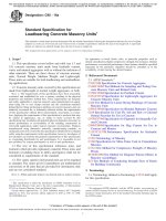
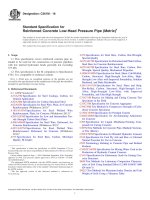
NOTE 1—The total reinforcement area of the inner circular cage and the elliptical cage shall not be less than that specified for the inner cage in Tables
1-5.
NOTE 2—The total reinforcement area of the outer circular cage and the elliptical cage shall not be less than that specified for the outer cage in Tables
1-5.
FIG. 1 Triple Cage Reinforcement
5. Basis of Acceptance
6. Materials
5.1 Unless otherwise designated by the owner at the time of,
or before placing an order, there are two separate and alternative bases of acceptance. Independent of the method of
acceptance, the pipe shall be designed to meet both the 0.01-in.
crack and ultimate strength requirements specified in Tables
1-5.
5.1.1 Acceptance on the Basis of Plant Load-Bearing Tests,
Material Tests, and Inspection of Manufactured Pipe for Visual
Defects and Imperfections—Acceptability of the pipe in all
diameters and classes produced in accordance with 7.1 or 7.2
shall be determined by the results of the three-edge bearing
tests as defined in 11.3.1; by such material tests as are required
in 6.2, 6.3, 6.5 and 6.6; by an absorption test of the concrete
from the wall of the pipe as required in 11.9; and by visual
inspection of the finished pipe to determine its conformance
with the accepted design and its freedom from defects.
5.1.2 Acceptance on the Basis of Material Test and Inspection of Manufactured Pipe for Defects and Imperfections—
Acceptability of the pipe in all diameters and classes produced
in accordance with 7.1 or 7.2 shall be determined by the results
of such material tests as are required in 6.2, 6.3, 6.5 and 6.6; by
crushing tests on concrete cores or cured concrete cylinders; by
an absorption test of the concrete from the wall of the pipe for
each mix design that is used on an order; and by inspection of
the finished pipe including amount and placement of reinforcement to determine its conformance with the accepted design
and its freedom from defects.
5.1.3 When agreed upon between the owner and
manufacturer, any portion or any combination of the tests
itemized in 5.1.1 or 5.1.2 may form the basis of acceptance.
6.1 Reinforced Concrete—The reinforced concrete shall
consist of cementitious materials, mineral aggregates, water,
and admixtures, if any, in which steel has been embedded in
such a manner that the steel and concrete act together.
6.2 Cementitious Materials:
6.2.1 Cement—Cement shall conform to the requirements
for portland cement of Specification C150/C150M or shall be
portland blast-furnace slag cement, portland-limestone cement,
or portland-pozzolan cement conforming to the requirements
of Specification C595/C595M, except that the pozzolan constituent in the Type IP portland-pozzolan cement shall be fly
ash.
6.2.2 Slag Cement—Slag cement shall conform to the requirements of Grade 100 or 120 of Specification C989/C989M.
6.2.3 Fly Ash—Fly ash shall conform to the requirements of
Class F or Class C of Specification C618.
6.2.4 Allowable Combinations of Cementitious Materials—
The combination of cementitious materials used in the concrete
shall be one of the following:
6.2.4.1 Portland cement only,
6.2.4.2 Portland blast-furnace slag cement only,
6.2.4.3 Portland-pozzolan cement only,
6.2.4.4 Portland-limestone cement only,
6.2.4.5 A combination of portland cement or portlandlimestone cement and slag cement,
6.2.4.6 A combination of portland cement or portlandlimestone cement and fly ash,
6.2.4.7 A combination of portland cement or portlandlimestone cement, slag cement, and fly ash, or
6.2.4.8 A combination of portland-pozzolan cement and fly
ash.
5.2 Age for Acceptance—Pipe shall be considered ready for
acceptance when it conforms to the requirements as indicated
by the specified tests.
2
C76M − 16
TABLE 1 Design Requirements for Class I Reinforced Concrete PipeA
NOTE 1—See Section 5 for basis of acceptance specified by owner.
The strength test requirements in newtons per linear metre of pipe under the three-edge-bearing method shall be either the D-load (test load expressed
in newtons per linear metre per millimetre of diameter) to produce the 0.3-mm crack, or the D-loads to produce the 0.3-mm crack and the ultimate load
as specified below, multiplied by the internal diameter of the pipe in millimetres.
D-load to produce a 0.3 mm crack
D-load to produce the ultimate load
40.0
60.0
Reinforcement, cm2/linear m of pipe wall
Internal
Designated
Diameter,
mm
Wall
Thickness,
mm
1500
1650
1800
1950
2100
2250
2400
125
138
150
163
175
188
200
2550
213
2700
225
2850
3000
3150
3300
3450
3600
A
A
A
A
A
A
Wall A
Wall B
Concrete Strength, 27.6 MPa
Concrete Strength, 27.6 MPa
Circular
ReinforcementB
Inner
Cage
Outer
Cage
5.3
6.4
7.4
8.5
9.5
10.4
11.4
3.2
3.8
4.4
5.1
5.7
6.2
6.8
Elliptical
ReinforcementC
Wall
Thickness,
mm
5.9
7.0
8.3
9.3
10.6
11.4
12.7
Concrete Strength, 34.5 MPa
Inner Circular
8.0
Plus Elliptical
Inner Circular
14.4
8.6
Plus Elliptical
...
...
...
...
...
...
...
...
...
...
...
...
...
...
...
...
...
...
13.3
5.3
8.0
5.8
8.6
...
...
...
...
...
...
Circular
ReinforcementB
Inner
Cage
Outer
Cage
150
163
175
188
200
213
225
4.4
5.3
6.1
6.8
7.8
8.7
9.7
2.6
3.2
3.7
4.1
4.7
5.2
5.8
238
11.4
6.8
250
12.9
7.7
A
...
...
...
...
...
...
...
...
...
...
...
...
A
A
A
A
A
Elliptical
ReinforcementC
4.9
5.9
6.8
7.6
8.7
9.7
10.8
Inner Circular
Plus Elliptical
Inner Circular
Plus Elliptical
...
...
...
...
...
...
4.6
6.8
5.2
7.7
...
...
...
...
...
...
A
For modified or special designs, see 7.2 or with the permission of the owner utilize the provisions of Specification C655M. Steel areas may be interpolated between
those shown for variations in diameter, loading, or wall thickness. Pipe over 2400 mm in diameter shall have two circular cages or an inner circular plus one elliptical cage.
B
As an alternative to designs requiring both inner and outer circular cages the reinforcement may be positioned and proportioned in either of the following manners:
An inner circular cage plus an elliptical cage such that the area of the elliptical cage shall not be less than that specified for the outer cage in the table and the total area
of the inner circular cage plus the elliptical cage shall not be less than that specified for the inner cage in the table,
An inner and outer cage plus quadrant mats in accordance with Fig. 2, or
An inner and outer cage plus an elliptical cage in accordance with Fig. 1.
C
Elliptical and quadrant steel must be held in place by means of holding rods, chairs, or other positive means throughout the entire casting operation.
6.3 Aggregates—Aggregates shall conform to Specification
C33/C33M except that the requirement for gradation shall not
apply.
and manufactured specifically for use in concrete and conforming to the requirements of Specification C1116/C1116M shall
be accepted.
6.4 Admixtures—The following admixtures and blends are
allowable:
6.4.1 Air-entraining admixture conforming to Specification
C260/C260M;
6.4.2 Chemical admixture conforming to Specification
C494/C494M;
6.4.3 Chemical admixture for use in producing flowing
concrete conforming to Specification C1017/C1017M; and
6.4.4 Chemical admixture or blend approved by the owner.
6.7 Water—Water used in the production of concrete shall
be potable or nonpotable water that meets the requirements of
Specification C1602/C1602M.
7. Design
7.1 Design Tables—The diameter, wall thickness, compressive strength of the concrete, and the area of the circumferential reinforcement shall be as prescribed for Classes I to V in
Tables 1-5, except as provided in 7.2.
7.1.1 The reinforcement as presented in the tables herein
allows single circular cage reinforcement or separate inner and
outer circular cage reinforcement or single elliptical cage
reinforcement or a combination thereof.
Footnotes to the tables are intended to clarify tabulated
requirements or provide acceptable alternative reinforcement
designs, either of which are applicable and binding as if they
were contained in the body of the specification.
6.5 Steel Reinforcement—Reinforcement shall consist of
wire and welded wire conforming to Specification A1064/
A1064M, or of bars conforming to Specification A36/A36M,
Specification A615/A615M Grade 280 or 420, or Specification
A706/A706M Grade 420. For helically wound cages only,
weld shear tests are not required.
6.6 Fibers—Synthetic fibers and nonsynthetic fibers shall be
allowed to be used, at the manufacturer’s option, in concrete
pipe as a nonstructural manufacturing material. Synthetic fibers
(Type II and Type III) and nonsynthetic fiber (Type I) designed
7.2 Modified and Special Designs:
3
C76M − 16
TABLE 2 Design Requirements for Class II Reinforced Concrete PipeA
NOTE 1—See Section 5 for basis of acceptance specified by owner.
The strength test requirements in newtons per linear metre of pipe under the three-edge-bearing method shall be either the D-load (test-load expressed
in newtons per linear metre per millimetre of diameter) to produce the 0.3-mm crack, or the D-loads to produce the 0.3-mm crack and the ultimate load
as specified below, multiplied by the internal diameter of the pipe in millimetres.
D-load to produce a 0.3 mm crack
D-load to produce the ultimate load
50.0
75.0
Reinforcement, cm2/linear m of pipe wall
Internal
Designated
Diameter,
mm
Wall A
Wall B
Wall C
Concrete Strength, 27.6 MPa
Concrete Strength, 27.6 MPa
Concrete Strength, 27.6 MPa
Circular
Wall
ReinforcementB
Thickness,
Inner
Outer
mm
Cage
Cage
Wall
Elliptical
Thickness,
ReinforcementC
mm
300
375
450
525
600
675
750
825
900
1050
1200
1350
1500
1650
1800
1950
2100
2250
2400
44
47
50
57
63
66
69
72
75
88
100
113
125
138
150
163
175
188
200
1.5D
1.5D
1.5D
2.5
2.8
3.2
3.2
3.4
3.0
3.4
4.5
5.3
6.4
7.4
8.7
9.7
10.8
12.1
13.1
...
...
...
...
...
...
...
...
1.8
2.0
2.7
3.2
3.8
4.4
5.2
5.8
6.5
7.3
7.9
...
...
1.5
2.1
2.3
2.8
3.0
3.2
3.2
3.8
4.9
5.9
7.0
8.3
9.5
10.8
12.1
13.3
14.6
2550
213
16.1
9.7
2700
225
18.0
10.8
2850
3000
3150
3300
3450
3600
A
Inner Circular 6.4
Plus Elliptical 9.7
Inner Circular 7.2
Plus Elliptical 10.8
...
...
...
...
...
...
...
...
...
...
...
...
A
A
A
A
A
...
...
...
...
...
...
...
...
...
...
...
...
Circular
ReinforcementB
Inner
Cage
Outer
Cage
Elliptical
ReinforcementC
50
1.5D
...
...
57
1.5D
...
...
63
1.5D
...
1.5D
D
69
1.5
...
1.5D
75
1.5D
...
1.5D
82
2.8
...
2.3
88
3.0
...
2.5
94
3.2
...
2.8
100E
2.5
1.5
2.8
113
3.2
1.9
3.6
125
3.8
2.3
4.2
138
4.7
2.8
5.1
150
5.3
3.2
5.9
163
6.6
4.0
7.2
175
7.4
4.4
8.3
188
8.5
5.1
9.3
200
9.7
5.8
10.8
213
10.8
6.5
12.1
225
12.1
7.3
13.3
Concrete Strength, 34.5 MPa
238
14.4
8.6
Inner Circular
Plus Elliptical
250
16.1
9.7
Inner Circular
Plus Elliptical
A
...
...
...
A
...
...
...
A
...
...
...
A
...
...
...
A
...
...
...
A
...
...
...
5.8
8.6
6.4
9.7
...
...
...
...
...
...
Wall
Thickness,
mm
Circular
ReinforcementB
Elliptical
ReinforcementC
Inner
Cage
Outer
Cage
69
75
82
88
94
100
106
113
119E
132
144
157
169
182
194
207
219
232
244
1.5D
1.5D
1.5D
1.5D
1.5D
1.5D
1.5D
1.5D
1.5
2.1
3.0
3.6
4.7
5.3
6.4
7.4
8.7
10.2
11.6
...
...
...
...
...
...
...
...
1.5
1.5
1.8
2.2
2.8
3.2
3.8
4.4
5.2
6.1
7.0
...
...
1.5D
1.5D
1.5D
1.5D
1.5D
1.5D
1.7
2.3
3.2
4.0
5.1
5.9
7.0
8.3
9.7
11.2
12.9
257
13.1
7.9
269
14.8
8.9
A
...
...
...
...
...
...
...
...
...
...
...
...
Inner Circular
Plus Elliptical
Inner Circular
Plus Elliptical
...
...
...
...
...
...
A
A
A
A
A
5.2
7.9
5.9
8.9
...
...
...
...
...
...
A
For modified or special designs, see 7.2 or with the permission of the owner utilize the provisions of Specification C655M. Steel areas may be interpolated between those
shown for variations in diameter, loading, or wall thickness. Pipe over 2400 mm in diameter shall have two circular cages or an inner circular plus one elliptical cage.
B
As an alternative to designs requiring both inner and outer circular cages the reinforcement may be positioned and proportioned in either of the following manners:
An inner circular cage plus an elliptical cage such that the area of the elliptical cage shall not be less than that specified for the outer cage in the table and the total area
of the inner circular cage plus the elliptical cage shall not be less than that specified for the inner cage in the table,
An inner and outer cage plus quadrant mats in accordance with Fig. 2, or
An inner and outer cage plus an elliptical cage in accordance with Fig. 1.
C
Elliptical and quadrant steel must be held in place by means of holding rods, chairs, or other positive means throughout the entire casting operation.
D
For these classes and sizes, the minimum practical steel reinforcement is specified. The specified ultimate strength of non-reinforced pipe is greater than the minimum
specified strength for the equivalent diameters.
E
As an alternative, single cage reinforcement may be used. The reinforcement area in square centimetres per linear metre shall be 4.2 for wall B and 3.4 for wall C.
wall thickness, the concrete strength, and the area, type,
placement, number of layers, and strength of the steel reinforcement.
7.2.3 The manufacturer shall submit to the owner proof of
the adequacy of the proposed modified or special design. Such
proof may comprise the submission of certified three-edgebearing tests already made, which are acceptable to the owner
or, if such three-edge-bearing tests are not available or
acceptable, the manufacturer may be required to perform proof
tests on sizes and classes selected by the owner to demonstrate
the adequacy of the proposed design.
7.2.1 If permitted by the owner the manufacturer may
request approval by the owner of modified designs that differ
from the designs in; or special designs for sizes and loads
beyond those shown in Tables 1-5, 7.1, or special designs for
pipe sizes that do not have steel reinforcement areas shown in
Tables 1-5.
7.2.2 Such modified or special designs shall be based on
rational or empirical evaluations of the ultimate strength and
cracking behavior of the pipe and shall fully describe to the
owner any deviations from the requirements of 7.1. The
descriptions of modified or special designs shall include the
4
C76M − 16
TABLE 3 Design Requirements for Class III Reinforced Concrete PipeA
NOTE 1—See Section 5 for basis of acceptance specified by owner.
The strength test requirements in newtons per linear metre of pipe under the three-edge-bearing method shall be either the D-load (test-load expressed
in newtons per linear metre per millimetre of diameter) to produce the 0.3-mm crack, or the D-loads to produce the 0.3-mm crack and the ultimate load
as specified below, multiplied by the internal diameter of the pipe in millimetres.
D-load to produce a 0.3 mm crack
D-load to produce the ultimate load
65.0
100.0
Reinforcement, cm2/linear m of pipe wall
Wall A
Internal
Concrete Strength, 27.6 MPa
Designated
Circular
Diameter,
Wall
ReinforcementB
Elliptical
mm
Thickness,
ReinforcementC
Inner
Outer
mm
Cage
Cage
...
...
1.5D
1.5D
...
...
...
1.5D
1.5D
3.0
...
2.3
3.6
...
3.0
3.8
...
3.4
4.0
...
3.8
4.4
...
4.2
4.4
2.6
4.7
5.3
3.2
5.9
6.8
4.1
7.4
8.0
4.8
8.9
9.3
5.6
10.4
10.6
6.4
11.6
12.1
7.3
13.3
Concrete Strength, 34.5 MPa
13.5
8.1
15.0
15.2
9.1
16.9
300
375
450
525
600
675
750
825
900
1050
1200
1350
1500
1650
1800
44
47
50
57
63
66
69
72
75
88
100
113
125
138
150
1950
2100
163
175
2250
2400
188
200
17.1
19.7
10.3
11.8
2550
213
21.8
13.1
2700
225
25.8
15.5
2850
3000
3150
3300
3450
3600
A
A
A
A
A
A
...
...
...
...
...
...
...
...
...
...
...
...
50
57
63
69
75
82
88
94
100E
113
125
138
150
163
175
188
200
19.1
21.8
Inner Circular
Plus Elliptical
Inner Circular
Plus Elliptical
...
...
...
...
...
...
Wall
Thickness,
mm
213
225
8.7
13.1
10.3
15.5
...
...
...
...
...
...
Wall B
Wall C
Concrete Strength, 27.6 MPa
Concrete Strength, 27.6 MPa
Circular
ReinforcementB
Inner
Cage
Outer
Cage
1.5D
1.5D
1.5D
1.5D
1.5D
3.4
3.8
4.2
3.6
4.4
5.1
6.1
7.2
9.1
10.4
...
...
...
...
...
...
...
2.2
2.6
3.1
3.7
4.3
5.5
6.2
D
19.1
11.5
250
22.9
13.7
A
...
...
...
...
...
...
...
...
...
...
...
...
A
A
A
A
...
...
1.5D
1.5D
1.5D
3.0
3.2
3.6
4.0
4.9
5.7
6.8
8.0
9.7
11.4
Inner Circular
Plus Elliptical
Inner Circular
Plus Elliptical
...
...
...
...
...
...
Circular
Wall
ReinforcementB
Thickness,
Inner
Outer
mm
Cage
Cage
69
75
82
88
94
100
107
113
119E
132
144
157
169
182
194
12.1
7.3
13.3
13.5
8.1
15.0
Concrete Strength, 34.5 MPa
14.6
8.8
16.3
16.1
9.7
17.8
238
A
Elliptical
ReinforcementC
207
219
232
244
7.6
11.5
9.2
13.7
...
...
...
...
...
...
257
269
A
A
A
A
A
A
1.5D
1.5D
1.5D
1.5D
1.5D
1.7
2.1
2.5
1.7
2.5
3.4
4.4
5.3
6.6
7.6
...
...
...
...
...
...
...
...
1.5
1.5
2.0
2.6
3.2
4.0
4.6
Elliptical
ReinforcementC
...
...
1.5D
1.5D
1.5D
1.5D
1.7
2.1
1.9
2.8
3.8
4.9
5.9
7.2
8.5
8.9
5.3
9.9
10.6
6.4
11.9
Concrete Strength, 34.5 MPa
12.5
7.5
14.0
14.8
8.9 Inner Circular
Plus Elliptical
17.6
10.6 Inner Circular
Plus Elliptical
21.0
12.6 Inner Circular
Plus Elliptical
...
...
...
...
...
...
...
...
...
...
...
...
...
...
...
...
...
...
5.9
8.9
7.0
10.6
8.4
12.6
...
...
...
...
...
...
A
For modified or special designs, see 7.2 or with the permission of the owner utilize the provisions of Specification C655M. Steel areas may be interpolated between
those shown for variations in diameter, loading, or wall thickness. Pipe over 2400 mm in diameter shall have two circular cages or an inner circular plus one elliptical cage.
B
As an alternative to designs requiring both inner and outer circular cages the reinforcement may be positioned and proportioned in either of the following manners:
An inner circular cage plus an elliptical cage such that the area of the elliptical cage shall not be less than that specified for the outer cage in the table and the total area
of the inner circular cage plus the elliptical cage shall not be less than that specified for the inner cage in the table,
An inner and outer cage plus quadrant mats in accordance with Fig. 2, or
An inner and outer cage plus an elliptical cage in accordance with Fig. 1.
C
Elliptical and quadrant steel must be held in place by means of holding rods, chairs, or other positive means throughout the entire casting operation.
D
For these classes and sizes, the minimum practical steel reinforcement is specified. The specified ultimate strength of non-reinforced pipe is greater than the minimum
specified strength for the equivalent diameters.
E
As an alternative, single cage reinforcement may be used. The reinforcement area in square centimetres per linear metre shall be 6.4 for wall B and 4.2 for wall C.
7.2.4 Such pipe must meet all of the test and performance
requirements specified by the owner in accordance with
Section 5.
two layers for pipe with wall thicknesses of less than 180 mm
or three layers for pipe with wall thicknesses of 180 mm or
greater. The layers shall not be separated by more than the
thickness of one longitudinal plus 6 mm. The multiple layers
shall be fastened together to form a single cage. All other
specification requirements such as laps, welds, and tolerances
of placement in the wall of the pipe, etc., shall apply to this
method of fabricating a line of reinforcement.
8.1.1 Where one line of circular reinforcement is used, it
shall be placed from 35 to 50 % of the wall thickness from the
inner surface of the pipe, except that for wall thicknesses less
7.3 Area—In this specification, when the word area is not
described by adjectives, such as cross-section or single wire, it
shall be understood to be the cross-sectional area of reinforcement per unit lengths of pipe.
8. Reinforcement
8.1 Circumferential Reinforcement—A line of circumferential reinforcement for any given total area may be composed of
5
C76M − 16
TABLE 4 Design Requirements for Class IV Reinforced Concrete PipeA
NOTE 1—See Section 5 for basis of acceptance specified by owner.
The strength test requirements in newtons per linear metre of pipe under the three-edge-bearing method shall be either the D-load (test load expressed
in newtons per linear metre per millimetre of diameter) to produce the 0.3-mm crack, or the D-loads to produce the 0.3-mm crack and the ultimate load
as specified below, multiplied by the internal diameter of the pipe in millimetres.
D-load to produce a 0.3 mm crack
D-load to produce the ultimate load
100.0
150.0
Reinforcement, cm2/linear m of pipe wall
Internal
Designated
Diameter,
mm
Wall A
Wall B
Wall C
Concrete Strength, 34.5 MPa
Concrete Strength, 27.6 MPa
Concrete Strength, 27.6 MPa
Wall
Thickness,
mm
300
375
450
525
600
675
750
825
900
1050
1200
1350
44
47
50
57
63
66
69
1500
1650
A
1800
1950
2100
2250
2400
A
2550
2700
2850
3000
3150
3300
3450
3600
A
A
A
A
A
A
A
A
A
A
A
A
A
A
A
A
A
Circular
ReinforcementB
Elliptical
ReinforcementC
Wall
Thickness,
mm
Inner
Cage
Outer
Cage
3.2
3.4
3.6
4.9
6.1
7.0
8.0
...
...
...
...
...
...
...
...
...
...
...
...
...
...
...
...
...
...
...
3.2
4.4
5.7
6.6
7.4
...
...
...
...
...
50
57
63
69
75
82
88
94
100
113
125
138
...
...
...
...
...
...
150
163
...
...
...
...
...
...
...
...
...
...
...
...
...
...
...
175
...
...
...
...
...
...
...
...
...
...
...
...
...
...
...
...
...
...
...
...
...
...
...
...
A
Circular
ReinforcementB
Inner
Cage
Outer
Cage
1.5
...
2.1
...
3.0
...
4.2
...
5.7
...
6.6
...
7.4
...
5.7
3.4
6.3
3.8
7.4
4.4
8.9
5.3
10.6
6.4
Concrete Strength, 34.5 MPa
12.5
7.5
14.6
8.8
16.7
...
...
...
...
...
...
...
...
...
...
...
...
...
A
A
A
A
A
A
A
A
A
A
A
10.0
...
...
...
...
...
...
...
...
...
...
...
...
...
Elliptical
ReinforcementC
Wall
Thickness,
mm
Circular
ReinforcementB
Inner
Cage
1.5D
1.5D
1.5D
1.5D
1.5
1.7
1.9
2.3
3.0
4.2
5.5
7.2
Outer
Cage
...
...
...
...
1.5
1.5
1.5
1.5
1.8
2.5
3.3
4.3
Elliptical
ReinforcementC
...
...
1.5D
1.5D
1.7
1.9
2.1
2.5
3.2
4.7
6.1
8.0
...
...
2.3
3.6
4.9
5.3
5.9
6.3
7.0
8.3
9.9
11.6
69
75
82
88
94
100
107
113
119
132
144
157
14.0
16.3
169
8.7
5.2
9.7
182
10.8
6.5
12.0
Concrete Strength, 34.5 MPa
194
12.9
7.7
14.4
207
15.0
9.0
16.7
219
18.0
10.8
19.9
A
...
...
...
A
...
...
...
A
...
...
...
A
...
...
...
A
...
...
...
A
...
...
...
A
...
...
...
A
...
...
...
A
...
...
...
A
...
...
...
...
...
...
...
18.6
...
...
...
...
...
...
...
...
...
...
...
...
...
A
For modified or special designs see 7.2 or with the permission of the owner utilize the provisions of Specification C655M. Steel areas may be interpolated between those
shown for variations in diameter, loading, or wall thickness. Pipe over 2400 mm in diameter shall have two circular cages or an inner circular plus one elliptical cage.
B
As an alternative to designs requiring both inner and outer circular cages the reinforcement may be positioned and proportioned in either of the following manners:
An inner circular cage plus an elliptical cage such that the area of the elliptical cage shall not be less than that specified for the outer cage in the table and the total area
of the inner circular cage plus the elliptical cage shall not be less than that specified for the inner cage in the table,
An inner and outer cage plus quadrant mats in accordance with Fig. 2, or
An inner and outer cage plus an elliptical cage in accordance with Fig. 1.
For Wall C, in sizes 600 to 825 mm, a single circular cage with an area not less than the sum of the specified inner and outer circular reinforcement areas.
C
Elliptical and quadrant steel must be held in place by means of holding rods, chairs, or other positive means throughout the entire casting operation.
D
For these classes and sizes, the minimum practical steel reinforcement is specified.
than 63 mm, the protective cover of the concrete over the
circumferential reinforcement in the wall of the pipe shall be
19 mm.
8.1.2 In pipe having two lines of circular reinforcement,
each line shall be so placed that the protective covering of
concrete over the circumferential reinforcement in the wall of
the pipe shall be 25 mm.
8.1.3 In pipe having elliptical reinforcement with wall
thicknesses 63 mm or greater, the reinforcement in the wall of
the pipe shall be so placed that the protective covering of
concrete over the circumferential reinforcement shall be 25
mm from the inner surface of the pipe at the vertical diameter
and 25 mm from the outer surface of the pipe at the horizontal
diameter. In pipe having elliptical reinforcement with wall
thicknesses less than 63 mm, the protective covering of the
concrete shall be 19 mm at the vertical and horizontal
diameters.
8.1.4 The location of the reinforcement shall be subject to
the permissible variations in dimensions given in 12.5.
8.1.5 The spacing center to center of circumferential reinforcement in a cage shall not exceed 100 mm for pipe up to and
including pipe having a 100 mm wall thickness nor exceed the
wall thickness for larger pipe, and shall in no case exceed 150
mm.
6
C76M − 16
TABLE 5 Design Requirements for Class V Reinforced Concrete PipeA
NOTE 1—See Section 5 for basis of acceptance specified by owner.
The strength test requirements in newtons per linear metre of pipe under the three-edge-bearing method shall be either the D-load (test load expressed
in newtons per linear metre per millimetre of diameter) to produce the 0.3-mm crack, or the D-loads to produce the 0.3-mm crack and the ultimate load
as specified below, multiplied by the internal diameter of the pipe in millimetres.
D-load to produce a 0.3 mm crack
D-load to produce the ultimate load
140.0
175.0
Reinforcement, cm2/linear m of pipe wall
Internal
Designated
Diameter,
mm
300
375
450
525
600
675
750
825
900
1050
1200
1350
1500
1650
1800
1950
2100
2250
2400
2550
2700
2850
3000
3150
3300
3450
3600
Wall
Thickness,
mm
A
A
A
A
A
A
A
A
A
A
A
A
A
A
A
A
A
A
A
A
A
A
A
A
A
A
A
Wall A
Wall B
Wall C
Concrete Strength, 41.4 MPa
Concrete Strength, 41.4 MPa
Concrete Strength, 41.4 MPa
Circular
ReinforcementB
Circular
ReinforcementB
Circular
ReinforcementB
Inner
Cage
Outer
Cage
...
...
...
...
...
...
...
...
...
...
...
...
...
...
...
...
...
...
...
...
...
...
...
...
...
...
...
...
...
...
...
...
...
...
...
...
...
...
...
...
...
...
...
...
...
...
...
...
...
...
...
...
...
...
Elliptical
ReinforcementC
Wall
Thickness,
mm
...
...
...
...
...
...
...
...
...
...
...
...
...
...
...
...
...
...
...
...
...
...
...
...
...
...
...
50
57
63
69
75
82
88
94
100
113
125
A
A
A
A
A
A
A
A
A
A
A
A
A
A
A
A
Inner
Cage
Outer
Cage
2.1
3.0
4.0
5.1
6.4
8.0
8.7
9.7
10.6
12.7
15.5
...
...
...
...
...
...
...
...
...
...
...
...
...
...
...
...
...
...
...
...
...
4.8
5.2
5.8
6.4
7.6
9.3
...
...
...
...
...
...
...
...
...
...
...
...
...
...
...
...
Elliptical
Wall
Reinforce- Thickness,
C
ment
mm
...
...
3.4
4.4
5.1
8.9
9.7
10.8
11.9
14.2
17.1
...
...
...
...
...
...
...
...
...
...
...
...
...
...
...
...
69
75
82
88
94
100
107
113
119
132
144
157
169
182
194
A
A
A
A
A
A
A
A
A
A
A
A
Inner
Cage
Outer
Cage
1.5D
1.5D
2.1
2.1
2.5
3.0
3.8
4.9
5.7
7.6
9.9
12.3
14.8
17.8
21.0
...
...
...
...
...
...
...
...
...
...
...
...
...
...
...
...
1.5
1.8
2.3
2.9
3.4
4.6
5.9
7.4
8.9
10.7
12.6
...
...
...
...
...
...
...
...
...
...
...
...
Elliptical
ReinforcementC
...
...
...
...
2.8
3.4
4.2
5.3
6.3
8.5
11.0
13.5
16.5
19.7
23.3
...
...
...
...
...
...
...
...
...
...
...
...
A
For modified or special designs see 7.2 or with the permission of the owner utilize the provisions of Specification C655M.
As an alternative to designs requiring both inner and outer circular cages the reinforcement may be positioned and proportioned in either of the following manners:
An inner circular cage plus an elliptical cage such that the area of the elliptical cage shall not be less than that specified for the outer cage in the table and the total area
of the inner circular cage plus the elliptical cage shall not be less than that specified for the inner cage in the table,
An inner and outer cage plus quadrant mats in accordance with Fig. 2, or
An inner and outer cage plus an elliptical cage in accordance with Fig. 1.
C
Elliptical and quadrant steel must be held in place by means of holding rods, chairs, or other positive means throughout the entire casting operation.
D
For these classes and sizes, the minimum practical steel reinforcement is specified.
B
8.1.6 Where the wall reinforcement does not extend into the
joint, the maximum longitudinal distance to the last circumferential from the inside shoulder of the bell or the shoulder of the
spigot shall be 75 mm, except that if this distance exceeds
one-half the wall thickness, the pipe wall shall contain at least
a total reinforcement area of the minimum specified area per
linear metre times the laying length of the pipe section. The
minimum cover on the last circumferential near the spigot
shoulder shall be 13 mm.
8.1.6.1 Where reinforcement is in the bell or spigot the
minimum and cover on the last circumferential shall be 13 mm
in the bell or 6 mm the spigot.
8.1.7 The continuity of the circumferential reinforcing steel
shall not be destroyed during the manufacture of the pipe,
except that when agreed upon by the owner, lift eyes or holes
may be provided in each pipe for the purpose of handling.
8.1.8 If splices are not welded, the reinforcement shall be
lapped not less than 20 diameters for deformed bars and
deformed cold-worked wire, and 40 diameters for plain bars
and cold-drawn wire. In addition, where lapped cages of
welded-wire fabric are used without welding, the lap shall
contain a longitudinal wire.
8.1.8.1 When splices are welded and are not lapped to the
minimum requirements above, there shall be a minimum lap of
50 mm and a weld such that pull tests of representative
specimens shall develop at least 50 % of the minimum specified tensile strength of the steel. For butt-welded splices in bars
or wire, permitted only with helically wound cages, pull tests
of representative specimens shall develop at least 75 % of the
minimum specified tensile strength of the steel. Pull tests shall
conform to Test Methods C497M.
7
C76M − 16
8.3.1.1 For pipe 900 mm and larger in diameter, either the
bell or spigot shall contain circumferential reinforcement. This
reinforcement shall be an extension of a wall cage, or may be
a separate cage of at least the area per metre of that specified
for the outer cage or one-half of that specified for single cage
wall reinforcement, whichever is less.
8.3.1.2 Where bells or spigots require reinforcement, the
maximum end cover on the last circumferential shall be
one-half the length of the joint or 75 mm, whichever is less.
8.3.2 Joint Reinforcement for Rubber Gasket Joints:
8.3.2.1 For pipe 300 mm and larger in diameter, the bell
ends shall contain circumferential reinforcement. This reinforcement shall be an extension of the outer cage or a single
wall cage, whichever is less, or may be a separate cage of at
least the same area per metre with longitudinals as required in
8.2. If a separate cage is used, the cage shall extend into the
pipe with the last circumferential wire at least 25 mm past the
inside shoulder where the pipe barrel meets the bell of the joint.
8.3.2.2 Where bells require reinforcement, the maximum
end cover on the last circumferential shall be 50 mm.
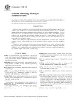
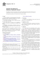
NOTE 1—The total reinforcement area (Asi) of the inner cage plus the
quadrant mat in Quadrants 1 and 2 shall not be less than that specified for
the inner cage in Tables 1-5.
NOTE 2—The total reinforcement area (Aso) of the outer cage plus the
quadrant mat in Quadrants 3 and 4 shall not be less than that specified for
the outer cage in Tables 1-5.
NOTE 3—The reinforcement area (A'si) of the inner cage in Quadrants
3 and 4 shall be not less than 25 % of that specified for the inner cage in
Tables 1-5.
NOTE 4—The reinforcement area (A'so) of the outer cage in Quadrants
1 and 2 shall be not less than 25 % of that specified for the outer cage in
Tables 1-5.
NOTE 5—If the reinforcement area (A'so) of the outer cage in Quadrants
1 or 2 is less than 50 % of that specified for the outer cage in Tables 1-5,
the quadrant mats used for the outer cage in Quadrants 3 and 4 shall
extend into Quadrants 1 and 2 not less than a distance equal to the wall
thickness as specified in Tables 1-5.
9. Joints
9.1 The joints shall be of such design and the ends of the
concrete pipe sections so formed that when the sections are laid
together they will make a continuous line of pipe with a smooth
interior free from appreciable irregularities in the flow line, all
compatible with the permissible variations given in Section 13.
9.2 Joints shall conform to the requirements of Specifications C443M, C990M, C1628, or other established joint types
approved by the owner, including, but not limited to, mortar,
sealant or externally-wrapped joints.
FIG. 2 Quadrant Reinforcement
8.1.8.2 When requested by the owner, the manufacturer
shall submit proof of the adequacy of the welded splices. Such
proof includes weld pull tests already made that are acceptable
to the owner or, if such tests are not available or acceptable,
pull tests on representative samples selected by the owner to
demonstrate the adequacy of the welded splice.
10. Manufacture
10.1 Mixture—The aggregates shall be sized, graded,
proportioned, and mixed with such proportions of cementitious
materials, water, and admixtures, if any, to produce a thoroughly mixed concrete of such quality that the pipe will
conform to the test and design requirements of this specification. All concrete shall have a water-cementitious materials
ratio not exceeding 0.53 by weight. Cementitious materials
shall be as specified in 6.2 and shall be added to the mix in a
proportion not less than 280 kg/m3 unless mix designs with a
lower cementitious materials content demonstrate that the
quality and performance of the pipe meet the requirements of
this specification.
10.1.1 Mixing Water—Water used in the production of
concrete shall be potable or nonpotable water that meets the
requirement of Specification C1602/C1602M.
8.2 Longitudinal Reinforcement—Each line of circumferential reinforcement shall be assembled into a cage that shall
contain sufficient longitudinal bars or members, to maintain the
reinforcement in shape and in position within the form to
comply with permissible variations in 8.1. The exposure of the
ends of longitudinals, stirrups, or spacers that have been used
to position the cages during the placement of the concrete shall
not be a cause for rejection.
8.3 Joint Reinforcement—The length of the joint as used
herein means the inside length of the bell or the outside length
of the spigot from the shoulder to the end of the pipe section.
The end distances or cover on the end circumferential shall
apply to any point on the circumference of the pipe or joint.
When convoluted reinforcement is used, these distances and
reinforcement areas shall be taken from the points on the
convolutions closest to the end of the pipe section. Unless
otherwise permitted by the owner, the following requirements
for joint reinforcement shall apply.
8.3.1 Joint Reinforcement for Non-Rubber Gasket Joints:
10.2 Curing—Pipe shall be subjected to any one of the
methods of curing described in 10.2.1 to 10.2.3 or to any other
method or combination of methods approved by the owner, that
will give satisfactory results. The pipe shall be cured for a
sufficient length of time so that the specified D-load is obtained
when acceptance is based on 5.1.1 or so that the concrete will
develop the specified compressive strength at 28 days or less
when acceptance is based on 5.1.2.
8
C76M − 16
11.3 External Load Crushing Strength:
11.3.1 The load to produce a 0.3-mm crack or the ultimate
load, as determined by the three-edge-bearing method as
described in the Test Methods C497M shall be not less than
that prescribed in Tables 1-5 for each respective class of pipe.
Pipe that support the prescribed load to produce the 0.3–mm
crack and do not show a wider crack shall be considered to
have met that test requirement. It is not a requirement of this
specification that the pipe be cracked or loaded to failure
during these tests. Pipe that have been tested only to the
formation of a 0.3-mm or lesser crack and that meet the
0.3-mm crack load requirements shall be accepted for use.
Three-edge bearing test to ultimate load is not required for any
class of pipe 1500 mm or less in diameter listed in Tables 1-5
provided all other requirements of this specification are met.
10.2.1 Steam Curing—Pipe shall be placed in a curing
chamber, free of outside drafts, and cured in a moist atmosphere maintained by the injection of live steam for such time
and such temperature as needed to enable the pipe to meet the
strength requirements. At no time shall the ambient temperature exceed 71°C. The curing chamber shall be so constructed
as to allow full circulation around the inside and outside of the
pipe.
10.2.2 Water Curing—Concrete pipe may be water-cured by
covering with water saturated material or by a system of
perforated pipes, mechanical sprinklers, porous hose, or by any
other approved method that will keep the pipe moist during the
specified curing period.
10.2.3 A sealing membrane conforming to the requirements
of Specification C309 may be applied and should be left intact
until the required strength requirements are met. The concrete
at the time of application shall be within 6°C of the atmospheric temperature. All surfaces shall be kept moist prior to
the application of the compounds and shall be damp when the
compound is applied.
10.2.4 The manufacturer may, at his option, combine the
methods described in 10.2.1 to 10.2.3 provided the required
concrete compressive strength is attained.
NOTE 3—As used in this specification, the 0.3-mm crack is a test
criterion for pipe tested in three-edge bearing-test and is not intended as
an indication of overstressed or failed pipe under installed conditions.
11.3.2 Retests of Pipe Not Meeting the External Load
Crushing Strength Requirements—Pipe shall be considered as
meeting the strength requirements when all test specimens
conform to the strength requirements. Should any of the test
specimens fail to meet the strength requirements, the manufacturer shall be allowed a retest on two additional specimens for
each specimen that failed, and the pipe shall be acceptable only
when all of the retest specimens meet the strength requirements.
CONCRETE TESTING
11. Physical Requirements
11.1 Test Specimens—The specified number of pipe required for the tests shall be furnished without charge by the
manufacturer and shall be selected at random by the owner, and
shall be pipe that would not otherwise be rejected under this
specification. The selection shall be made at the point or points
designated by the owner when placing the order.
11.4 Type of Specimen—Compression tests determining
concrete compressive strength may be made on either standard
rodded concrete cylinders or concrete cylinders compacted and
cured in like manner as the pipe, or on cores drilled from the
pipe.
11.2 Number and Type of Tests Required for Various Delivery Schedules:
11.2.1 Small Orders—Small orders are those that consist of
less than 100 pieces of each size and class of pipe. The owner
of such an order shall be entitled to copies of test reports as are
routinely performed on the particular lot, as required by the
type and basis of acceptance specified by the owner in Section
5. A lot shall include up to five consecutive days of production,
or 100 pieces, whichever is greater, provided the process and
mix design is not altered in any way between production days.
11.2.2 Large Orders—For orders of 100 or more pieces of a
size and class, the owner shall be entitled to tests per Section
5 on not more than one pipe per lot except where 11.2.3 and
11.2.4 are applicable.
11.2.3 Tests for Extended Delivery Schedules for Large
Orders—An owner of pipe, whose needs require shipments at
intervals over extended periods of time, shall be entitled to
such tests, preliminary to delivery of pipe, as are required by
the type of basis of acceptance specified by the owner in
Section 5, of not more than three sections of pipe covering each
size in which the owner is interested.
11.2.4 Additional Tests for Extended Delivery
Schedules—An owner shall be entitled to additional tests at
such times as the owner may deem necessary, provided that the
total number of pipe tested shall not exceed one pipe or 1 %,
whichever is the greater, of each size and class of the pipe in
the original order.
11.5 Compression Testing of Cylinders:
11.5.1 Cylinder Production—Cylinders shall be prepared in
accordance with Section 11 of Test Methods C497M.
11.5.2 Number of Cylinders—Prepare no fewer than five test
cylinders from a group (one day’s production) of pipe sections.
11.5.3 Acceptability on the Basis of Cylinder Test Results:
11.5.3.1 When the compressive strengths of all cylinders
tested for a group are equal to or greater than the required
concrete strength, the compressive strength of concrete in the
group of pipe sections shall be accepted.
11.5.3.2 When the average compressive strength of all
cylinders tested is equal to or greater than the required concrete
strength, and not more than 10 % of the cylinders tested have
a compressive strength less than the required concrete strength,
and no cylinder tested has a compressive strength less than
80 % of the required concrete strength, then the group shall be
accepted.
11.5.3.3 When the compressive strength of the cylinders
tested does not conform to the acceptance criteria stated in
11.5.3.1 or 11.5.3.2, the acceptability of the group shall be
determined in accordance with the provisions of 11.6.
11.6 Compression Testing of Cores:
11.6.1 Obtaining Cores—Cores shall be obtained and prepared in accordance with Section 6 of Test Methods C497M.
9
C76M − 16
11.11 Test Equipment—Every manufacturer furnishing pipe
under this specification shall furnish all facilities and personnel
necessary to carry out the tests described in Test Methods
C497M.
11.6.2 Number of Cores—One core shall be taken from a
pipe section selected at random from each day’s production run
of a single concrete strength.
11.7 Acceptability on the Basis of Core Test Results:
11.7.1 When the compressive strengths of cores tested for a
group of pipe sections is equal to or greater than the required
concrete strength, the compressive strength of the concrete for
the group is acceptable. Concrete represented by core tests
shall be considered acceptable if: (1) the average of three cores
is equal to at least 85 % of the required strength, and (2) no
single core is less than 75 % of the required strength.
11.7.2 If the compressive strength of the core tested is less
than the required concrete strength, the pipe section from
which that core was taken may be recored. If the compressive
strength of the recore is equal to or greater than the required
concrete compressive strength, the compressive strength of the
concrete for the group is acceptable.
11.7.3 If the compressive strength of the recore is less than
the required concrete strength, the pipe section from which the
core was taken shall be rejected. Two pipe sections from the
remainder of the group shall be selected at random and one
core shall be taken from each pipe section. If the compressive
strength of both cores is equal to or greater than the required
concrete compressive strength, the concrete compressive
strength of the remainder of the group shall be acceptable. If
the compressive strength of either of the two cores tested is less
than the required concrete compressive strength, then the
remainder of the group shall be either rejected or, at the option
of the manufacturer, each pipe section of the remainder shall be
cored and accepted individually, and any of the pipe sections
that have a core with less than the required concrete compressive strength shall be rejected.
12. Permissible Variations
12.1 Internal Diameter—See Table 6. At the manufacturer’s
option, the internal diameter shall be one of two alternatives,
the Designated Diameter or the Converted English Diameter.
Pipe sections that are intended to be jointed to each other shall
be furnished with the same internal diameter alternative. The
internal diameter of pipe manufactured to the Designated
Diameters shall vary not more than 61.5% from the Designated Diameter for 300 mm to 600 mm and 61 % or 610 mm,
whichever is greater, for larger pipe. The internal diameter of
pipe manufactured to the Converted English Diameters shall
vary not more than 61.5 % from the Converted English
Diameter for 305 mm to 610 mm and 61 % or 610 mm,
whichever is greater, for larger pipe. For pipe manufactured to
converted English Diameters, the corresponding Designated
Diameter shown in Table 6 shall apply for all other requirements of this specification.
12.2 Wall Thickness—The wall thickness shall not vary
more than shown in the design or specified wall by more than
65 % or 5 mm, whichever is greater. A specified wall thickness
more than required in the design is not cause for rejection. Pipe
having localized variations in wall thickness exceeding those
specified above shall be accepted if the three-edge-bearing
strength and minimum steel cover requirements are met.
12.3 Length of Two Opposite Sides—Variations in the laying
length of two opposite sides of the pipe shall not be more than
6 mm for all sizes through 600-mm internal diameter, and not
more than 10 mm/m of internal diameter for all sizes larger
11.8 Plugging Core Holes—Core holes shall be plugged and
sealed by the manufacturer in a manner such that the pipe
section will meet all of the requirements of this specification.
Pipe sections so plugged and sealed shall be considered
satisfactory for use.
TABLE 6 Design Internal Diameters
11.9 Absorption—An annual absorption test shall be performed for each mix design for each production process. The
absorption of a sample from the wall of the pipe, as determined
in accordance with Test Methods C497M, shall not exceed 9 %
of the dry mass for Method A or 8.5 % for Method B. Each
Method A sample shall have a minimum mass of 1.0 kg, shall
be free of visible cracks, and shall represent the full wall
thickness of the pipe. When the initial absorption sample from
a pipe fails to conform to this specification, the absorption test
shall be made on another sample from the same pipe and the
results of the retest shall be substituted for the original test
results.
11.10 Retests of Pipe—When not more than 20 % of the
concrete specimens fail to pass the requirements of this
specification, the manufacturer may cull the project stock and
may eliminate whatever quantity of pipe desired and shall mark
those pipe so that they will not be shipped. The required tests
shall be made on the balance of the order and the pipe shall be
accepted if they conform to the requirements of this specification.
10
Designated Diameter of
Pipe, mm
Equivalent English
Diameter, in.
Converted English Diameter,
mm
300
375
450
525
600
675
750
825
900
1050
1200
1350
1500
1650
1800
1950
2100
2250
2400
2550
2700
2850
3000
3150
3300
3450
3600
12
15
18
21
24
27
30
33
36
42
48
54
60
66
72
78
84
90
96
102
108
114
120
126
132
138
144
305
381
457
533
610
686
762
838
914
1067
1219
1372
1524
1676
1829
1981
2134
2286
2438
2591
2743
2896
3048
3200
3353
3505
3658
C76M − 16
14. Inspection
with a maximum of 16 mm in any length of pipe through
2100-mm internal diameter, and a maximum of 19 mm for
2250-mm internal diameter or larger, except where beveled end
pipe for laying on curves is specified by the owner.
14.1 The quality of materials, the process of manufacture,
and the finished pipe shall be subject to inspection and
approval by the owner.
12.4 Length of Pipe—The underrun in length of a section of
pipe shall not be more than 10 mm/m with a maximum of 13
mm in any length of pipe. Regardless of the underrun or
overrun in any section of pipe, the end cover requirements of
Section 8 and Section 12 shall apply.
15. Rejection
15.1 Pipe shall be subject to rejection on account of failure
to conform to any of the specification requirements. Individual
sections of pipe may be rejected because of any of the
following:
15.1.1 Fractures or cracks passing through the wall, except
for a single end crack that does not exceed the depth of the
joint.
15.1.2 Defects that indicate proportioning, mixing, and
molding not in compliance with 10.1 or surface defects
indicating honeycombed or open texture that would adversely
affect the function of the pipe.
15.1.3 The ends of the pipe are not normal to the walls and
center line of the pipe, within the limits of variations given in
12.3 and 12.4.
15.1.4 Damaged or cracked ends where such damage would
prevent making a satisfactory joint.
15.1.5 Any continuous crack having a surface width of 0.3
mm or more and extending for a length of 300 mm or more,
regardless of position in the wall of the pipe, for pipe not
installed or under load.
12.5 Position or Area of Reinforcement:
12.5.1 Position—The maximum variation in the position of
a line of circumferential reinforcement shall be 610 % of the
wall thickness or 613 mm, whichever is greater. Pipes having
variations in the position of a line of circumferential reinforcement exceeding those specified above shall be accepted if the
three-edge-bearing strength requirements obtained on a representative specimen are met. In no case, however, shall the
cover over the circumferential reinforcement be less than 6 mm
as measured to the end of the spigot or 13 mm as measured to
any other surface. The preceding minimum cover limitations
do not apply to mating surfaces of non-rubber gasket joints or
gasket grooves in rubber gasket joints. If convoluted reinforcement is used, the convoluted circumferential end wire may be
at the end surface of the joint providing the alternate convolutions have at least 25 mm cover from the end surface of the
joint.
12.5.2 Area of Reinforcement—Reinforcement will be considered as meeting the design requirements if the area, computed on the basis of nominal area of the wire or bars used,
equals or exceeds the requirements of 7.1 or 7.2. Actual area of
the reinforcing used may vary from the nominal area according
to permissible variations of the standard specifications for the
reinforcing. When inner cage and outer cage reinforcing is
used, the inner cage nominal area may vary to the lower limit
of 85 % of the elliptical nominal area and the outer cage
nominal area may vary to the lower limit of 51 % of the
elliptical nominal area provided that the total nominal area of
the inner cage plus the outer cage shall not vary beyond the
lower limit of 140 % of the elliptical nominal area.
16. Product Marking
16.1 The following information shall be legibly marked on
each section of pipe:
16.1.1 The pipe class and specification designation.
16.1.2 The date of manufacture.
16.1.3 The name or trademark of the manufacturer, and
16.1.4 Identification of plant.
16.2 One end of each section of pipe with elliptical or
quadrant reinforcement shall be clearly marked during the
process of manufacturing or immediately thereafter, on the
inside and the outside of opposite walls along the minor axis of
the elliptical reinforcing or along the vertical axis for quadrant
reinforcing.
16.3 Markings shall be indented on the pipe section or
painted thereon with waterproof paint.
13. Repairs
13.1 Pipe may be repaired, if necessary, because of imperfections in manufacture or damage during handling and will be
acceptable if, in the opinion of the owner, the repaired pipe
conforms to the requirements of this specification.
17. Keywords
17.1 circular pipe; culvert; D-load; pipe; reinforced concrete; sewer pipe; storm drain
11
C76M − 16
ASTM International takes no position respecting the validity of any patent rights asserted in connection with any item mentioned
in this standard. Users of this standard are expressly advised that determination of the validity of any such patent rights, and the risk
of infringement of such rights, are entirely their own responsibility.
This standard is subject to revision at any time by the responsible technical committee and must be reviewed every five years and
if not revised, either reapproved or withdrawn. Your comments are invited either for revision of this standard or for additional standards
and should be addressed to ASTM International Headquarters. Your comments will receive careful consideration at a meeting of the
responsible technical committee, which you may attend. If you feel that your comments have not received a fair hearing you should
make your views known to the ASTM Committee on Standards, at the address shown below.
This standard is copyrighted by ASTM International, 100 Barr Harbor Drive, PO Box C700, West Conshohocken, PA 19428-2959,
United States. Individual reprints (single or multiple copies) of this standard may be obtained by contacting ASTM at the above
address or at 610-832-9585 (phone), 610-832-9555 (fax), or (e-mail); or through the ASTM website
(www.astm.org). Permission rights to photocopy the standard may also be secured from the Copyright Clearance Center, 222
Rosewood Drive, Danvers, MA 01923, Tel: (978) 646-2600; />
12