Astm b 196 b 196m 07 (2013)e1
Bạn đang xem bản rút gọn của tài liệu. Xem và tải ngay bản đầy đủ của tài liệu tại đây (99.66 KB, 5 trang )
Designation: B196/B196M − 07 (Reapproved 2013)´1
Standard Specification for
Copper-Beryllium Alloy Rod and Bar1
This standard is issued under the fixed designation B196/B196M; the number immediately following the designation indicates the year
of original adoption or, in the case of revision, the year of last revision. A number in parentheses indicates the year of last reapproval.
A superscript epsilon (´) indicates an editorial change since the last revision or reapproval.
This standard has been approved for use by agencies of the U.S. Department of Defense.
ε1 NOTE—Corrections were made in Table 3 and 10.2.1 editorially in September 2015.
2.2 ASTM Standards:2
B194 Specification for Copper-Beryllium Alloy Plate, Sheet,
Strip, and Rolled Bar
B249/B249M Specification for General Requirements for
Wrought Copper and Copper-Alloy Rod, Bar, Shapes and
Forgings
B601 Classification for Temper Designations for Copper and
Copper Alloys—Wrought and Cast
B846 Terminology for Copper and Copper Alloys
E8 Test Methods for Tension Testing of Metallic Materials
E8M Test Methods for Tension Testing of Metallic Materials
[Metric] (Withdrawn 2008)3
1. Scope*
1.1 This specification establishes the requirements for
copper-beryllium alloy rod and bar in straight lengths. The
following three alloys are included:
Copper Alloy
UNS No.
C17000
C17200
C17300
Previously Used
Designations
Nominal Beryllium
Content, %
Alloy 165
Alloy 25
1.7
1.9
1.9
+0.4 lead
1.2 Unless otherwise required, Copper Alloy UNS No.
C17200 shall be the alloy furnished whenever Specification
B196/B196Mis specified without any alloy designation.
3. General Requirements
1.3 The values stated in either inch-pounds or SI units are to
be regarded separately as the standard. Within the text, the SI
units are shown in brackets. The values stated in each system
may not be exact equivalents; therefore, each system shall be
used independently of the other. Combining values from the
two systems may result in nonconformance with the specification.
1.4 This standard does not purport to address all of the
safety concerns, if any, associated with its use. It is the
responsibility of the user of this standard to establish appropriate safety and health practices and determine the applicability of regulatory limitations prior to use.
3.1 The following sections of Specification B249/B249M
constitute a part of this specification:
3.1.1 Terminology;
3.1.2 Dimensions and Permissible Variations;
3.1.3 Workmanship, Finish, and Appearance;
3.1.4 Sampling;
3.1.5 Number of Tests and Retests;
3.1.6 Specimen Preparation;
3.1.7 Test Methods;
3.1.8 Significance of Numerical Limits;
3.1.9 Inspection;
3.1.10 Rejection and Rehearing;
3.1.11 Certification;
3.1.12 Mill Test Report;
3.1.13 Packaging and Package Marking; and
3.1.14 Heat Identification
2. Referenced Documents
2.1 The following documents in the current issue of the
Book of Standards form a part of this specification to the extent
referenced herein:
1
This specification is under the jurisdiction of ASTM Committee B05 on Copper
and Copper Alloys and is the direct responsibility of Subcommittee B05.02 on Rod,
Bar, Wire, Shapes and Forgings.
Current edition approved April 1, 2013. Published April 2013. Originally
approved in 1945 to replace portions of B120 – 41 T. Last previous edition approved
in 2007 as B196/B196M-07. DOI: 10.1520/B0196_B0196M-07R13E01.
2
For referenced ASTM standards, visit the ASTM website, www.astm.org, or
contact ASTM Customer Service at For Annual Book of ASTM
Standards volume information, refer to the standard’s Document Summary page on
the ASTM website.
3
The last approved version of this historical standard is referenced on
www.astm.org.
*A Summary of Changes section appears at the end of this standard
Copyright © ASTM International, 100 Barr Harbor Drive, PO Box C700, West Conshohocken, PA 19428-2959. United States
1
B196/B196M − 07 (2013)´1
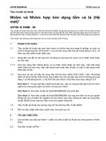
TABLE 1 Chemical Requirements
3.2 In addition, when a section with a title identical to that
referenced in 3.1 above appears in this specification, it contains
additional requirements which supplement those appearing in
Specification B249/B249M.
Composition,%
Element
Copper Alloy UNS No.
C17000
Beryllium
Nickel + cobalt, min
Nickel + cobalt
+ iron, max
Aluminum, max
Silicon, max
Lead
Copper
4. Terminology
4.1 For terms related to copper and copper alloys, refer to
Terminology B846.
4.2 Definitions of Terms Specific to This Standard:
4.2.1 Heat—A heat shall be the result of castings poured
simultaneously from the same source of molten metal.
4.2.2 Lot—The lot shall be a heat or fraction thereof.
5. Ordering Information
C17200
C17300
1.60–1.85
0.20
0.6
1.80–2.00
0.20
0.6
1.80–2.00
0.20
0.6
0.20
0.20
...
remainder
0.20
0.20
...
remainder
0.20
0.20
0.20–0.6
remainder
6.2.1 The product shall be produced with a combination hot
working, cold working, and thermal processing to produce a
uniform wrought structure and the specified temper.
5.1 Orders for products should include the following
information, as applicable:
5.1.1 ASTM specification designation and year of issue,
5.1.2 Quantity,
5.1.3 Copper Alloy UNS No. designation (Section 1),
5.1.4 Form of material (rod or bar and cross section, such as
round, hexagonal, and so forth),
5.1.5 Temper (Section 8),
5.1.6 Dimensions (diameter or distance between parallel
surfaces, and length),
5.1.7 How furnished (stock or specific lengths, with or
without ends), and
5.1.8 When material is ordered for agencies of the U.S.
government (See Section 11).
7. Chemical Composition
7.1 The material shall conform to the chemical composition
requirements prescribed in Table 1 for Copper Alloy UNS No.
designation specified in the ordering information.
7.2 These composition limits do not preclude the presence
of other elements. Limits for unnamed elements may be
established and analysis required by agreement between the
manufacturer, or supplier, and purchaser.
7.3 Copper is customarily given as remainder, but may be
taken as the difference between the sum of all elements
analyzed and 100 %.
5.2 The following options are available and should be
specified in the contract or purchase order when required:
5.2.1 Type of edge (square corners, rounded corners,
rounded edge, full-rounded edge),
5.2.2 Mechanical properties (tension test and hardness)
(Section 10),
5.2.3 Certification, and
5.2.4 Mill Test Report.
7.4 When all the elements in Table 1 are determined, the
sum of results shall be 99.5 % min.
8. Temper
8.1 The standard temper designations available under this
specification and as specified in Practice B601 are solution
heat-treated TB00 (A), and cold-drawn hard TD04 (H), (see
Table 2) to be precipitation heat treated by the user. Also
available are products already precipitation heat treated by the
manufacturer, tempers TF00 (AT) and TH04 (HT). These
products meet property requirements in Table 3 and normally
require no further heat treatment by the user.
6. Materials and Manufacture
6.1 Material:
6.1.1 The material of manufacture shall be Copper Alloy
UNS No. C17000, C17200, or C17300, cast and worked and of
such purity and soundness as to be suitable for processing into
the products prescribed herein.
6.1.2 Heat traceability shall be maintained and reported on
the Mill Test Report or Certification.
9. Precipitation Heat Treatment
9.1 The precipitation heat treatment is performed on TB00
(A) and TD04 (H) tempers by the purchaser, after machining or
forming.
6.2 Manufacture:
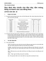
TABLE 2 Solution Heat-Treated and Solution Heat-Treated and Cold-Worked Mechanical Property Requirements
Temper Designation
A
Standard
Former
TB00
Solution heat treated (A)
TD04
Hard (H)
Diameter or Maximum
Distance Between
Parallel Surfaces
in.
mm
all sizes
all sizes
Tensile
Strength,
ksi
60–85
Tensile
Strength,
MPa
410–590
Yield Strength, min
0.2 % offset, ksi
20
up to 3⁄8, incl.
up to 10
over 3⁄8 to 1 incl. over 10 to 25 incl.
over 1 to 3, incl.
over 25 to 75
90–130
90–125
85–120
620–900
620–860
590–830
75
75
75
4 × D = 4 × diameter.
2
MPa
140
Rockwell
Hardness,
B Scale
45–85
Elongation in
4 × DA ,
min, %
20
520
520
520
88–103
88–102
88–101
8
8
8
3
up to 76.2
over 76.2
145
145
135
over 1 to 3, incl. over 25.4 to 76.2, incl. 165–200C 1140–1380C
Tensile
Tensile
Strength,
Strength
ksi
MPa
150–190C 1030–1310C
150–190C 1030–1310C
170–210C 1210–1450C
170–210C 1170–1450C
up to 10†
up to 3⁄8, incl.
over 3⁄8 to 1, incl. over 10† to 25.4, incl.
up to 3, incl.
over 3
Diameter or Maximum Distance
Between Parallel Surfaces
in.
mm
B
C17000
Yield Strength,
min, 0.2 %
offset, ksi
125
125
930
1000
1000
860
860
MPa
34–39
35–41
35–41
Rockwell
Hardness,
C Scale
32–39
32–39
175–215C
185–225C
180–220C
Tensile
Strength,
ksi
165–200C
165–200C
Copper Alloy UNS No.
1210–1480C
1280–1550C
1240–1520C
145
160
155
1000
1100
1070
C17200 and C17300
Yield Strength,
min, 0.2 %
MPa
MPa
offset, ksi
C
1140–1380
145
1000
1140–1380C
130
900
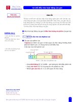
TABLE 3 Precipitation Heat-Treated Mechanical Property RequirementsA
These values apply to standard qualification heat treatment, see 8.1.
4 × D = 4 × diameter.
C
The upper limits in the tensile strength column are for design guidance only.
A
† Editorially corrected.
Hard (HT)
Solution heat
treated (AT)
TF00
TH04
Former
Standard
Temper Designation
37–44
39–45
38–44
Rockwell
Hardness, C
Scale
36–42
36–42
4
2
2
4
3
Elongation
in 4 × DB ,
min, %
B196/B196M − 07 (2013)´1
B196/B196M − 07 (2013)´1
conform to the special government requirements specified in
the Supplementary Requirements section of Specification
B249/B249M.
9.2 Conformance to the TF00 (AT) and TH04 (HT) specification limits shown in Table 3, for products supplied in the
TB00 (A) or the TD04 (H) tempers, shall be determined by
testing test specimens heat treated at a uniform temperature of
600 to 675°F (316 to 357°C) for the times shown in Table 4.
12. Dimensions and Permissible Variations
9.3 End products may be heat treated at other times and
temperatures for specific applications. These special combinations of properties such as increased ductility, electrical
conductivity, dimensional accuracy, endurance life, and resistance to elastic drift and hysteresis in springs, may be obtained
by special precipitation-hardening heat treatments. The mechanical requirements of Table 3 do not apply to such special
heat treatments. Specific test requirements as needed shall be
agreed upon between the manufacturer or supplier and purchaser of the end product.
12.1 The dimensions and tolerances for material covered by
this specification shall be as prescribed in the current edition of
Specification B249/B249M:
12.2 Diameter or Distance Between Parallel Surfaces:
12.2.1 Rod, Round, Hexagonal, Octagonal
12.2.2 Rod, Hot-Rolled, Round
12.2.3 Rod, As-Extruded
12.2.4 Bar, Rectangular and Square
12.2.5 Bar, As-Extruded
12.3 Length
9.4 TF00 (AT) and TH04 (HT) tempers as standard millhardened products have been precipitation heat treated and
tested by the manufacturer for conformance to the specification
limits shown in Table 3. Further thermal treatments of these
tempers are not normally required.
12.4 Straightness
12.5 Edge Contours
13. Workmanship, Finish, and Appearance
13.1 The product shall be free of defects, but blemishes of
a nature that do not interfere with the intended application are
acceptable.
10. Mechanical Property Requirements
10.1 Tensile Test Requirements:
10.1.1 The tension test, in accordance with Test Methods E8
or E8M, shall be the standard test for rod (round, hexagonal,
and octagonal) and bar (square) having a nominal diameter or
distance between parallel surfaces up to 3⁄8 in. [10 mm] incl,
and other shapes having a nominal cross-sectional area up to
0.141 in.2 [100 mm2], incl. The tensile strength requirements
shall be prescribed in Table 2 and Table 3 after precipitation
heat treatment in accordance with 8.1.
14. Sampling
14.1 Sampling shall be in accordance with Specification
B249/B249M, except that the heat size is defined as 12 000 lbs
(5455 kg) or fraction thereof.
14.2 Sample pieces shall be taken from a heat and lot of
material processed simultaneously in the same equipment, as
follows:
10.2 Rockwell Hardness Requirements:
10.2.1 Hardness shall be the standard test for round,
hexagonal, octagonal, and square rod larger than 3⁄8 in.
[10 mm] nominal diameter or distance between parallel surfaces and other shapes having a nominal cross-sectional area
exceeding 0.141 in.2 [3.6 mm]. The hardness requirements
shall be as prescribed in Table 2 for solution heat treated or
solution heat treated and cold worked and in Table 4 after
prescribed heat treatment. The tension test should not be made
except when indicated by the purchaser.
10.2.2 Where agreement on Rockwell hardness tests cannot
be reached, the tensile strength requirements of Tables 2 and 3
shall be the basis for acceptance or rejection.
15. Number of Tests and Retests
15.1 Section 9 of Specification B249/B249M constitutes a
part of this specification.
11. Purchases for U. S. Government
15.2 Test specimens shall be taken from the sample pieces
selected in accordance with 14.1.
15.2.1 In the case of product shipped in the TB00 or TD04
condition, two test specimens shall be taken from each sample
piece. One is to be tested in the as-sampled condition, and one
in the precipitation heat-treated condition.
15.2.2 In the case of product shipped in the precipitation
heat-treated condition, one specimen from each sample shall be
tested.
11.1 When specified in the contract or purchase order,
product purchased for an agency of the U. S. government shall
15.3 Retests—If any lot of material fails to conform to the
requirements of this specification as a result of inaccurate heat
TABLE 4 Standard Precipitation Heat Treatment Time for Acceptance Tests
Diameter or Distance Between
Parallel Surfaces, in.
Temper Designation
Standard
TB00
TD04
Former
Solution heat treated (A)
Hard (H)
Time at 600 to 675°F,
in.
mm
h
all sizes
up to 3⁄4, incl.
over 3⁄4
all sizes
up to 19.1, incl.
over 19.1
3
2
3
4
B196/B196M − 07 (2013)´1
treatment, new samples of material may be resubmitted for test
after proper heat treatment. Only two such reheat treatments
shall be permitted.
17. Test Methods
17.1 Section 11 of Specification B249/B249M constitutes a
part of this specification.
17.2 Chemical Analysis—The Chemical Composition section is amended to include in the group of chemical analysis
techniques, Specification B194 Annex.
16. Specimen Preparation
16.1 Section 10 of Specification B249/B249M constitutes a
part of this specification.
17.3 Test methods to be followed for the determination of
element(s) resulting from contractural or purchase order agreement shall be agreed upon between the supplier and the
purchaser.
16.2 Test Specimens—Tension test specimens, when
required, shall be prepared in a full cross-sectional area if
practicable and in the direction of final working unless otherwise specified. Full cross section or machined specimens shall
be as specified in Test Methods E8 or E8M.
18. Keywords
18.1 beryllium copper bar; beryllium copper rod; copper
beryllium bar; copper beryllium rod; UNS Alloy No. C17000;
UNS Alloy No. C17200; UNS Alloy No. C17300
NOTE 1—Mechanical property data determined on other than round
cross sections, for sizes under 0.125 in., may be compromised and be
inaccurate as a result of the stress riser effect on the corner.
SUMMARY OF CHANGES
Committee B05 has identified the location of selected changes to this standard since the last issue
(B196/B196M – 03) that may impact the use of this standard. (Approved April 1, 2007.)
(1) Corrected the metric values in Section 10, Table 2, and
Table 3 and changed the chemistry in Table 1 to correspond to
the CDA chemistry.
(2) In 4.2.1 the definition for grain count was eliminated as it
does not appear in the standard.
(3) Definitions for Heat and Lot in Section 14 were moved to
Section 4, but no change was made to definitions.
(4) Section 18 was a redundant portion of Section 3 and was
removed. The following section was renumbered.
(5) In Table 2 there was an overlap in the metric equivalent
values 10 to 26 (incl.) and over 25 to 75 mm. This was
corrected to the proper 10 – 25 incl. and over 25 to 75.
ASTM International takes no position respecting the validity of any patent rights asserted in connection with any item mentioned
in this standard. Users of this standard are expressly advised that determination of the validity of any such patent rights, and the risk
of infringement of such rights, are entirely their own responsibility.
This standard is subject to revision at any time by the responsible technical committee and must be reviewed every five years and
if not revised, either reapproved or withdrawn. Your comments are invited either for revision of this standard or for additional standards
and should be addressed to ASTM International Headquarters. Your comments will receive careful consideration at a meeting of the
responsible technical committee, which you may attend. If you feel that your comments have not received a fair hearing you should
make your views known to the ASTM Committee on Standards, at the address shown below.
This standard is copyrighted by ASTM International, 100 Barr Harbor Drive, PO Box C700, West Conshohocken, PA 19428-2959,
United States. Individual reprints (single or multiple copies) of this standard may be obtained by contacting ASTM at the above
address or at 610-832-9585 (phone), 610-832-9555 (fax), or (e-mail); or through the ASTM website
(www.astm.org). Permission rights to photocopy the standard may also be secured from the Copyright Clearance Center, 222
Rosewood Drive, Danvers, MA 01923, Tel: (978) 646-2600; />
5