PLC s7 200 special catalog
Bạn đang xem bản rút gọn của tài liệu. Xem và tải ngay bản đầy đủ của tài liệu tại đây (1.07 MB, 28 trang )
SIMATIC S7-200
Control technology a class of its own
Answers for industry.
SIMATIC Controller
Connectivity, modularity, compact:
So small – and so powerful
The Micro PLC SIMATIC S7-200 is truly in
a class of its own: it’s both compact and
highly powerful – especially considering
its real-time response – it’s fast, features
great communication options and comes
with easy-to-operate software and hard-
ware.
But there’s more; the Micro PLC SIMATIC
S7-200 has a compact modular design –
for customized solutions which aren’t too
large, but flexible enough to be expand-
ed anytime in the future.
All this makes the SIMATIC S7-200 a
great choice for open-loop control in the
lower performance range. Become one of
the thousands of S7-200 customers that
constantly benefit from Siemens PLC in-
novation and lower cost of ownership.
SIMATIC S7-200 delivers consistently
economical solutions. The entire
system family features
• powerful performance,
• optimum modularity and
• open communications.
In addition, the SIMATIC S7-200 program-
ming tools make your job even easier:
this Micro PLC is easy to program allow-
ing fast and easy realization of applica-
tions – and the add-on software libraries
accelerate special function configuration
even more.
This Micro PLC has been in successful use
in millions of applications around the
world – in both stand-alone and net-
worked solutions.
Find out for yourself what the
SIMATIC S7-200 has to offer!
2
Open communication
• Built-in RS 485 interface with data trans-
mission rates up to 187.5 kbit/s
• PPI protocol system bus for trouble-free
networking
• Freeport mode programmable for user-
specific protocols for any peripheral de-
vices
• Fast connection to PROFIBUS using the
slave module
• Powerful connection to AS-Interface
using the master module
• Communications anywhere using the
modem module (for remote mainte-
nance, teleservice or telecontrol)
• Connection to Industrial Ethernet via the
Ethernet module
• Internet connectivity, e-mail, HTTP,
and FTP server functionality using the
Internet module
• S7-200 PC Access – OPC Server for
simple connection to the PC environ-
ment
Powerful performance
• Small and compact – ideal for any
applications where space is tight
• Basic and advanced functionality in all
CPU models
• Large program and data memory
• Outstanding real-time response – being
in total command of the entire process
at any time means increased quality,
efficiency and safety
• Easy-to-use STEP 7-Micro/WIN engi-
neering software – ideal for both be-
ginners and experts
Optimal modularity
• Systems engineering:
• 5 distinct CPUs in the performance
range with comprehensive basic func-
tionality and integrated Freeport com-
munications interface
• A wide range of expansion modules for
various functions:
– Digital/analog expansions, scalable
to specific requirements
– PROFIBUS communication as a slave
– AS-Interface communication as a
master
– Exact temperature measurement
– Positioning
– Remote diagnostics
– Ethernet/Internet communications
– SIWAREX MS weighing module
• HMI functions
• STEP 7-Micro/WIN software with
Micro/WIN add-on instruction library
• Compelling systems engineering – now
featuring precise dimensioning and
optimum solutions for a wide range of
different requirements for the com-
plete automation task
3
Fast, intelligent and well-planned:
A system of endless possibilities
Tried and tested worldwide featuring:
• Compact design
• Practical functionality
• Modular expansion options
• Built-in RS 485 serial networking
port(s)
• Excellent real-time behavior
• Extremely fast and precise process
and sequence control
• Seamless control of time-critical
processes by means of timed interrupts
• Simple and user-friendly wiring
with removable terminal strips on
the CPU and expansion modules –
permanent wiring
Highlights
• Memory card for data logging,
recipe management, saving of
STEP 7-Micro/WIN project, and stor-
age of documentation in various
formats
• PID auto-tune function
• 2 built-in serial ports for extended
communication options, e.g. with
other manufacturers’ devices
(CPU 224 XP, CPU 226)
• CPU 224 XP with built-in analog
inputs/output
CPU 221
6 inputs / 4 outputs
not expandable
10 I/O max.
CPU 222
8 inputs / 6 outputs
+ 2 expansion modules max.
94 I/O max.
CPU 224
14 inputs / 10 outputs
+ 7 expansion modules max.
224 I/O max.
Input/output modulesOutput modulesInput modules
RTD temperature
measurement
SIWAREX MS
weighing module
TC temperature
measurement
AS-Interface master
CP 243-2
max. 2 modules
Ethernet module
CP 243-1
max. 1 module
PROFIBUS DP slave
EM 277
TD 100C TD 200 / TD 200C TD 400C
CPUs
Digital and analog
expansions
Operating and
monitoring
Specific
expansions
Communication
4
TD 100C
• Reflective 4-line LCD screen
• Up to 14 configurable keys
• Customizable operator interface
TD 200
• Backlit 2-line LCD screen
• 8 programmable function keys
TD 200C
• Backlit 2-line LCD screen
• Up to 20 configurable keys
• Customizable operator interface
TD 400C
• Backlit 4-line LCD screen
• Up to 15 configurable keys with
audible, visible, and tactile feedback
• Customizable operator interface
OP 73micro
• 3" pixel graphic LCD screen
• Signaling system with definable signal
classes
• 5 online languages incl. Asian and
Cyrillic scripts
TP 177micro
• 5.7" pixel graphic LCD screen, suitable
for horizontal or vertical mounting
• Signaling system with definable signal
classes
• 5 online languages incl. Asian and
Cyrillic scripts
• Integrated PPI interface as S7-200
system bus or as freely programmable
interface – for connecting printers,
barcode scanners, etc.
• From CPU 222 upwards PROFIBUS-
capable via PROFIBUS DP slave module
• From CPU 222 upwards functionality as
AS-Interface master via AS-Interface
module
• EM 241 modem module with complete
functions for PLC communications such
as remote maintenance, telecontrol,
remote diagnostics, reporting, remote
data transmission, etc.
• CP 243-IT, Internet Technology module
for communication via FTP, e-mail or
HTTP
• SINAUT MD720-3 GSM/GRPS modem;
IP communication via GSM NET;
quadband
• Modules for exact temperature
measurement to a tenth of a degree
Celsius or Fahrenheit:
– RTD module for measurement of
resistance temperature sensors
– TC module for measurements with
thermocouples
• Modular building block system
• Expansion modules can be scaled
according to requirements
• Digital expansion modules from 4/4 to
32/32 inputs/outputs
CPU 224XP
14 inputs / 10 outputs
2 AI/1 AO
+ 7 expansion modules max.
224 I/O max.
CPU 226
24 inputs / 16 outputs
+ 7 expansion modules max.
256 I/O max.
Positioning module
EM 253
Internet Technology module
CP 243-1 IT
max. 1 module
Modem module
EM 241
GSM/GPRS modem
SINAUT MD720-3
STEP 7-Micro/WIN
• Easy to use
• Windows standard
• Configuration instead of
programming using Wizards
• Powerful instruction set easy
to use via drag-and-drop
• Status for LAD, FBD and STL
CPU 224XPsi
14 inputs / 10 outputs
(current sinking digital outputs)
2 AI/1 AO + 7 expansion modules max.
224 I/O max.
• Analog expansion modules with 4 or 8
inputs, 2 to 4 outputs, and 4 inputs and
1 output
• Power modules for switching
loads: 5 A DC or 10 A relay
• EM 253 positioning module for
controlling stepper motors and servo
drives
• SIWAREX MS compact weighing module
for the SIMATIC S7-200
OP 73micro TP 177micro
Software
Input/output modules
5
The communications possibilities of the
Micro PLC SIMATIC S7-200 are unique.
The built-in RS 485 interfaces can operate
at data transmission rates up to 187.5
kbit/s functioning as follows:
• As a system bus with a maximum of
126 stations. In this capacity, it is
possible to network programming
devices, SIMATIC HMI products and
SIMATIC CPUs without a problem. The
integrated PPI protocol is used for pure
S7-200 networks supporting multiple
masters from a single port. In a network
consisting of other Siemens components
(SIMATIC S7-300/400 and SIMATIC HMI,
etc.), the S7-200 CPUs are integrated as
MPI slaves.
• In Freeport mode (up to max. 115.2
kbaud) with user-specific protocols
(e.g. ASCII protocol).
This means the SIMATIC S7-200 is open
for any connected device; for example,
it enables connection of a modem, bar-
code scanner, PC, non-Siemens PLC and
much more.
By means of the USS protocol for drives,
as many as 32 Siemens frequency con-
verters can be controlled without addi-
tional hardware.
• The Modbus RTU Library included in the
package also enables connection to a
Modbus RTU network as a Master or a
Slave.
For service, networking, remote control and more:
Communication at every level
OPC Driver with PC Access
PC Access is the ideal basis for data ex-
change between S7-200 and a connected
PC – regardless of the communication
link selected (PPI, modem, Ethernet/IT
CP). As an OPC Server, PC Access offers
you the option of writing or reading
S7-200 data with Microsoft Excel, or any
other OPC client application. As an OPC
Client, it can be used for ProTool Pro,
WinCC flexible RT, Win CC, etc. With capa-
bility up to 8 connections, the configura-
tion, programming and monitoring can
be implemented from a central location,
saving both time and money.
The Internet Technology module
CP 243-1 IT also offers you fast access by
permitting a simple universal connection
of the PLC to different computers by
means of FTP, HTTP, JAVA, and e-mail.
The Ethernet module CP 243-1 allows you
to access S7-200 process data quickly
over Ethernet for archiving or further
processing. The configuration support
from STEP 7-Micro/WIN ensures simple
commissioning and convenient diagnos-
tic options.
Modem communications
The S7-200 CPUs can be accessed nearly anywhere in
the world by modem via wired network or radio.
• Teleservice: the modem communication option is
useful for avoiding expensive service calls. Two
modems are all you need for remote use of the
complete range of functions such as program transfer,
status or control; the communications tools are
integrated as a standard feature. External modems can
be used as local modems.
• Telecontrol: you can call up messages and measured
values via modem as well as define new setpoints or
commands. In this case, one base station S7-200 can
control a nearly unlimited number of remote stations.
The protocols for data transmission are freely
selectable, e.g. for text messages directly to a cell
phone, error messages to a fax machine or Modbus
RTU.
Speedy PROFIBUS connection
All CPUs from 222 upwards can be run via the EM 277
communications module as a norm slave on a
PROFIBUS DP network with a transmission rate of up to
12 Mbit/s. This open feature of the S7-200 to higher-
level PROFIBUS DP control levels ensures you can
integrate individual machines into your production line.
With the EM 277 expansion module, you can implement
PROFIBUS capability of individual machines equipped
with S7-200.
Powerful AS-Interface connection
The CP 243-2 turns all CPUs from 222 upwards into
powerful masters on the AS-Interface network.
According to the new AS-Interface specification V 2.1,
you can connect up to 62 stations, making even analog
sensors easy to integrate. With AS-Interface, you can
connect up to 248 DIs + 186 DOs in the maximum
configuration. The max. number of 62 stations can
include up to 31 analog modules. The configuration of
the slaves and reading/writing of data is supported by
the handy AS-Interface Wizard.
6
DI/DO/AI/AO
• Programming
device/PC
• Text Display
• Operator Panel
• Printer
• Modem
• Barcode reader
• Devices from
other vendors
7
The STEP 7-Micro/WIN programming soft-
ware features time-saving and powerful
tools – and that means great cost savings
in your day-to-day work. Operation of
the programming software is the same
as standard Windows applications.
Micro/WIN contains all the necessary
tools for programming the entire
S7-200 range of controllers. You have
the powerful SIMATIC instruction set at
your disposal and you can program in
accordance with IEC 1131.
A host of functions such as Trend Charts
and wizards now make programming
even easier. And STEP 7-Micro/WIN 4.0
has even more to offer: e.g. segmented
data memories, improved handling of the
program and command structure or diag-
nostic functions such as a user-specific
LED configuration error history, and run-
time edit and online download.
Programming in the standard editors
LAD, FBD and STL – and it‘s easy to
change between them.
So easy to use:
The software for plug & play
Software add-ons
SIMATIC WinCC flexible Micro –
OP 73micro and TP 177micro
A special, low-cost engineering software
has been developed for configuration of
the OP 73micro and TP 177micro HMI
panels with WinCC flexible:
WinCC flexible Micro. It goes without say-
ing that the Compact/Standard/Advanced
versions can also be used. Simple and
quick configuration possible by means of
a clear user interface, pre-generated
graphics objects, intelligent tools for
graphic configuration and support of
Integrated online functions:
• Runtime edit
• Online status
Context-sensitive online help is possible
for all functions
Clear and informative symbols and
symbol table
• Standard symbol table
• User-defined table
Structured programming with
libraries
• USS protocol for actuating drives
• Modbus library
• User-defined libraries
Structured programming with
subroutines
• Parameterizable subroutines
• Password-protected subroutines
• Multiple calls of subroutines in user
program
• Import/export of subroutines possible
Debugging
• Fast online debugging
• Fault localization at the click of a mouse
1
2
3
4
5
6
8
multilingual configurations. A PC/PPI
adapter cable is required for downloading
the configuration.
SINAUT Micro SC –
GRPS modem SINAUT MD720-3
Wireless bi-directional communication
between S7-200 controllers and the
SINAUT MD720-3 modem is provided via
GRPS and the new GRPS management
with the aid of the OPC routing software
SINAUT Micro SC. Using quadband mo-
dem technology, most mobile radio pro-
viders with GRPS network can be utilized.
GRPS and the Internet guarantee world-
wide, fast communication and short
transmission times – at low costs, as only
the transferred data volume is charged.
SIWATOOL MS –
SIWAREX MS weighing module
SIWAREX weighing technology is
easily integrated with the aid of the
STEP 7-Micro/WIN program instructions
that are included with the SIWATOOL
engineering software. Ready-to-use
“Getting Started” application examples
are also provided. The SIWATOOL MS
software configures the SIWAREX MS
weighing module using standard
Windows dialogs – without requiring
specific PLC knowledge. Fast trouble-
shooting is ensured in online mode with
a host of diagnostic options provided by
the SIWATOOL MS.
1 2
346 5
9
Easier than ever:
Convenient wizards
STEP 7-Micro/WIN supports even the most
complex automation solution with the
following user-friendly wizards:
• TD 100C, TD 200, TD 200C, TD 400C
• PID loops
• High-speed counters
• NetRead-NetWrite
• AS-Interface Wizard
• Ethernet/Internet Wizard
• Positioning Wizard
• Positioning Control Panel
• Modem
• Data Logging
• PID Auto-Tune Control Panel
• PTO (pulse outputs)
• Recipe management
• SIWAREX MS
• Modbus RTU
• USS protocol
The most important benefits of the
wizards
•
Parameterization instead of programming
• Graphical configuration of complex
tasks
•
Automatic check of available memory area
• Automatic generation of program logic
and subroutines
1
2
3
IT Wizard
Control Panel
Positioning Wizard
IT Wizard
• Configuring of access authori-
zation, e-mail, and FTP
• Parameterization of data ex-
change over Ethernet, i.e. CPU
to CPU
Positioning Wizard
• Parameterization of machine data
• Generation of different traverse
profiles
• Selection of different types of
reference point approaches
Control Panel
• Start-up tool for motion
applications
• Adaptation and testing of the posi-
tion parameters
• Modification of traverse profiles
10
1
3 2
11
Perfect match:
S7-200 and Micro Panels
With the SIMATIC Micro Panels, we can of-
fer you an excellent solution for operator
control and monitoring from a single
supplier that was specially designed for
SIMATIC S7-200. The panels perfectly
match the S7-200 controller. For you this
means less configuring expense. The
panels’ plug & play functionality ensures
perfect interaction of all components. You
decide which panel is right for you.*
For simple applications, there are
TD panels which can be customized
and used whenever narrow space
requirements matter.
Coming with the matching software…
Using the innovative WinCC flexible Micro
development software, the OP 73micro
and TP 177micro panels can be easily
configured – at the highest possible auto-
mation level.
Text displays TD 100C, TD 200, TD 200C,
and TD 400C are configured using the
SIMATIC STEP 7-Micro/WIN software.
* We take compatibility very seriously – for this reason,
you can of course connect any other panel from our
SIMATIC HMI range to the S7-200.
Text display
TD 100C
• 4-line reflective backlit screen for
viewing text with 16 characters per
line
• Up to 14 user-configurable keys
• User-defined display layout
• Representation, position and size of
the keys can be configured as desired
• Password protection of all functions
• Up to 40 alarms can be easily con-
figured
• Simplified Asian and Cyrillic fonts
Text displays
TD 200 and TD 200C
•
Backlit high-contrast LCD screen,
2-line
• Up to 80 text messages with inte-
grated variables
• Configuration is saved on the
S7-200: intervention in the control
program is possible via input of set-
points
• Setting of inputs and outputs (pass-
word protection of all functions)
• 5 online languages
• Simplified Asian and Cyrillic fonts
Extras for TD 200
• 8 user-configurable function keys in
fixed arrangement
Extras for TD 200C
• Up to 20 user-configurable keys
• User-defined display layout
• Representation, position and size of
the keys can be configured as de-
sired
12
Graphics Operator Panel
OP 73micro
The compact kid among the panels.
Simple in detail, but full of func-
tionality.
• Full graphic 3" LCD screen:
bitmaps, bars, different font sizes,
Cyrillic font
• End-to-end message system with
user-definable message classes (e.g.
for operating and fault messages)
and message history (128 entries)
• 5 online languages (incl. Asian and
Cyrillic fonts)
• Access protection (password sys-
tem)
Touch Panel
TP 177micro
For demanding users who appreciate
a fully capable graphic display as well
as touch functionality, the
TP 177micro is the right solution
containing all of the required basic
functions.
• Intuitive use via 6" touch screen
• More choices of application through
vertical installation
• Improved graphics options thanks to
vector graphics blue mode (4 levels
of blue)
• Efficient and flexible message sys-
tem for increased plant transpar-
ency
• Display of machine and plant states
for defined message classes
• Transparent process visualization
• Optimal readability
• NEW: Trend display
Text display
TD 400C
• Backlit, high-contrast LCD screen,
4-line
• Up to 80 text messages with integral
variables
• Configuration stored in S7-200:
Control program can be manipu-
lated via setpoints
• Setting inputs and outputs (pass-
word protection for all functions)
• 6 online languages
• Simplified Asian and Cyrillic charac-
ter sets
• Up to 15 permanently assigned tac-
tile keys. Can be used for multiple
functions
• Audible and visible feedback can be
programmed with the TD 400C in
addition to the tactile feature of the
keys
• User-selectable operator interface
layout
• Design (colors, images, text, etc.)
of the operator interface can be de-
fined individually
13
Expandable, flexible and powerful:
Extras to meet any needs
Real-time response
The advanced technology down to the
last detail ensures our CPUs deliver excel-
lent real-time response rates:
• 4 or 6 independent hardware counters,
each with 30 kHz, 2 x 200 kHz with a
CPU 224 XP, e.g. for precise path moni-
toring with incremental encoders or for
high-speed counting of process events
• 4 independent alarm inputs, input filter
time 0.2 ms to program action – for
maximum process safety
• Pulse-capturing function for signals
> 0.2 ms for fast events from the appli-
cation
• 2 pulse outputs, each 20 kHz, or
2 x 100 kHz with CPU 224 XP with
pulse-width modulation and pulse-
no-pulse setpoint – e.g. for controlling
stepper motors
• 2 timed interrupts starting at 1 ms and
adjustable in increments of 1 ms – for
bumpless control of rapidly changing
processes
• Fast analog inputs – signal conversion
with 25 µs, 12-bit resolution
• Real-time clock
Timed interrupts
• Between 1 and 255 ms, with a resolu-
tion of 1 ms
• For example: it is possible to record
and process signals on screw insertion
machine at 3000 RPM after just a quar-
ter turn. This enables very precise re-
cording, for instance, of tightening tor-
ques to ensure optimum fastening of
the screw.
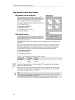
Fast counters
• Operating independently of each other,
of other operations and of the program
cycle
• Interrupt triggering when user select-
able counted values are reached – reac-
tion time from the detection of an input
signal to switching of an output is
300 µs
• 4-edge evaluation when incremental
position encoders are used for exact
positioning
Alarm inputs
• 4 independent inputs
• For registering signals in rapid succession
• Response time of 200 µs–500 µs for sig-
nal detection/300 µs for signal output
• Response to positive-going and/or neg-
ative-going signal edge
• Max. 16 interrupts in one queue de-
pending on prioritization
Feature CPU 221 CPU 222 CPU 224
CPU 224XP
CPU 224XPsi
CPU 226
Independent hardware counters 4 4 6 6
Independent alarm inputs 4 4 4 4
Pulse outputs 2 2 2 2
Time interrupts 1 to 250 ms 1 to 250 ms 1 to 250 ms 1 to 250 ms
Real-time clock optional optional integrated integrated
Binary processing speed 0.22 µs 0.22 µs 0.22 µs 0.22 µs
14
Great well-rounded technology
SITOP smart – optimally matched
to SIMATIC S7-200
SITOP smart is one of the narrowest DIN
rail mounted power supply units and ex-
hibits an impressive overload behavior.
Even high loads can be switched on with-
out any problems. Nominal outputs of
continuous 120 percent position the
power supplies as the most reliable of
their class. Numerous certifications sim-
plify their universal and worldwide use,
as well as their deployment under haz-
ardous conditions.
For tough customers: SIPLUS extreme
Operating under extreme conditions?
No problem! If you have to operate your
system in an extended temperature
range, require added condensation pro-
tection or demand other voltage ratings,
then SIPLUS extreme is the solution for
you. It lets you adapt your CPUs to your
special requirements.
Memory cartridge
EEPROM memory modules
A small optional EEPROM memory module can
save you a lot of time and cost. It makes it very
easy to copy, update or exchange your user
program on the device. And if necessary, you
can use this module to send a program quickly
and inexpensively to your customers. You just
shut off the power, plug in the module, turn it
all back on – and the program is instantly up-
dated. Whether project documentation, recipe
handling or data logging – our memory mod-
ules are available with 64 KB or 256 KB.
Available options
Project documentation
• Bitmap files, PDF files, DOC files
• Complete STEP 7-Micro/WIN projects can
be transferred to the memory card with
S7-200 Explorer – giving you onsite
access to the current user data at all
times even without STEP 7-Micro/WIN
Recipe handling
• Definition and download of the recipes,
e.g. production data, machine parame-
ters, etc.
• Better use of memory by occupying the
data memory in the CPU with only one
recipe: online updating and adaptation
Data logging
•
Dynamic storage, e.g. of performance or
statistics data and fault or error messages
• Optionally with time stamp
• Log file transferable to PC via S7-200
Explorer
Small and practical
Battery module
To ensure no user data is lost, you can
use the optional battery module for long-
term backups to extend backup time from
the roughly 5 days of internal backup to,
in general, a total of 200 days.
Real-time clock
Whether you need to count operating
hours, warm up rooms or attach a time
stamp to messages: the integrated real-
time clock on the S7-200 runs to the
minute and to the day via the software
according to your settings – even in leap
years. Including automatic daylight sav-
ing time switchover.
Analog potentiometers
With the integrated analog potentiome-
ters on the S7-200, you can optimize the
process sequence almost “according to
feel” without a PC or HMI. They let you
fine-tune the contents of data registries,
time values, preassigned counter values
or other parameters without meddling
with the program. This is a practical way,
for example, to change a welding time or
delay time quickly and directly.
15
Facts, facts, facts:
The CPUs
Identical technical specifications of the CPUs 221, 222, 224, 224XP, 224XPsi and 226:
Feature CPU 221, 222, 224, 224XP, 224XPsi, 226
32-bit floating-point math in accordance with IEEE standard yes
Fully configurable, integrated PID controller yes, up to 8 independent PID loops
Bit processing speed 0.22 µs
Time-controlled interrupts 2 (cycle time between 1 and 255 ms at 1 ms resolution)
Hardware interrupts (edge detection at inputs) max. 4 inputs
Flags, timers, counters 256 each
High-speed counters 4–6 (depending on CPU), max. 30 kHz, or 200 kHz with CPU 224 XP
Pulse outputs (pulse-width- or frequency-modulated) 2 outputs, 20 kHz each (for DC versions), 100 kHz with CPU 224 XP
Program and data memory retentive (non-volatile)
Storage of dynamic data after a power interruption retentive: non-volatile via internal high-performance capacitor and/or additional battery
module: loading of data lock with STEP 7-Micro/WIN, TD 200C or by user program to
integrated EEPROM
Backup of dynamic data with battery module typ. 200 days
Built-in serial port(s) yes, RS 485 interface supporting the following operating modes: PPI master or slave/MPI
slave/Freeport (freely configurable ASCII protocol), Modbus Master/Slave
Max. baud rate 187.5 kbaud (PPI/MPI) or 115.2 kbaud (Freeport)
Programming software STEP 7-Micro/WIN supports all standards such as STL, CSF or LAD
Optional program memory module yes, programmable in CPU, for program transmission, data logging, recipe, documentation
DC/DC/DC version yes
Supply voltage 24 V DC
Digital inputs 24 V DC
Digital outputs 24 V DC, max. 0.75 A, parallel connection possible for higher switching capacity
AC/DC/relay version yes
Supply voltage 85–264 V AC
Digital inputs 24 V DC
Digital outputs 5–30 V DC or 5–250 V AC, max. 2 A (relay)
Accessories
Cable RS 232 Smart Cable (Multimaster
1, 2, 3
) USB Smart Cable (Multimaster
4
)
Isolation yes yes
Power supply from CPU from USB Port
Supported protocols PPI and ASCII (Freeport); 10/11 bit PPI; 10/11 bit
PPI communication 9.6 k; 19.2 k; 187.5 k 9.6 k; 19.2 k; 187.5 k
Communication setting DIP switch; RS 232 automatically unnecessary
LED display yes yes
Required software STEP 7-Micro/WIN V3.2 from SP4 STEP 7-Micro/WIN V3.2 from SP4
1) as SIPLUS component also for extended temperature range –25 +70 °C and aggressive atmospheres/condensation (www.siemens.com/siplus)
2) RS 232 Smart Cable: for networks and external modems (including GSM and GPRS)
3) Settings, e.g. for modems, are stored permanently
4) USB Smart Cable: Multimaster for USB
16
Specific technical data on the CPUs:
Feature CPU 221
1
CPU 222
1
CPU 224
1
CPU 224XP
1
CPU 224XPsi
2
CPU 226
1
Integrated dig. inputs/outputs 6 DI/4 DO 8 DI/6 DO 14 DI/10 DO 14 DI/10 DO 24 DI/16 DO
Digital inputs/outputs/max. number of
channels with expansion modules – 48/46/94 114/110/224 114/110/224 128/128/256
Analog inputs/outputs/max. number of
channels with expansion modules – 16/8/16 32/28/44
2 AI/1 AO integrated
32/28/44 32/28/44
Program memory 4 KByte 4 KByte 8/12 KByte 12/16 KByte 16/24 KByte
Data memory 2 KByte 2 KByte 8 KByte 10 KByte 10 KByte
Storage of dyn. data
via high-performance capacitor typ. 50 h typ. 50 h typ. 100 h typ. 100 h typ. 100 h
High-speed counters 4 x 30 kHz,
of which 2 x 20 kHz
A/B counter usable
4 x 30 kHz,
of which 2 x 20 kHz
A/B counter usable
6 x 30 kHz,
of which 4 x 20 kHz
A/B counter usable
4 x 30 kHz, 2 x 200 kHz
of which 3 x 20 kHz +
1 x 100 kHz
A/B counter usable
6 x 30 kHz,
of which 4 x 20 kHz
A/B counter usable
Communications interfaces RS 485 1 1 1 2 2
Supported protocols: both interfaces both interfaces
– PPI master/slave yes yes yes yes yes
– MPI slave yes yes yes yes yes
– Freeport (freely config. ASCII protocol) yes yes yes yes yes
Optional communications possibilities not expandable yes, PROFIBUS DP Slave
and/or AS-Interface
Master/Ethernet/
Internet/Modem
yes, PROFIBUS DP Slave
and/or AS-Interface
Master/Ethernet/
Internet/Modem
yes, PROFIBUS DP Slave
and/or AS-Interface
Master/Ethernet/
Internet/Modem
yes, PROFIBUS DP Slave
and/or AS-Interface
Master/Ethernet/
Internet/Modem
Built-in 8-bit analog potentiometer 1 1 2 2 2
(for commissioning, value change)
Real-time clock optional optional yes yes yes
Integrated 24-V-DC sensor supply volt. max. 180 mA max. 180 mA max. 280 mA max. 280 mA max. 400 mA
Removable terminal strip – – yes yes yes
Dimensions (W x H x D in mm) 90 x 80 x 62 90 x 80 x 62 120.5 x 80 x 62 140 x 80 x 62 196 x 80 x 62
1) As SIPLUS component also for extended temperature range –25 +70 °C
and aggressive atmospheres/condensation (www.siemens.de/siplus)
2) CPU 224XPsi (current-sinking digital outputs)
17
Facts, facts, facts:
Digital expansions
Technical data:
Digital I/O modules EM 221
1
EM 222
1
EM 222
1
Number of inputs/outputs 8 DI (DC) 8 DO (DC) 8 DO (relay)
Number of inputs 8 – –
Input type 24 V DC – –
Sinking/sourcing x/x – –
Input voltage 24 V DC, max. 30 V – –
Isolation yes – –
In groups of 4 inputs – –
Number of outputs – 8 8
Output type – 24 V DC relay
Output current – 0.75 A in group-parallel connection
possible for higher switching capacity
2 A
Output voltage DC – 20.4–28.8 V 5–30 V
(permissible range) AC – – 5–250 V
Isolation – yes yes
In groups of – 4 outputs 4 outputs
Removable terminal strip yes yes yes
Dimensions (W x H x D in mm) 46 x 80 x 62 46 x 80 x 62 46 x 80 x 62
Digital I/O modules EM 221
1
EM 222 EM 222
Number of inputs/outputs 16 DI (DC) 4 DO (DC) 4 DO (relay)
Number of inputs 16 – –
Type of input 24 V DC – –
Sinking/sourcing x/x – –
Input voltage 24 V DC, max. 30 V – –
Isolation yes – –
In groups of 4 inputs – –
Number of outputs – 4 4
Output type – 24 V DC relay
Output current – 5 A max. per output, switchable
in parallel for greater power
10 A max. per output
Output voltage DC (permissible range) AC – 20.4–28.8 V 12–250 V
Isolation – yes yes
In groups of – 1 output 1 output
Removable terminal strip yes yes yes
Dimensions (W x H x D in mm) 71.2 x 80 x 62 46 x 80 x 62 46 x 80 x 62
1) As SIPLUS component also for extended temperature range –25 +70 °C
and aggressive atmospheres/condensation (www.siemens.com/siplus)
18
Technical data:
Digital I/O modules EM 223
1
EM 223
1
EM 223
1
EM 223
1
Number of inputs/outputs 4 DI (DC) / 4 DO (DC) 4 DI (DC) / 4 DO (relay) 8 DI (DC) / 8 DO (DC) 8 DI (DC) / 8 DO (relay)
Number of inputs 4 4 8 8
Input type 24 V DC 24 V DC 24 V DC 24 V DC
Sinking/sourcing x/x x/x x/x x/x
Input voltage 24 V DC, max. 30 V 24 V DC, max. 30 V 24 V DC, max. 30 V 24 V DC, max. 30 V
Isolation no no yes yes
In groups of 4 inputs 4 inputs 4 inputs 4 inputs
Number of outputs 4 4 8 8
Output type 24 V DC relay 24 V DC relay
Output current 0.75 A in
parallel connection
possible for higher
switching capacity
2 A 0.75 A in group-
parallel connection
possible for higher
switching capacity
2 A
Output voltage DC 20.4–28.8 V 5–30 V 20.4–28.8 V 5–30 V
(Permissible range) AC – 5–250 V – 5–250 V
Isolation no no yes yes
In groups of 4 outputs 4 outputs 4 outputs 4 outputs
Removable terminal strip yes yes yes yes
Dimensions (W x H x D in mm) 46 x 80 x 62 46 x 80 x 62 71.2 x 80 x 62 71.2 x 80 x 62
Digital I/O modules EM 223
1
EM 223
1
EM 223 EM 223
Number of inputs/outputs 16 DI (DC) / 16 DO (DC) 16 DI (DC) / 16 DO (relay) 32 DI (DC) / 32 DO (DC) 32 DI (DC) / 32 DO (relay)
Number of inputs 16 16 32 32
Input type 24 V DC 24 V DC 24 V DC 24 V DC
Sinking/sourcing x/x x/x x/x x/x
Input voltage 24 V DC, max. 30 V 24 V DC, max. 30 V 24 V DC, max. 30 V 24 V DC, max. 30 V
Isolation yes yes yes yes
In groups of 8 inputs 8 inputs 16 inputs 16 inputs
Number of outputs 16 16 32 32
Output type 24 V DC relay 24 V DC relay
Output current 0.75 A in group parallel
connection possible for
higher switching capacity
2 A 0.75 A in group parallel
connection possible for
higher switching capacity
2 A
Output voltage DC 20.4–28.8 V 5–30 V 20.4–28.8 V 5–30 V
(Permissible range) AC – 5–250 V – 5–250 V
Isolation yes yes yes yes
In groups of 4/4/8 outputs 4 outputs 16 outputs 11/11/10 outputs
Removable
terminal strip yes yes yes yes
Dimensions (W x H x D in mm) 137.3 x 80 x 62 137.3 x 80 x 62 196 x 80 x 62 196 x 80 x 62
19
Facts, facts, facts:
Analog expansions
Technical data:
Analog I/O modules EM 231
1
EM 231 EM 232
1
EM 232 EM 235
1
Number of inputs/outputs 4 AI 8 AI 2 AO 4 AO 4 AI/1 AO
Number of inputs 4 8 – – 4
Input type 0–10 V/0–20 mA 0–10 V/0–20 mA – – 0–10 V/0–20 mA
Voltage ranges 0–10 V, 0–5 V,
+/–5 V, +/–2.5 V
0–10 V, 0–5 V, +/–5 V,
+/–2.5 V (Ch 0 – 5)
0–10 V, 0–5 V, +/–5 V,
+/–2.5 V, 0–20 mA
(Ch 6 – 7)
– – 0–10 V, 0–5 V
Resolution 12 bit 12 bit – – 12 bit
Isolation no no – – no
Number of outputs – – 2 4 1
Output type – – +/–10 V, 0–20 mA +/–10 V, 0–20 mA +/–10 V, 0–20 mA
Resolution –
–
–
–
12 bit volt.,
11 bit current
12 bit volt.,
11 bit current
12 bit volt.,
11 bit current
Isolation – – no no no
Removable terminal strip no no no no no
Dimensions (W x H x D in mm) 71.2 x 80 x 62 71.2 x 80 x 62 46 x 80 x 62 71.2 x 80 x 62 71.2 x 80 x 62
Temperature measurement
modules
EM 231 TC
Thermocouples
EM 231 TC
Thermocouples
EM 231 RTD
Resistance type sensors
1
EM 231 RTD
Resistance type sensors
Number of inputs/outputs 4 AI 8 AI 2 AI 4 AI
Number of inputs 4 8 2 4
Input type Thermocouples
Type S, T, R, E, N, K, J
Voltage +/–80 mV
Thermocouples
Type S, T, R, E, N, K, J
Voltage +/–80 mV
Pt 100, 200, 500, 1000 ohm,
Pt 10.000,
Ni 10, 120, 1000 ohm,
R 150, 300, 600 ohm
Pt 100, 200, 500, 1000 ohm,
Pt 10.000,
Ni 10, 120, 1000 ohm,
R 150, 300, 600 ohm
Resolution 15 bit + sign 15 bit + sign 15 bit + sign 15 bit + sign
Isolation 500 V AC 500 V AC 500 V AC 500 V AC
Cold-junction compensation yes yes not nec. not nec.
Wiring two-wire two-wire two-, three- or four-wire two-, three- or four-wire
Max. wire length to sensor 100 m 100 m 100 m 100 m
Removable terminal strip no no no no
Dimensions (W x H x D in mm) 71.2 x 80 x 62 71.2 x 80 x 62 71.2 x 80 x 62 71.2 x 80 x 62
Temperature values in Centigrade or degrees Fahrenheit are available in the program as values with one decimal place.
1) as SIPLUS component also for extended temperature range –25 +70 °C and aggressive atmospheres/condensation (www.siemens.com/siplus)
20
Technical data:
Positioning module EM 253
Number of inputs 5 points (RP, LMT–, LMT+, ZP, STP)
Type of inputs active high/active low (IEC Type 1 sink, except ZP)
Number of integrated outputs 6 points (4 signals)
Type of outputs
P0+, P0–, P1+, P1–
P0, P1+, DIS, CLR
RS422/485 driver
Open drain
Switching frequency
P0+, P0–, P1+, P1– 200 kHz
Power supply:
L + supply voltage
Logic output voltage
L + supply current VS, 5 V DC load
Load current
0 mA (no load)
200 mA (rated load)
11 to 30 V DC
+5 V DC +/–10%, max. 200 mA
12 V DC Input
120 mA
300 mA
24 V DC Input
70 mA
130 mA
V DC Requirement +5 V DC/+24 V DC 190 mA/130 mA
Dissipation 2.5 W
Dimensions (W x H x D in mm) 71.2 x 80 x 62
Weight 190 g
SIWAREX MS weighing module
Communication interfaces SIMATIC S7 bus, RS 232, TTY
Measuring properties
• Fault limit acc. to DIN 1319-1 of the
measuring range end value at 20° ±10 K
• Internal resolution
data format of weight values
0.05 %
65,535
2 byte (fixed point)
Number of measurements/second 50 or 30
Load cells Strain gauges in 4-wire or 6-wire system
Load cell identifier 1 mV/V up to 4mV/V
Max. distance of load cells 500 m
Ex approvals and safety CE, ATEX 100, FM, UL, cULus Haz. Loc.s
Degree of protection acc. to DIN EN 60529; IEC 60529 IP20
V DC Requirement +5 V DC/+24 V DC 145 mA/max. 130 mA
Dimensions (W x H x D in mm) 71.2 x 80 x 62
21
Facts, facts, facts:
Human Machine Interface
Technical data:
Operator panels TD 100C TD 200
2
Display
Reflective LCD screen Backlit LCD screen
LCD Screen: Number of lines 4 2
Characters per line (max.) 16 (ASCII/Cyrillic),
8 (Chinese)
20 (ASCII/Cyrillic),
10 (Chinese)
Resolution 132 x 65 pixels 181 x 33 pixels
Operator controls
Membrane keyboard Membrane keyboard
Function keys (programmable) 14 configurable 8
System keys 65
Memory integrated (usable memory for user data) User data on CPU User data on CPU
Interfaces
1 PPI (RS 485)
for setup of a network with
max. 126 nodes
1 PPI (RS 485)
for setup of a network with
max. 126 nodes
Functionality
Signals
(freely definable signal classes)
40 80
Signal buffer (number of entries) – –
Mimic diagrams 32 64
Variables 208 864
Graphics objects – –
Numeric/alphabetic input •/– •/–
Password ••
Online languages 1 5
Bar charts (pixel graphics) – •
Degree of protection (front/rear) IP65, UL 50 Type 4X (when built in)/
IP20
IP65, UL 50 Type 4X (when built in)/
IP20
Dimensions
Front panel (W x H in mm) 89.6 x 76 148 x 76
Depth of device in mm 35.7 (max. 44 with fittings) 28
Certification CE, cULus, FM, C-Tick, ATEX CE, cULus, FM, C-Tick, ATEX
Supply voltage
24 V DC (from S7-200 CPU only) 24 V DC
Ambient conditions
Operating temperature
• vertical mounting
• max. angle of inclination
Transport/storage temperature
0 ºC to 60 ºC
0 ºC to 60 ºC
–20 ºC to 60 ºC
0 ºC to 60 ºC
0 ºC to 60 ºC
–20 ºC to 60 ºC
Weight
110 g 190 g
Configuration/programming
STEP 7-Micro/WIN 4.0 SP2 STEP 7-Micro/WIN 4.0
1) MTBF for backlighting (at 25 ºC): OP 73micro about 100,000 h, TP 177micro about 50,000 h
2) As SIPLUS component also for extended temperature range –25 +70 °C and aggressive atmospheres/condensation (www.siemens.com/siplus)
• possible
– not possible
22
TD 200C TD 400C OP 73micro TP 177micro
Backlit LCD screen Backlit LCD screen 3" LCD screen
1
5.7" LCD screen, STN,
Blue Mode, 4 blue stages
1
24––
20 (ASCII/Cyrillic),
10 (Chinese)
32 (ASCII/Cyrillic),
16 (Chinese)
––
181 x 33 pixels 192 x 64 pixels 160 x 48 pixels 320 x 240 pixels
(240 x 320 pixels for vertical
configuration of TP 177micro)
Membrane keyboard Membrane keyboard Membrane keyboard Touch screen
20 configurable 15 configurable 4 –
778–
User data on CPU User data on CPU 128 KB Flash 256 KB Flash
1 PPI (RS 485)
for setup of a network with
max. 126 nodes
1 PPI (RS 485)
for setup of a network with
max. 126 nodes
1 x RS 485 1 x RS 485
80 80 250 500
– – 128 (no battery backup) 128 (no battery backup)
64 64 250 250
864 864 500 250
icons icons bitmaps/icons/background images bitmaps/icons/background images
•/– •/– •/• •/•
••••
5555
••••
IP65, UL 50 Type 4X (when built in)/
IP20
IP65 (when built in)/
IP20
IP65 (when built in),
NEMA 4, NEMA 4X, NEMA 12/IP20
IP65 (when built in),
NEMA 4, NEMA 4X, NEMA 12/IP20
148 x 76 174 x 102 154 x 84 212 x 156
28 31 29 42
CE, cULus, FM, C-Tick, ATEX CE, cULus, C-Tick CE, cULus, C-Tick CE, cULus, FM, C-Tick, ATEX
24 V DC 24 V DC 24 V DC 24 V DC
0 ºC to 60 ºC
0 ºC to 60 ºC
–20 ºC to 60 ºC
0 ºC to 50 ºC
0 ºC to 50 ºC
–20 ºC to 60 ºC
0 ºC to 50 ºC
0 ºC to 40 ºC
–20 ºC to 60 ºC
0 ºC to 50 ºC
0 ºC to 40 ºC
–20 ºC to 60 ºC
200 g 310 g 250 g 750 g
STEP 7-Micro/WIN 4.0 STEP 7-Micro/WIN 4.0 SP6 from WinCC flexible Micro from WinCC flexible Micro
23
Facts, facts, facts:
The communication modules
Technical data
Communication modules EM 277 PROFIBUS DP slave module
1
CP 243-2 AS-Interface master module
Interface 1 communications interface RS 485 AS-Interface
Supported protocols: – MPI slave
– PROFIBUS DP slave
AS-Interface
Transmission rate 9,600 baud up to 12 Mbaud
adaptive
– max. 5 ms cycle time with 31 slaves
– max. 10 ms cycle time with 62 slaves
Connectable stations: – Text displays TD 100C, TD 200, TD 200C, TD 400C
– Operator panels, touch panels
– PG/PC with MPI interface (CPU download/
status via STEP 7-Micro/WIN possible)
– CPU S7-300/400
– PROFIBUS DP master or slaves
max. 62 AS-Interface slaves
Status displays CPU error, power, DP error, DX mode Status displays for slaves, error displays
Station address Adjustable on module (0–99) Not necessary
Galvanic isolation 500 V AC no
Max. cable length (without repeater) 1200 m (at 93.75 kbaud) 100 m
Removable terminal strip no no
V DC Requirement +5 V DC/+24 V DC 150 mA/max. 180 mA 220 mA/100 mA
Dissipation 2.5 W 3.7 W
Dimensions (W x H x D in mm) 71.2 x 80 x 62 71.2 x 80 x 62
Weight 175 g 250 g
Modem communication modules EM 241 modem module SINAUT MD 720-3
2
Analog telephone connection GPRS/GSM modem connection
Isolation
(phone line against Logic and …)
1500 V AC (galvanic) –
Cable connector RJ11 (6 points, 4-wire) SMA/50 ohm (antenna) RS 232, jack: D-SUB 9-pin
Modem standards Bell 103, Bell 212, V.21, V.22, V.22 bis,
V.23c, V.32, V.32 bis, V.34 (standard)
GPRS/CSD/quadband 850/900/1800/1900 MHz
V.24/V.28 (standard)
Safety features Password, callback –
Calling method Pulse or tone dialing –
Messaging protocols
(SMS)
Numerical
TAP (alphanumeric)
UCP commands 1, 30, 5
SMS/AT commands
–
Industrial standard protocols Mode RTU, PPI,
integrated functions for data exchange
–
V DC Requirement +5 V DC/+24 V DC 80 mA/70 mA 12–30 V DC (24 V DC nominal)
Dissipation 2.1 W 5.5 W
Dimensions (W x H x D in mm) 71.2 x 80 x 62 22.5 x 99 x 114
Weight 190 g 150 g
1) As SIPLUS component also for extended temperature range –25 +70 °C and aggressive atmospheres/condensation (www.siemens.com/siplus)
2) Quadband antenna ANT 794-4MR required
24
Ethernet/Internet communication modules CP 243-1 CP 243-1 IT
Transmission rate 10/100 Mbit/s 10/100 Mbit/s
Interfaces (connection to Industrial Ethernet) RJ45 RJ45
Supply voltage 24 V DC 24 V DC
V DC Requirement +5 V DC/+24 V DC 55 mA/60 mA 55 mA/60 mA
Dissipation 1.75 W 1.75 W
Dimensions (W x H x D in mm) 71.2 x 80 x 62 71.2 x 80 x 62
Weight 150 g 150 g
S7/PG communication
Number of operable connections 8 S7 connections + 1 PG connection 8 S7 connections + 1 PG connection
Configuration with STEP 7-Micro/WIN (V3.2 SP1 or later) with STEP 7-Micro/WIN (V3.2 SP3 or later)
IT communications
Number of connections to an e-mail server – 1
E-mail client – 32 e-mails with max. 1024 characters
Number of FTP/HTTP connections – 1/4
Adjustable access protection – 8 users
Memory capacity of the file system – 8 Mbytes
25