FX Series Programmable Controllers jy992d71801b
Bạn đang xem bản rút gọn của tài liệu. Xem và tải ngay bản đầy đủ của tài liệu tại đây (710.32 KB, 56 trang )
USER’S MANUAL
CC-Link INTERFACE BLOCK FX
2N
-32CCL
FX Series Programmable Controllers
Foreword
• This manual contains text, diagrams and explanations which will guide the reader in the correct installation and
operation of the FX
2N
-32CCL CC-Link Interface Block. It should be read and understood before attempting to
install or use the unit.
Further information can be found in the FX PROGRAMMING MANUAL, FX
0N
/FX
2N
/FX
2NC
series hardware man-
uals.
• If in doubt at any stage during the installation of the FX
2N
-32CCL CC-Link Interface Block always consult a profes-
sional electrical engineer who is qualified and trained to the local and national standards.
If in doubt about the operation or use of the FX
2N
-32CCL CC-Link Interface Block please consult the nearest Mit-
subishi Electric distributor.
• This manual is subject to change without notice.
FX
2N
-32CCL CC-Link Interface Block
i
FX
2N
-32CCL CC-Link INTERFACE BLOCK
USER’S MANUAL
Manual number : JY992D71801
Manual revision : B
Date : JANUARY 1999
FX
2N
-32CCL CC-Link Interface Block
ii
Guidelines for the safety of the user and protection of the FX
2N
-32CCL CC-Link Interface Block
This manual provides information for the installation and use of the FX
2N
-32CCL CC-Link Interface Block. The
manual has been written to be used by trained and competent personnel. The definition of such a person or
persons is as follows;
a ) Any engineer who is responsible for the planning, design and construction of automatic equipment
using the product associated with this manual should be of a competent nature, (trained and qualified
to the local and national standards required to fulfill that role). These engineers should be fully aware
of safety with regards to automated equipment.
b ) Any commissioning or service engineer must be of a competent nature, trained and qualified to the
local and national standards required to fulfill that job. These engineers should also be trained in the
use and maintenance of the completed product. This includes being completely familiar with all asso-
ciated documentation for the said product. All maintenance should be carried out in accordance with
established safety practices.
c ) All operators of the compliance product should be trained to use that product in a safe and coordi-
nated manner in compliance to established safety practices. The operators should also be familiar
with all documentation which is connected with the actual operation of the completed equipment.
Note:
The term ‘completed equipment’ refers to a third party constructed device which contains or uses the
product associated with this manual.
FX
2N
-32CCL CC-Link Interface Block
iii
Note’s on the symbology used in this manual
At various times through out this manual certain symbols will be used to highlight points of information which
are intended to ensure the users personal safety and protect the integrity of the equipment. Whenever any of
the following symbols are encountered, its associated note must be read and understood. Each of the sym-
bols used will now be listed with a brief description of its meaning.
Hardware warnings
Software warnings
1 ) Indicates that the identified danger
WILL
cause physical and property damage.
2 ) Indicates that the identified danger
POSSIBLY
cause physical and property damage.
3 ) Indicates a point of further interest or further explanation.
1 ) Indicates special care must be taken when using this element of software.
2 ) Indicates a special point of which the user of the associate software element should be aware.
3 ) Indicates a point of interest or further explanation.
FX
2N
-32CCL CC-Link Interface Block
iv
Memo
FX
2N
-32CCL CC-Link Interface Block Contents
v
CONTENTS
1. Introduction 1-1
1.1 Outline of product 1-1
1.2 Connection to CC-Link 1-3
1.3 System configuration of entire CC-Link 1-4
2. Product Specifications 2-1
2.1 Outside dimensions and nomenclature 2-2
2.2 General specifications and performance specifications 2-3
3. Connection and Wiring 3-1
3.1 Connection to PC 3-1
3.2 Wiring of power supply 3-2
3.3 Wiring of CC-Link 3-3
4. Setting of Remote Device Stations 4-1
4.1 Setting of station Nos., number of stations and transmission speed 4-1
4.2 List of number of remote points and remote Nos. 4-3
5. Assignment of Buffer Memory (BFM) 5-1
5.1 Outline of data communication 5-1
5.2 BFM dedicated to read 5-2
5.3 BFM dedicated to write 5-8
5.4 System area of remote I/O 5-12
5.5 Contents of errors 5-14
6. Programming Examples 6-1
6.1 System configuration 6-1
6.2 Flow of communication data 6-3
FX
2N
-32CCL CC-Link Interface Block
Contents
vi
6.3 Program in master PC 6-5
6.4 Program in FX PC 6-11
FX
2N
-32CCL CC-Link Interface Block Introduction 1
1-1
1. Introduction
The CC-Link interface block FX
2N
-32CCL is an interface block which connects the FX
0N
/FX
2N
/FX
2NC
PC to
the CC-Link.
1.1 Outline of product
Applicable PC
The FX
2N
-32CCL can be connected as a special extension block of the FX
0N
/FX
2N
/FX
2NC
Series micro PC.
Control instruction
The buffer memory of the FX
2N
-32CCL is read and written by FROM/TO instructions.
Connection to CC-Link
The FX
2N
-32CCL is connected as a remote device station to the CC-Link system.
Shielded twisted pair cables are used for wiring.
Number of I/O points
Eight I/O points (including input and output) are occupied in the FX PC.
However, the capacity of the 5 V DC power supplied from the PC is limited.
The current consumption of 5 V DC in the FX
2N
-32CCL is 130 mA. Make sure that the total current consump-
tion of 5 V DC including other special blocks does not exceed the criteria.
Station No. and number of stations
Station No. : 1 to 64 (rotary switch)
Number of stations: 1 to 4 (rotary switch)
FX
2N
-32CCL CC-Link Interface Block Introduction 1
1-2
Transmission speed
Transmission distance
10 Mbps : 100 m
5 Mbps : 150 m
2.5 Mbps : 200 m
625 kbps : 600 m
156 kbps : 1,200 m
Detailed specifications conform to the CC-Link system common specifications.
Number of remote points
The number of remote I/O points in one station is 32 input points and 32 output points. However, the upper 16
points of the final station are occupied by the CC-Link system as the system area.
The number of remote registers in one station is 4 points of RW write area and 4 points of RW read area.
Because the number of stations can be selected within the range of 1 to 4, the system can be constructed in
accordance with the control size.
FX
2N
-32CCL CC-Link Interface Block Introduction 1
1-3
1.2 Connection to CC-Link
The FX PC connected with the interface block FX
2N
-32CCL functions as a remote device station in the CC-
Link system.
One to four FX
2N
-32CCL units can be used at a time, and station Nos. not assigned to these FX
2N
-32CCL
units should be assigned to other remote device stations, remote I/O stations and local stations.
The number of connectable units, the transmission speed, the transmission distance, etc. conform to the CC-
Link system common specifications.
Terminal resistor
Terminal resistor
Shielded twisted pair cable
Remote device station
FX
0N
/FX
2N
/FX
2NC
Series
PC + FX
2N
-32CCL
Remote device station
FX
0N
/FX
2N
/FX
2NC
Series
PC + FX
2N
-32CCL
Remote I/O station Remote device station
CC-Link master station
Local station
FX
2N
-32CCL CC-Link Interface Block Introduction 1
1-4
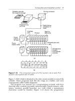
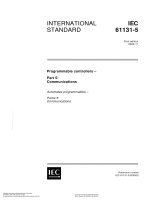
1.3 System configuration of entire CC-Link
The figure below shows the system configuration of the entire CC-Link.
For the details, refer to the user manual of the master unit in the CC-Link system.
RS-232C
interface unit
AJ65BT-R2
Remote I/O unit
AJ65BTB
AJ65BTC
Analog-digital
converter unit
AJ65BT-64AD
Local station
A1SJ61BT11
AJ61BT11
Local station
A1SJ61BT11
AJ61BT11
Master station
Shielded twisted pair cable
Terminal resistor (essential)
Terminal resistor (essential)
Shielded twisted pair cable
Intelligent device
station
Remote device station
Remote I/O station
Up to 64 units
Up to 26 units
Up to 26 units
Up to 42 units
64 units in all
A1SJ61QBT11
AJ61QBT11
FX PC
FX
0N
/FX
2N
/FX
2NC
Series
+ FX
2N
-32CCL
FX
2N
-32CCL CC-Link Interface Block Specifications 2
2-1
2. Product Specifications
Cautions on design
• For the status of each station in the case in which the PC CPU stops its operation or communica-
tion error has occurred in the data link, read thoroughly the contents of "5.
Data Link Processing Time" of the user manual of the master unit.
Construct an interlock circuit in a PC program so that the system can operate conservatively using
the communication status information (SB, SW).
If the interlock circuit is not correctly constructed, wrong output or malfunction may occur, and an
accident may occur at the end.
- Receive data from the master station or a local station in which a data link error has occurred
1 ) Remote input (RX), remote output (RY)
The data varies depending on setting of the condition set switch on the unit and setting of the
input data (SW4) in a station in which a data link error has occurred.OFF: Data is cleared (All
OFF).
ON: The data just before an error occurred is held.
2 ) Remote register (RWw, RWr), remote input (RX), remote output (RY)
The data just before an error occurred is held without regard to setting of the SW4.
• Never bind the communication cable together with the main circuit, the power cable, etc. Never
locate the communication cable near the main circuit, the power cable, etc.
Keep the communication cable by 100 mm or more from the main circuit, the power cable, etc. If
this distance is not kept, malfunction may occur due to noise.
FX
2N
-32CCL CC-Link Interface Block Specifications 2
2-2
2.1 Outside dimensions and nomenclature
Outer paint color: Munsell 0.08GY/7.64/0.81 Weight: Approx.200 g
Accessories: Special block No. label.
POWER LED : Lit when 5 VDC power is supplied from the PC main unit.
L RUN LED : Lit while communication is performed correctly.
L ERR LED : Lit when a communication error has occurred.
Lit when a rotary switch is incorrectly set. Flickers when setting of a rotary switch is changed
while the power is turned on.
RD LED : Lit while data is received.
SD LED : Lit while data is sent.
Extension
cable
2-
φ
4.5(0.18)
Mounting
hole
DIN rail
35mm(1.38)
mounting
bezel
M3(0.12)
terminal screw
External 24 VDC
ground terminal
Station No.
set switch
Number of
occupied
stations
set switch
Next step
extension
connector
Baud rate
set switch
4(0.16)
43(1.69)
90(3.54)
87(3.42)
80(3.15)
POWER
FX2N-32CCL
LRUN LERR RD SD
(inches)
[Front face of top cover] [Side] [Inside of top cover]
FX
2N
-32CCL CC-Link Interface Block Specifications 2
2-3
2.2 General specifications and performance specifications
General specifications
Dielectric strength:500 VAC for 1 min (between external terminals as a whole and ground terminal) Other
specifications are equivalent to those of the PC basic unit.
Performance specifications
Item Specifications of FX
2N
-32CCL
Drive power supply
24 VDC+/-10%, 50 mA (supplied from external terminal)
Control power supply
5 VDC, 130 mA (supplied from PC via extension cable)
Insulation method
Network bus and internal power supply are insulated each other by photocoupler.
Station type
Remote device station
Station No.
Number of stations
Station No.: 1 to 64 (set by rotary switch)
Number of remote
device points
Number of remote
register points
The number of remote I/O points in one station is 32 input points and 32 output points.
However, the upper 16 points are occupied by the CC-Link system as the system area.
The number of remote register points in one station is 4 points of RW write area and 4
points of RW read area.
For the details of the number of remote points and the remote Nos. in accordance with
setting of the number of stations, refer to "4.2 List of number of remote points and
remote Nos."
0
5
1
2
3
4
9
8
7
6
STATION
No.
✕
10
✕
1
10's digit
0
5
1
2
3
4
9
8
7
6
1's digit
OCCUPY
STATION
0
5
1
2
3
4
9
8
7
6
0, 65 to 99: Setting error
0: 1 station 1: 2 stations
2: 3 stations 3: 4 stations
4 to 9: Not available
Number of stations: 1 to 4 (set by rotary switch)
FX
2N
-32CCL CC-Link Interface Block Specifications 2
2-4
Transmission speed
156 kbps, 625 kbps, 2.5 Mbps, 5 Mbps, 10 Mbps (set by rotary switch)
Maximum
transmission distance
It varies depending on the transmission speed.
1 )The cable length between the master/local station and an adjacent station should be
2 m or more without regard to setting of the transmission speed.
2 )When the transmission speed is 5 Mbps or 10 Mbps, the maximum transmission dis-
tance varies depending on the cable length between remote I/O stations and remote
device stations.
Item Specifications of FX
2N
-32CCL
B RATE
0
5
1
2
3
4
9
8
7
6
0: 156 kbps 1: 625 kbps 2: 2.5 Mbps
3: 5 Mbps 4: 10 Mbps 5 to 9: Setting error
Master station
Remote I/O
station
Remote
device station
Local station Local station
Remote I/O
station
Remote
device station
Remote I/O
station
Remote
device station
Maximum transmission distance
①②①②
Remote I/O
station
Remote
device station
①
FX PC functions as a remote device station.
Transmission
speed
•
••
• ‚
‚‚
‚
Maximum transmission
distance
156kbps
2 m or more
30 cm or more 1200 m
625kbps
30 cm or more 600 m
2.5Mbps
30 cm or more 200 m
5Mbps
60 cm or more 150 m
30 to 59 cm 110 m
10Mbps
1 m or more 100 m
60 to 99 cm 80 m
30 to 59 cm 50 m
FX
2N
-32CCL CC-Link Interface Block Specifications 2
2-5
Operation indication
LEDs (POWER, L RUN, L ERR, RD, SD)
Number of occupied
I/O points
Eight I/O points (including input and output) of FX PC
Applicable PC
FX
0N
, FX
2N
, FX
2NC
Series PC
Communication with
PC
Communication is performed from the FX PC via the buffer memory using FROM/TO
instructions.
Item Specifications of FX
2N
-32CCL
FX
2N
-32CCL CC-Link Interface Block Specifications 2
2-6
Memo
FX
2N
-32CCL CC-Link Interface Block Connection and Wiring 3
3-1
3. Connection and Wiring
3.1 Connection to PC
Connection of extension cable
The FX
2N
-32CCL can be connected directly to the FX
0N
/
2N
PC main unit or connected on the right side of an
other extension block or extension unit.
Up to eight special units/blocks can be connected, and the unit No. 0 to 7 is assigned from the one nearest to
the basic unit.
However, the capacity of the 5 VDC power supplied from the PC is limited. The current consumption of 5 VDC
of the FX
2N
-32CCL is 130 mA. Make sure that the total current consumption of 5 VDC including other special
blocks does not exceed the criteria.
POWER
FX2N-32CCL
724561302720 22 23 24 25 2621
1611 1514 1710 12 13
14 171510 12 13
724561302720 22 23 24 25 2621
1611
OUT
IN
L X5 X7 X13 X15 X17 X21 X23 X25
X4 X6 X10 X14 X16 X20 X22 X24
24+N
COM X0
X1
X2
COM4
Y24
Y25
COM5
Y27COM2
Y4
Y5
Y6
Y7 COM3
Y10
Y13COM1
Y0 Y2
Y3
Y14
Y15
Y20
Y21
Y22
Y23
Y26
POWER
BATT.V
RUN
CPU.E
PROG.E
1
IN 0
7
2
3
4
5
6
POWER
1
IN 0
7
2
3
4
5
6
FX
2N
-48MR
FX
2N
-16EX
POWER
FX2N-32CCL
FX
2N
-48MR-ES/UL
X000~X027
Y000~Y027
FX
2N
-32CCL
special block
FX
2N
-32CCL
special block
FX
2N
-16EX
-ES/UL
X030~X047
No.0
No.1
LRUN LERR RD SD
LRUN LERR RD SD
FX
2N
-32CCL CC-Link Interface Block Connection and Wiring 3
3-2
3.2 Wiring of power supply
Wiring
Handling of crimp-style terminal
COM
24+
PC main unit
Extension cable
FX
2N
-32CCL
24+
24-
24 VDC service power
supply for PC can be used
instead.
Service power
supply for sensor
Grounding resistor
100
Ω
or less
(class 3)
24 VDC+/-10%,
50 mA
6.2mm
(0.24)
6.2mm
(0.24)
• Use crimp-style terminals of the dimensions shown in the figure on the
left.
• The terminal tightening torque should be 0.5 to 0.8 N
Ÿ
m (5 to 8 kgf
Ÿ
cm)
Tighten terminals securely so that malfunction will not occur.
FX
2N
-32CCL CC-Link Interface Block Connection and Wiring 3
3-3
3.3 Wiring of CC-Link
Specifications of twisted pair cable
This paragraph describes a recommended twisted cable usable in the CC-Link.
If any cable other than the recommended one shown in the table below is used, the performance of the CC-
Link is not assured.
The table below shows the model name and the specifications of the recommended cable.
About the shielded twisted pair cables, consult the nearest MITSUBISHI ELECTRIC CORPORATION service
center.
Item
Specifications
Model name
Cable type
Conductor cross sectional area
Withstand voltage
Electrostatic capacity (kHz)
Characteristic impedance (1 MHz)
Cross section
Outside dimensions
Approximate weight
FANC-SB 0.5mm
2
✕
3
Shielded twisted pair cable
0.5mm
2
37.8
Ω
/km or less
10,000 M
Ω
-km or more
500 VDC, 1 min
100±15
Ω
7mm
65kg/km
Conductor resistance (20°C)
Insulation resistance
60 nF/km or less
Aluminum
tape
DA
DB
DG
Shield
Sheath
Ground cable
Blue
White
Yellow
FX
2N
-32CCL CC-Link Interface Block Connection and Wiring 3
3-4
Wiring of twisted pair cable
Wire the FX
2N
-32CCL and the CC-Link using shielded twisted pair cables as shown in the figure below.
• Connect the terminals DA and DA, DB and DB as well as DG and DG of each station with shielded
twisted pair cables. Because two DA terminals and two DB terminals are provided in the FX
2N
-32CCL,
a next station can be easily connected.
• Connect the SLD terminal of each station to a shield of a shielded twisted pair cable.
• Perform Class 3 grounding to the FG terminal of each station.
• Wiring of each station can be performed from any point without regard to the station No.
• When the FX
2N
-32CCL is used as the terminal station, connect a terminal resistor between the terminals
DA and DB of the FX
2N
-32CCL. The terminal resistor is packed together with the Master unit.
• The maximum transmission distance and the distance between stations in the CC-Link system vary
depending on the selected transmission speed. For the details, refer to the maximum transmission dis-
tance described in "2.2 General specifications and performance specifications" or the specifications
described in the manual of the CC-Link master unit.
DA
DB
DG
SLD
FG
DA
DA
DB
DB
DG
SLD
FG
DA
DB
DG
SLD
FG
Class 3
grounding
Class 3
grounding
Terminal
resistor
Terminal
resistor
Master
unit
FX
2N
-32CCL
Remote I/O
unit
Shielded twisted
pair cable
Class 3
grounding
FX
2N
-32CCL CC-Link Interface Block Setting of Remote Device Stations 4
4-1
4. Setting of Remote Device Stations
4.1 Setting of station Nos., number of stations and transmission speed
Setting the rotary switch
The station No., the number of stations and the transmission speed can be set using rotary switches provided
inside the panel cover of the FX
2N
-32CCL.
Setting of each rotary switch becomes valid when the power of the FX PC is turned on.
Set each rotary switch while the power of the PC is turned off. If setting of a rotary switch (except the rotary
switch for the number of stations) is changed while the power of the PC is turned on, the L ERR LED is lit.
0
5
1
2
3
4
9
8
7
6
STATION
No.
✕
10
✕
1
10's digit
0
5
1
2
3
4
9
8
7
6
1's digit
1)Station No.
set switch
2)Number of
occupied stations
set switch
3)Baud rate
set switch
0
5
1
2
3
4
9
8
7
6
0
5
1
2
3
4
9
8
7
6
0
5
1
2
3
4
9
8
7
6
0
5
1
2
3
4
9
8
7
6
STATION
NO.
POWER
B RATE
0 1st.
1 2st.
2 3st.
3 4st.
0 156K
1 625K
2 2.5M
3 5M
4 10M
OCCUPY
STATION
32CCL
x10
x1
OCCUPY
STATION
0
5
1
2
3
4
9
8
7
6
Set the station No. within the range of 1 to 64.
One to four FX
2N
-32CCL units can be used at a
time. Pay attention so that the station
No. set here is not assigned to an other unit.
0, 65 to 99: Setting error
1 ) Station No.: 1 to 64
Numerics 1 to 3 correspond to 1 to 4 stations
respectively.
0: 1 station 3: 4 stations
1: 2 stations 4 to 9: Not available
2: 3 stations
The number of remote device points is deter-
mined by the number of stations set here.
(☞ 4.2)
2 ) Number of stations: 1 to 4
FX
2N
-32CCL CC-Link Interface Block Setting of Remote Device Stations 4
4-2
B RATE
0
5
1
2
3
4
9
8
7
6
Numerics 0 to 4 correspond to 156 kbps to10
Mbps respectively.
0: 156 kbps 3: 5 Mbps
1: 625 kbps 4: 10 Mbps
2: 2.5 Mbps 5 to 9: Setting error
Set the transmission speed in accordance with
the specifications of the maximum
transmission distance and the transmission
speed. (☞ 2.2)
3 ) Baud rate (transmission speed): 156 kbps, 625 kbps, 2.5 Mbps, 5 Mbps, 10
Mbps
FX
2N
-32CCL CC-Link Interface Block Setting of Remote Device Stations 4
4-3
4.2 List of number of remote points and remote Nos.
In the FX
2N
-32CCL, the number of remote points vary depending on the selected number of stations (1 to 4).
• Thirty-two remote input points and 32 remote output points are available in one station. However, the
upper 16 points of the final station are occupied by the CC-Link as the system area.
• Four read points and four write points are available as remote registers in one station.
Table of number of remote points and remote Nos. in accordance with selected number of stations
Number
of
stations
Type Remote input Remote output
Remote register for
write
Remote register for
read
1
User area
RX00 to RX0F
(16 points)
RY00 to RY0F
(16 points)
RWr0 to RWr3
(4 points)
RWw0 to RWw3
(4 points)
System area
RX10 to RX1F
(16 points)
RY10 to RY1F
(16 points)
2
User area
RX00 to RX2F
(48 points)
RY00 to RY2F
(48 points)
RWr0 to RWr7
(8 points)
RWw0 to RWw7
(8 points)
System area
RX30 to RX3F
(16 points)
RY30 to RY3F
(16 points)
3
User area
RX00 to RX4F
(80 points)
RY00 to RY4F
(80 points)
RWr0 to RWrB
(12 points)
RWw0 to RWwB
(12 points)
System area
RX50 to RX5F
(16 points)
RY50 to RY5F
(16 points)
4
User area
RX00 to RX6F
(112 points)
RY00 to RY6F
(112 points)
RWr0 to RWrF
(16 points)
RWw0 to RWwF
(16 points)
System area
RX70 to RX7F
(16 points)
RY70 to RY7F
(16 points)