FX Series Programmable Controllers jy992d65301d
Bạn đang xem bản rút gọn của tài liệu. Xem và tải ngay bản đầy đủ của tài liệu tại đây (1.62 MB, 68 trang )
FX-1PG/FX
2N
-1PG PULSE GENERATOR UNIT
USER'S MANUAL
FX-1PG/FX
2N
-1PG PULSE GENERATOR UNIT
USER'S MANUAL
Foreword
•
This manual contains text, diagrams and explanations which will guide the reader in the correct installation, safe use and
operation of the FX-1PG/FX
2N
-1PG pulse generator unit. It should be read and understood before attempting to install or
use the unit.
Further information can be found in the FX PROGRAMMING MANUAL, FX/FX
2N
series hardware manuals.
•
If in doubt at any stage during the installation of the FX-1PG/FX
2N
-1PG pulse generator unit always consult a professional
electrical engineer who is qualified and trained to the local and national standards.
If in doubt about the operation or use of the FX-1PG/FX
2N
-1PG pulse generator unit please consult the nearest Mitsubishi
Electric distributor.
•
This manual is subject to change without notice.
FX-1PG/FX
2N
-1PG PULSE GENERATOR UNIT
USER’S MANUAL
FX-1PG/FX
2N
-1PG PULSE GENERATOR UNIT
Manual number: JY992D65301
Manual revision: D
Date: July 2000
FX-1PG/FX
2N
-1PG PULSE GENERATOR UNIT
i
USER’S MANUAL
FX-1PG/FX
2N
-1PG PULSE GENERATOR UNIT
Manual number: JY992D65301
Manual revision: D
Date: July 2000
FX-1PG/FX
2N
-1PG PULSE GENERATOR UNIT
i
Guidelines for the safety of the user and protection of the FX-1PG/FX
2N
-1PG
pulse generator unit
This manual provides information for the installation and use of the FX-1PG/FX
2N
-1PG pulse generator unit. The manual has
been written to be used by trained and competent personnel. The definition of such a person or persons is as follows;
a) Any engineer who is responsible for the planning, design and construction of automatic equipment using the product
associated with this manual should be of a competent nature, (trained and qualified to the local and national standards
required to fulfill that role). These engineers should be fully aware of all aspects of safety with regards to automated
equipment.
b) Any commissioning or service engineer must be of a competent nature, trained and qualified to the local and national
standards required to fulfill that job. These engineers should also be trained in the use and maintenance of the
completed product. This includes being completely familiar with all associated documentation for the said product. All
maintenance should be carried out in accordance with established safety practices.
c) All operators of the compliance product should be trained to use that product in a safe and coordinated manner in
compliance to established safety practices. The operators should also be familiar with all documentation which is
connected with the actual operation of the completed equipment.
Note: The term ‘completed equipment’ refers to a third party constructed device which contains or uses the product
associated with this manual.
FX-1PG/FX
2N
-1PG PULSE GENERATOR UNIT
ii
Note’s on the symbology used in this manual
At various times through out this manual certain symbols will be used to highlight points of information which are intended to
ensure the users personal safety and protect the integrity of the equipment. Whenever any of the following symbols are
encountered, its associated note must be read and understood. Each of the symbols used will now be listed with a brief
description of its meaning.
Hardware warnings
1) Indicates that the identified danger WILL cause physical and property damage.
2) Indicates that the identified danger could POSSIBLY cause physical and property damage.
3) Indicates a point of further interest or further explanation.
Software warnings
4) Indicates special care must be taken when using this element of software.
5) Indicates a special point of which the user of the associate software element should be aware.
6) Indicates a point of interest or further explanation.
FX-1PG/FX
2N
-1PG PULSE GENERATOR UNIT
iii
CONTENTS
1. INTRODUCTION 1-1
1.1 Introduction 1-1
2. OUTSIDE DIMENSIONS 2-1
2.1 Outside Dimensions 2-1
3. TERMINAL ARRANGEMENT 3-1
3.1 Terminal Arrangement and LED Indication 3-1
4. SPECIFICATIONS 4-1
4.1 Specifications 4-1
5. BFM LIST 5-1
5.1 BFMList 5-1
5.2 System of Units and Parameter Setting 5-3
5.3 Speed Data and Position Data 5-6
5.4 Position Data, Home Position and Current Position 5-9
5.5 Operation Command 5-10
5.6 Status and Error Codes 5-13
6. OUTLINE OF OPERATION MODES 6-1
6.1 JOG Operation and Machine Home Position Return Operation 6-1
6.1.1 DOG Switch 6-2
6.1.2 Overshoot Detection Home Return Positioning Method 6-3
6.1.3 Undershoot Detection Home Return Positioning Method 6-4
6.1.4 Home Position Return Operation 6-5
FX-1PG/FX
2N
-1PG PULSE GENERATOR UNIT
iv
6.2 Single-Speed Positioning Operation and Interrupt Single-Speed Positioning Operation 6-6
6.3 Two-Speed Positioning Operation and External Command Positioning Operation 6-7
6.4 Variable Speed Operation 6-8
6.5 Common Matter for Operation Modes 6-9
6.6 Connection of DOG and STOP Inputs and Handling of Limit Switches for Limit Detection . 6-10
6.7 Various Operation Modes and Buffer Memory Setting 6-12
7. OUTLINE OF FROM/TO INSTRUCTION (PC) 7-1
7.1 FROM/TO Instruction 7-1
8. I/O SPECIFICATIONS 8-1
8.1 I/O Specifications 8-1
9. EXTERNAL CONNECTION EXAMPLES 9-1
9.1 Example of Connection Between FX-1PG and Stepper Motor 9-1
9.2 Example of Connection Between FX
2N
-1PG and Stepper Motor 9-3
9.3 Example of External Connection (MR-C Servo Amplifier) 9-5
9.4 Example of External Connection (MR-J Servo Amplifier) 9-7
9.5 Example of External Connection (MR-J2 Servo Amplifier) 9-9
9.6 Example of External Connection (MR-H Servo Amplifier) 9-11
10.PROGRAM EXAMPLES 10-1
10.1 The reciprocation by single-speed positioning 10-1
11.DIAGNOSTICS 11-1
11.1 Preliminary Checks and Error Indication 11-1
FX-1PG/FX
2N
-1PG PULSE GENERATOR UNIT
v
MEMO
FX-1PG/FX
2N
-1PG PULSE GENERATOR UNIT
vi
MEMO
FX-1PG/FX
2N
-1PG PULSE GENERATOR UNIT
vi
1.
INTRODUCTION
1.1
Introduction
•
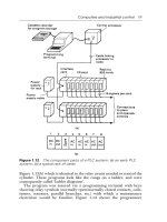
The FX-1PG/FX
2N
-1PG pulse generator unit (hereinafter referred to as “PGU”) performs simple positioning of an
independent axis (not interpolation control between multiple axes) by supplying a prescribed quantity of pulses (100 kHz
maximum) to drive amplifiers for servo or stepper motors.
•
The FX-1PG is attached as an extension to the FX/FX
2C
series programmable controller (hereinafter referred to as “PC”),
and the FX
2N
-1PG is attached as an extension to the FX
2N
series PC. Each PGU functions as a special block which
transfers data with the PC using the FROM/TO instructions, and occupies 8 points of inputs or outputs. Up to 8 PGU
units can be connected to single PC so operation for independent 8 axes can be realized.
•
The PGU provides connection terminals for positioning operations that require high-velocity responses as well as those
used for pulse train outputs. Other general I/O operations are controlled via the PC.
•
Because all the program for positioning control are executed in the PC, the PGU does not require dedicated teaching
panel, etc. As the programming tools for the PC, the following devices are available without modification.
➀ FX-10P-E and FX-20P-E
➁ General-purpose personal computer (IBM)
•
Various data access units as follows can be connected to the PC to set or display the positioning data.
➀ FX-10DU-E and FX-20DU-E
➁ FX-25DU-E, FX-30DU-E, FX-40DU-ES, FX-40DU-TK-ES and FX-50DU-TK(S)-E
Various
programming tools
Various data
access units
Servo motor
or
stepper motor
Drive
amplifier
FROM
TO
Control
panel
Machine
Pulse train
High-velocity I/O
FX
/FX2C/FX2NSeries PC
Control I/O
PGU FX-1PG/
FX
2N-1PG
1
FX-1PG/FX
2N
-1PG PULSE GENERATOR UNIT INTRODUCTION
1-1
1.
INTRODUCTION
1.1
Introduction
•
The FX-1PG/FX
2N
-1PG pulse generator unit (hereinafter referred to as “PGU”) performs simple positioning of an
independent axis (not interpolation control between multiple axes) by supplying a prescribed quantity of pulses (100 kHz
maximum) to drive amplifiers for servo or stepper motors.
•
The FX-1PG is attached as an extension to the FX/FX
2C
series programmable controller (hereinafter referred to as “PC”),
and the FX
2N
-1PG is attached as an extension to the FX
2N
series PC. Each PGU functions as a special block which
transfers data with the PC using the FROM/TO instructions, and occupies 8 points of inputs or outputs. Up to 8 PGU
units can be connected to single PC so operation for independent 8 axes can be realized.
•
The PGU provides connection terminals for positioning operations that require high-velocity responses as well as those
used for pulse train outputs. Other general I/O operations are controlled via the PC.
•
Because all the program for positioning control are executed in the PC, the PGU does not require dedicated teaching
panel, etc. As the programming tools for the PC, the following devices are available without modification.
➀ FX-10P-E and FX-20P-E
➁ General-purpose personal computer (IBM)
•
Various data access units as follows can be connected to the PC to set or display the positioning data.
➀ FX-10DU-E and FX-20DU-E
➁ FX-25DU-E, FX-30DU-E, FX-40DU-ES, FX-40DU-TK-ES and FX-50DU-TK(S)-E
Various
programming tools
Various data
access units
Servo motor
or
stepper motor
Drive
amplifier
FROM
TO
Control
panel
Machine
Pulse train
High-velocity I/O
FX
/FX2C/FX2NSeries PC
Control I/O
PGU FX-1PG/
FX
2N-1PG
1
FX-1PG/FX
2N
-1PG PULSE GENERATOR UNIT INTRODUCTION
1-1
2.
OUTSIDE DIMENSIONS
2.1
Outside Dimensions
FX-1PG
Mass(Weight): Approx. 0.3 kg (0.66 lbs)
Terminal screw: M3.5
Terminal screw tightening torque:
0.5 to 0.8 N⋅m
Applicable terminals:
Accessories: No. labels for special modules
Dimenssions : mm (inch)
•
The PGU is installed to the right side of a
main unit or an extension unit of an
FX/FX
2C
Series PC or of an other extension block. The PGU can be installed using a DIN rail (DIN 46277, Width: 35 mm)
or directly installed using M4 screws.
(For the details, refer to the handy manual packed together with the main unit.)
STOP
DOG
PG0
FP
RP
CLR
ERR
POWER
POWER
STOP
DOG
PG0
FP
RP
CLR
ERR
1PG
COM1
FPVH RP
RP0
CLR
FP0VL
VL
COM0
SG PG0-
STOP
DOG
S/S PG0+
45(1.77)
140(5.51)
95(3.74)
125(4.92) Mounting holes
Attachment groove
35mm Wide
DIN 46277 rail
10(0.39)
Mounting holes
35(1.38)
For M3.5
6.8(0.27)
or less
6.8(0.27)
or less
2
FX-1PG/FX
2N
-1PG PULSE GENERATOR UNIT OUTSIDE DIMENSIONS
2-1
FX2N-1PG
Mass(Weight): Approx. 0.2 kg (0.44 lbs)
Terminal screw: M3
Terminal screw tightening torque:
0.5 to 0.8 N⋅m
Applicable terminals:
Accessories: No. labels for special modules
Dimenssions : mm (inch)
•
The PGU is installed to the right side of a main unit or an extension unit of an FX
2N
Series PC or of an other extension
block. The PGU can be installed using a DIN rail (DIN 46277, Width: 35 mm) or directly installed using M4 screws. (For
the details, refer to the handy manual packed together with the main unit.)
POWER
CLR
POWER
1PG
STOP
S/S
DOG
COM1
PG0+
FP
VIN
RP
COM0
PG0-
87(3.39)
90(3.51)
43(1.68)
S/S
S
P
O
T
G
O
D
O
G
P
E
P
F
R
P
R
R
L
C
R
uhm
80(3.12)
Attachment groove
35mm Wide
DIN 46277 rail
9(0.35)
4(0.16)
For M3
6.2(0.24)
or less
6.2(0.24)
or less
2
FX-1PG/FX
2N
-1PG PULSE GENERATOR UNIT OUTSIDE DIMENSIONS
2-2
3.
TERMINAL ARRANGEMENT
3.1
Terminal Arrangement and LED Indication
FX-1PG FX
2N
-1PG
POWER
STOP
DOG
PG0
FP
RP
CLR
ERR
1PG
SG
STOP
S/S
PGO+
DOG
PGO-
VL
FP0
COM0
RP
COM1
VH
VL FP
RP
CLR
CLR
POWER
1PG
STOP
S/S
DOG
COM1
PG0+
FP
VIN
RP
COM0
PG0-
S/S
<LED allocation>
Common between FX-1PG and FX
2N
-1PG
POWER
Indicates power status of PGU.
Lighted when 5 V is supplied from PC.
STOP
Lighted when stop command is entered.
Lighted by either STOP terminal or BFM #25 b1.
DOG
Lighted when DOG input is entered.
PG0
Lighted when zero point signal is entered.
FP
Flashes when forward
pulse or pulses are
output.
Output format can be
modified using BFM #3
b8.
RP
Flashes when reverse
pulse or direction are
output.
CLR
Lighted when CLR signal is output.
ERR
Flashes when error has occurred. Start
command is not accepted when error has
occurred.
3
FX-1PG/FX
2N
-1PG PULSE GENERATOR UNIT TERMINAL ARRANGEMENT
3-1
< Terminal allocation >
FX-1PG FX
2N
-1PG Function
SG -
Signal ground. Short-circuit it to SG terminal of PC.
STOP
DECELERATION STOP input.
Can function as stop command input in external command operation mode.
DOG
Offers following different functions depending on operation mode.
• Machine home position return operation: NEAR POINT SIGNAL input
• Interrupt single-speed operation: INTERRUPT input
• External command operation: DECELERATION START input
S/S
24V DC power terminal for STOP input and DOG input
Connected to sensor power supply of PC or external power supply.
PG0+
Power terminal for zero point signal
Connected to servo amplifier or external power supply (5 to 24V DC, 20 mA or less)
PG0-
Enters zero point signal from drive unit or servo amplifier.
Response pulse width: 4 µs or more
VH -
Power terminal for pulse output (supplied from servo amplifier or external unit)
24V DC±10% Current consumption: 15 mA
VL -
Power terminal for pulse output (supplied from servo amplifier or external unit)
5 to 15V DC Current consumption: 20 mA
- VIN
Power terminal for pulse output (supplied from servo amplifier or external unit)
5 to 24V DC, 35 mA or less
FP0 -
Pull-up resistance. Connected to VH or VL.
FP
Terminal which outputs forward pulse or pulses. 100 kHz, 20 mA or less (5 to 24V
DC)
COM0
Common terminal for pulse output
RP
Terminal which outputs reverse pulse or direction. 100 kHz, 20 mA or less (5 to
24V DC)
RP0 -
Pull-up resistance. Connected to VH or VL.
COM1
Common terminal for CLR output
CLR
Output for clearing deviation counter. 5 to 24V DC, 20 mA or less Output pulse
width: 20 ms(Output when return to home position is completed or LIMIT SWITCH
input is given.)
●
Spare terminal. Shall not be used a relay terminal.
3
FX-1PG/FX
2N
-1PG PULSE GENERATOR UNIT TERMINAL ARRANGEMENT
3-2
4.
SPECIFICATIONS
4.1
Specifications
< Environmental specifications >
The environmental specifications are equivalent to those of the main unit of the FX PC.
(For the details, refer to the handy manual packed together with the main unit.)
4
FX-1PG/FX
2N
-1PG PULSE GENERATOR UNIT Specifications
4-1
4.
SPECIFICATIONS
4.1
Specifications
< Environmental specifications >
The environmental specifications are equivalent to those of the main unit of the FX PC.
(For the details, refer to the handy manual packed together with the main unit.)
4
FX-1PG/FX
2N
-1PG PULSE GENERATOR UNIT Specifications
4-1
< Performance specifications >
Item Specifications
Drive power supply
➀ +24V (for input signals) : 24V DC ±10% Current consumption: 40 mA or less
Supplied from external power supply or 24+ output of PC.
➁ +5V (for internal control) : 5V DC, 55 mA Supplied from PC via extension cable.
➂ For pulse output : 5V to 24V DC current consumption: 35mA or less
Number of I/O points
occupied
8 input or output points of PC for each PGU
Number of control axes 1 (A single PC can control independent 8 axes maximum.)
Command speed
● Operations are enabled at pulse speed of 10 Hz to 100 kHz.
● Command unit can be selected among Hz. cm/min, 10 deg/min and inch/min.
Setting pulse
● 0 to ±999.999
● Absolute position specification or relative travel specification can be selected.
● Command unit can be selected among pulse, µm, mdeg and 10
-4
inch.
● Multiplication of 10
0
, 10
1
,10
2
or 10
3
can be set for position data.
Pulse output format
Forward (FP) and reverse (RP) pulse or pulse (PLS) with direction (DIR) can be selected.
Open collector and transistor output. 5 to 24V DC, 20 mA or less
External I/O
● Photocoupler insulation and LED operation indication are offered for every point.
● 3 input points: (STOP/DOG) 24V DC, 7 mA and (PG0*1) 24V DC, 20 mA
(For details, refer to Section 8.1.)
● 3 output points (FP/RP/CLR): 5 to 24V DC, 20 mA or less (For details, refer to Section 8.1.)
Communication with PC
16-bit RAM (without battery backup) buffer memories (BFMs) #0 to #31 are built in PGU.
Data communication with PC is performed using FROM/TO instructions.
32-bit data is processed by combining two BFMs. (For details, see to Section 5.1.)
*1 One zero point signal PG0 is entered by flowing the current from the PG0+ terminal to the PG0− terminal.
4
FX-1PG/FX
2N
-1PG PULSE GENERATOR UNIT Specifications
4-2
5.
BFM LIST
5.1
BFM List
*1 Unit is µm/R, mdeg/R or 10
-4
inch/R.
*2 Unit is PLS, µm/R, mdeg/R or 10
-4
inch depending on the
system of units set in the BFM #3 b1 and b0.
BFM No.
Higher
16 bits
Lower
16 bits
b15 b14 b13 b12 b11 b10 b9 b8 b7 b6
#0 Pulse rate A 1 to 32,767 PLS/REV (Pulse/Revolution)
#2 #1 Feed rate B 1 to 999,999 *1
#3
STOP
input mode
STOP
input
polarity
Count start
timing
DOG input
polarity
——
Home
position
return
direction
Rotation
direction
Pulse
output
format
—— ——
#5 #4 Maximum speed V
max
10 to 100,000 Hz
#6 Bias speed V
bia
0 to 10,000 Hz
#8 #7 JOG speed V
JOG
10 to 100,000 Hz
#10 #9 Home position return speed (high speed) V
RT
10 to 100,000 Hz
#11 Home position return speed (creep speed) V
CR
10 to 10,000 Hz
#12 Number of zero point signals for home position return N 0 to 32,767 PLS
#14 #13
Home position HP 0 to ±999,999 *2
#15 Acceleration/deceleration time Ta 50 to 5,000 ms
#16 Reserved
#18 #17
Set position (I) P(I) 0 to ±999,999 *2
#20 #19 Operating speed (I) V(I) 10 to 100,000 Hz
#22 #21
Set position (II) P(II) 0 to ±999,999 *2
#24 #23 Operating speed (II) V(II) 10 to 100,000 Hz
#25 ——
—— ——
Variable
speed
operation
start
External
command
positioning
start
Two speed
positioning
start
Interrupt
single
speed
positioning
start
Single
speed
positioning
start
Relative /
absolute
position
Home
position
return start
#27 #26 Current position CP Automatic writing -2,147,483,648 to 2,147,483,647
#28 ——
—— —— —— —— —— ——
Positioning
completed
flag
Error flag
Current
position
value
overflow
#29 Error code Error code is automatically written when error has occurred.
#30 Model code “5110" is automatically written.
#31 Reserved
5
FX-1PG/FX
2N
-1PG PULSE GENERATOR UNIT BFM LIST
5-1
• When the power of the PGU is turned off,
the BFM data is cleared.
When the power of the PGU is turned on,
the initial values are entered to the BFMs.
• The BFMs #0, #1 and #2 are neglected
when the BFM #3 (b1, b0) is set to the
motor system.
• When each BFM is written or read, 16-bit
data shall be written/read in the unit of 16
bits and 32-bit data shall be written/read in
the unit of 32 bits.
< Reading of 32-bit data >
• At BFM #19 and #20, variable speed
operation and external command positioning
operation, can set a negative value. (-10 to
-100,000 Hz)
R: For read
W: For write
b5 b4 b3 b2 b1 b0
Initial value: 2,000 PLS/REV
R/W
Initial value: 1,000 PLS/REV
Position data multiplication
10
0
to 10
3
—— ——
System of units
[Motor system, Machine
system, Combined
system]
Initial value: 100,000 Hz
Initial value: 0 Hz
Initial value: 10,000 Hz
Initial value: 50,000 Hz
Initial value: 1,000 Hz
Initial value: 10 PLS
Initial value: 0
Initial value: 100 ms
——
Initial value: 0
R/W
Initial value: 10 Hz
Initial value: 0
Initial value: 10 Hz
JOG−
operation
JOG+
operation
Reverse
pulse stop
Forward
pulse stop
STOP Error reset
PG0 input
ON
DOG input
ON
STOP input
ON
Home
position
return
completed
Reverse
rotation/
Forward
rotation
Ready
R
——
FROM K 0 K 26 D0 K 1D
32-bit instruction Current position (32-bit data)
16-bit instruction Current position (32-bit data)
FROM K 0 K 26 D0 K 1
*3 Only one bit among the BFM #25 b6 to b4 and b12 to b8 can be turned on. If two or more bits among them
are turned on, no operation is performed.
*4 When data is written into the BFMs #0, #1, #2, #3, #4, #5, #6 and #15, data is calculated inside the PGU during
the first positioning operation. To save this processing time (500 ms maximum).
5
FX-1PG/FX
2N
-1PG PULSE GENERATOR UNIT BFM LIST
5-2
5.2
System of Units and Parameter Setting
[ BFM #0 ] Pulse rate
A: 1 to 32, 767 P/R
This is the number of input pulses required by the
amplifier to rotate the motor by 1 revolution. It is not the
number of encoder pulses per revolution of the motor.
(The pulse rate becomes a different value in accordance
with the electronic gear ratio.)
The BFM#0 is not required to be set when the motor
system of units described later is selected.
[ BFMs #2 and #1 ] Feed rate
B1 (distance specification) = 1 to 999,999 µm/R
B2 (angle specification) = 1 to 999,999 mdeg/R
B3 (distance specification) = 1 to 999,999 x10
-4
inch/R
This is the machine travel B while the motor rotates by
1 revolution. Set either one among B1, B2 and B3 in
accordance with the unit among µm/R, mdeg/R and
10-4inch/R suitable to the application.
The BFMs #2 and #1 are not required to be set when
the motor system of units described later is selected.
[ BFM #3 ] Parameters (b0 to b15)
Set bits 0 to 15 as follows.
➀
System of units (b1, b0)
b1 b0 System of units Remarks
0 0 Motor system Units based on pulses
0 1 Machine system
Units based on lengths and
angles
10
Combined
system
Units based on lengths and
angles for position units based
on Hz for speed
11
*1 Offers the same operation.
The table below shows the units for position and speed
in accordance with the setting of the BFMs #2 and #1
(feedrate).
Selection
of feedrate
Motor
system
Combined
system
Machine
system
Position
data*2
B1 PLS
µm
B2 PLS mdeg
B3 PLS 10
-4
inch
Speed
data*3
B1 Hz cm/min
B2 Hz 10deg/min
B3 Hz inch/min
*2 Position data: HP, P(I), P(II), CP
*3 Speed data: V
max
,V
bia
, V
JOG
, V
RT
, V(I), V(II)
*1
*1
5
FX-1PG/FX
2N
-1PG PULSE GENERATOR UNIT BFM LIST
5-3
➁
Multiplication of position data (b5, b4)
The position data HP, P(I),
P(II) and CP will be multiplied
by the value shown in the table
on the left.
Example: When the value of the set position P(I)
(BFMs #18 and #17) is 123 and the BFM
#3 (b5, b4) is (1, 1), the actual position (or
travel) becomes as follows:
Motor system of units
123 × 10
3
= 123,000 (pulses)
Machine system of units
123 × 10
3
= 123,000
(µm,mdeg,10
-4
inch)
= 123
(mm,deg,10
-1
inch)
Combined system of units
➂
Pulse output format (b8)
The pulse output terminals FP and RP of the PGU
change as follows in accordance with the setting (0 or
1) of b8.
• When b8 = 0: Forward pulse (FP) and reverse pulse
(RP)
• When b8 = 1: Pulse (PLS) with
direction (DIR)
➃
Rotation direction (b9)
• When b9 = 0: The current position (CP) value
increases with a forward pulse (FP).
• When b9 = 1: The current position (CP) value
decreases with a forward pulse (FP).
This bit is used for the initial setting. The rotation
direction is not required to be changed in every
actual operation.
➄
Home position return direction (b10)
• When b10 = 0: The current position (CP) value
decreases during return to the
home position.
• When b10 = 1: The current position (CP) value
increases during return to the home
position.
➅
DOG input polarity (b12)
• When b12 = 0: The DOG (near point signal) input is
turned on when the workpiece is
coming near the home position.
• When b12 = 1: The DOG (near point signal) input is
turned off when the workpiece is
coming near the home position.
b5 b4 Multiplication
00 10
0
01 10
1
10 10
2
11 10
3
FP
RP
Forward pulse
Reverse pulse
OFF
ON
OFF
ON
FP (PLS)
RP (DIR) Forward Reverse
OFF
ON
OFF
ON
5
FX-1PG/FX
2N
-1PG PULSE GENERATOR UNIT BFM LIST
5-4
➆
Count start point (b13)
See Sections 6.1.1 to 6.1.3.
This bitspecifies the point atwhich countingofzero point
signals is started.
• When b13 = 0: Counting of zero point signals is
started when the DOG input is given
(when DOG input is turned on if b12
is set to 0 or when DOG input is
turned off if b12 is set to 1).
• When b13 = 1: Counting of zero point signals is
started when the DOG input is given
once, then stopped.
➇
STOP input polarity (b14)
• When b14 = 0: The operation is stopped when the
input is turned on (OFF during
operation).
• When b14 = 1: The operation is stopped when the
input is turned off (ON during
operation).
This polarity changeover is valid exclusively for
the STOP input in the PGU.
➈
STOP input mode (b15)
• When b15 = 0: The operation is interrupted when the
stop command is given (from the
PGU or the PC) during operation,
then the operation for the remaining
distance is restarted when the
restart command is given.
The Jog drive begins again when
the stop command is turned off from
turning on when the Jog command
has been turned on.
* However, if any BFM (except #25) is rewritten
while operation is interrupted by the stop
command, the operation for the remaining
distance will not be performed. Write the BFMs
by pulse operation (except the BFM #25).
• When b15 = 1: The operation for the remaining
distance is not performed, but the
next positioning is performed.
The Jog drive begins again when
the stop command is turned off from
turning on when the Jog command
has been turned on.
b0b1
Unit
system
b2b3
00
b4b5
Multi-
plication
of position
data
b6b7
00
b8
Pulse
format
b9
Rotation
direction
b10
Home
position
return
direction
b11
0
b12
Polarity
of the
DOG
input
b13
Count
start
point
b15
Stop
input
mode
b14
Stop
input
polarity
Write hexadecimal H¨¨oo in BFM #3 in accordance with the 0 and 1 status of each bit. Set b2, b3, b6,
b7 and b11 to 0.
<Note> BFM #3
5
FX-1PG/FX
2N
-1PG PULSE GENERATOR UNIT BFM LIST
5-5
5.3
Speed Data and Position Data
[ BFMs #5 and #4 ] Maximum speed V
max
Motor system and combined system:
10 to 100,000 Hz
Machine system: 1 to 153,000
This is the maximum speed. Make sure that the bias
speed (BFM #6), the JOG speed (BFMs #7 and #8), the
home position return speed (BFMs #9 and #10), the
creep speed (BFM #11), the operating speed (I) (BFMs
#19 and #20) and the operating speed (II) (BFMs #23
and #24) are set respectively to a value equivalent to or
less than the maximum speed.
The degree of acceleration/deceleration is determined
by this maximum speed, the bias speed (BFM #6) and
the acceleration/deceleration time (BFM #15).
[ BFM #6 ] Bias speed V
bia
Motor system and combined system:
0 to 10,000 Hz
Machine system: 0 to 15,300
This is the bias speed at time of start.
When the FX(2N)-1PG and the stepper motor are used
together, set a value while taking the resonance area
and the self-start frequency of the stepper motor into
account.
[ BFMs #8 and #7 ] JOG speed V
JOG
Motor system and combined system:
10 to 100,000 Hz
Machine system: 1 to 153,000
This is the speed for manual forward/reverse
(JOG+/JOG-).
Set a value between the bias speed
V
bia
and the maximum speed V
max
.
[ BFMs #10 and #9 ] Home position return speed
(high speed) V
RT
Motor system and combined system:
10 to 100,000 Hz
Machine system: 1 to 153,000
This is the speed (high speed) for returning to the
machine home position.
Set a value between the bias speed Vbia and the
maximum speed V
max
.
[ BFM #11 ] Home position return speed (creep)
V
CR
Motor system and combined system:
10 to 10,000 Hz
Machine system: 1 to 15,300
This is the speed (extremely slow speed) after the near
point signal (DOG) for returning to the machine home
position.
It is the speed immediately before stopping in the
machine home position. It is recommended to set it as
slow as possible so that the precision of the home
position becomes better.
[ BFM #12 ] Number of zero point signals for
home position return N
0 to 32,767 PLS
This is the number of zero point signals counted for
returning to the machine home position.
When the zero point signal is not used and the machine
should be stopped immediately by only the DOG input,
set the BFM #12 to 0. However, pay rigid attention so
5
FX-1PG/FX
2N
-1PG PULSE GENERATOR UNIT BFM LIST
5-6
that the machine is not damaged when it is immediately
stopped from high-speed operation.
[ BFMs #14 and #13 ] Home position HP
Motor system: 0 to ±999,999 PLS
Machine system and combined system:
0to±999,999
This is the home position used for returning to the
machine home position.
When the home position return operation is completed,
the valuesethereiswrittentothe current position (BFMs
#26 and #27).
[ BFM #15 ] Acceleration/deceleration time Ta
50 to 5,000 ms
This is the time between the bias speed (BFM #6) and
the maximum speed (BFMs #5 and #4).
The degree of acceleration/deceleration is determined
by the maximum speed, the bias speed and the
acceleration/deceleration time.
[ BFMs #18 and #17 ] Set position (I) P(I)
Motor system: 0 to ±999,999 PLS
Machine system and combined system:
0to±999,999
This is the target position or the travel distance for
operation.
When the absolute position is used, the rotation
direction is determined in accordance with the absolute
value of the set position based on the current position
(BFMs #26 and #27).
When the relative position is used, the rotation direction
is determined by the sign of the set position.
[ BFMs #20 and #19 ] Operating speed (I) V(I)
Motor system and combined system:
10 to 100,000 Hz
Machine system: 1 to 153,000
This is the actual operating speed within the range
between the bias speed V
bia
and the maximum speed
V
max
.
In variable speed operation and external command
positioning operation, forward rotation or reverse
rotation is performed in accordance with the sign
(positive or negative) of this set speed.
[ BFMs #22 and #21 ] Set position (II) P(II)
Motor system: 0 to ±999,999 PLS
Machine system and combined system:
0to±999,999
This is the set position for the second speed in
two-speed positioning operation.
When bias speed
(BFM #6) is set
Acceleration/
deceleration
time (BFM #15)
Acceleration/
deceleration
time (BFM #15)
They cannot be set
separately.
Same value is used.
Maximum speed
(BFMs #5 and #4)
5
FX-1PG/FX
2N
-1PG PULSE GENERATOR UNIT BFM LIST
5-7
that the machine is not damaged when it is immediately
stopped from high-speed operation.
[ BFMs #14 and #13 ] Home position HP
Motor system: 0 to ±999,999 PLS
Machine system and combined system:
0to±999,999
This is the home position used for returning to the
machine home position.
When the home position return operation is completed,
the valuesethereis writtentothe current position (BFMs
#26 and #27).
[ BFM #15 ] Acceleration/deceleration time Ta
50 to 5,000 ms
This is the time between the bias speed (BFM #6) and
the maximum speed (BFMs #5 and #4).
The degree of acceleration/deceleration is determined
by the maximum speed, the bias speed and the
acceleration/deceleration time.
[ BFMs #18 and #17 ] Set position (I) P(I)
Motor system: 0 to ±999,999 PLS
Machine system and combined system:
0to±999,999
This is the target position or the travel distance for
operation.
When the absolute position is used, the rotation
direction is determined in accordance with the absolute
value of the set position based on the current position
(BFMs #26 and #27).
When the relative position is used, the rotation direction
is determined by the sign of the set position.
[ BFMs #20 and #19 ] Operating speed (I) V(I)
Motor system and combined system:
10 to 100,000 Hz
Machine system: 1 to 153,000
This is the actual operating speed within the range
between the bias speed V
bia
and the maximum speed
V
max
.
In variable speed operation and external command
positioning operation, forward rotation or reverse
rotation is performed in accordance with the sign
(positive or negative) of this set speed.
[ BFMs #22 and #21 ] Set position (II) P(II)
Motor system: 0 to ±999,999 PLS
Machine system and combined system:
0to±999,999
This is the set position for the second speed in
two-speed positioning operation.
When bias speed
(BFM #6) is set
Acceleration/
deceleration
time (BFM #15)
Acceleration/
deceleration
time (BFM #15)
They cannot be set
separately.
Same value is used.
Maximum speed
(BFMs #5 and #4)
5
FX-1PG/FX
2N
-1PG PULSE GENERATOR UNIT BFM LIST
5-7
[ BFMs #24 and #23 ] Operating speed (II) V(II)
Motor system and combined system:
10 to 100,000 Hz
Machine system: 1 to 153,000
This is the second operating speed in two-speed
positioning operation within the range between the bias
speed Vbia and the maximum speed Vmax.
[ BFMs #27 and #26 ] Current position CP
Motor system: -2,147,483,648 to +2,147,483,647 Hz
Machine system and combined system:
-2,147,483,648 to +2,147,483,647
The current position data is automatically written here.
When the value set here is read by the PC for
monitoring, make sure to read it in the unit of 32 bits.
< Conversion of system of units >
The following relationship is present
between the motor system of units and the machine
system of units. They are automatically converted each
other.
Speed command A × 10
4
×
cm/min, 10deg/min, inch/min B1, B2 or B3
= Speed command (Hz) x 60
A indicates the pulse rate. B1 to B3 indicate the
feedrate. PPS indicates the pulses per second.
When setting the speed data using the machine system
of units, make sure that the value converted into pulses
is within the range determined for the motor system and
the combined system (Hz).
< Stepwise speed command value >
The frequency f of the pulse generated in the PGU is
stepwise as follows.
1
f = × 10
6
= 10 to 100,000 Hz
0.25n
Where, n: Integer in range of 40 to 400,000
For example, in the case of n = 40, f = 100,000 Hz
in the case of n = 41, f = 97,560 Hz
Any pulse whose frequency is between the two
values above cannot be generated.
FROM K 0 K 26 D 0 K 1
D
32-bit instruction
5
FX-1PG/FX
2N
-1PG PULSE GENERATOR UNIT BFM LIST
5-8
5.4
Position Data, Home Position and
Current Position
• The position data includes the following:
HP: Home position, P(I): Set position (I), P(II): Set
position (II) and CP: Current position
The unit and the multiplication of each item are
described in Section 5.2.
• When the operation of returning to the machine
home position is completed, the home position HP
(BFMs #14 and #13) value is automatically written
to the current position CP (BFMs #27 and #26).
The figure below shows the CP value when the
home position HP is -100.
• The set positions P(I) and P(II) can be treated as
absolute positions (distance from the current position
CP = 0) or relative positions (travel from the current
stop position) as described later.
< Error in command between the machine system
of units and the combined system of units>
When the pulse rate of the BFM #0 (#2, #1) is supposed
the pulse rate as A, the feedrate as B and the relative
travel distance as C, the value “C × (A/B)” indicates the
pulse quantity which should be generated by the PGU.
Even if the value “(A/B)” is not an integer, error is not
generated in the command if the value “C × (A/B)” is an
integer.
However, if the value “C × (A/B)” is not an integer,
accumulated error is generated in the current position
when relative movement is repeated. When the
absolute is used for operation, an error less than 1 pulse
may be generated by counting fractions over 1/2 as one
and disregarding the rest, but accumulated error is not
generated.
When the motor system of units is used, such an
accumulated error is not generated.
Speed
PG0
DOG
Machine home position
CP=HP=–100
CP=0
The current position
(CP) value increases
or decreases in
accordance with the
forward/reverse pulse.
5
FX-1PG/FX
2N
-1PG PULSE GENERATOR UNIT BFM LIST
5-9
5.5
Operation Command
[ BFM #25 ] Operation command (b0 to b11, b12)
After data is written to the BFMs #0 to #24, write the
BFM #25 (b0 to b12) as follows.
[b0] When b0 = 1: Error reset
The error flag (BFM #28 b7) described later is
reset. When the error occurs, the positioning
completion signal (BFM #28 b8) is reset.
[b1] When b1 = 0 → 1: Stop
This bit functions in the same way with the
STOP input in the PGU, but the stop operation
can be performed from the sequence program
in the PC.
However, if this bit is changed from 0 to 1
before the STOP input is given in the PGU in
the external command positioning mode, the
machine is decelerated and stopped.
[b2] When b2 = 1: Forward pulse stop
The forward pulse is immediate stopped in the
forward limit position.
[b3] When b3 = 1: Reverse pulse stop
The reverse pulse is immediate stopped in the
reverse limit position.
[b4] When b4 = 1: JOG+ operation
When b4 continues to be 1 for less than 300
ms, one forward pulse is generated.
When b4 continues to be 1 for 300 ms or more,
continuous forward pulses are generated.
[b5] When b5 = 1: JOG- operation
When b5 continues to be 1 for less than 300
ms, one reverse pulse is generated.
When b5 continues to be 1 for 300 ms or more,
continuous reverse pulses are generated.
[b6] When b6 = 0 → 1: Home position return start
The machine starts to return to the home
position, and is stopped at the machine home
position when the DOG input (near point signal)
or the PG0 (zero point signal) is given.
[b7] When b7 = 0: Absolute position
When b7 = 1: Relative position
The relative or absolute position is specified in
accordance with the b7 status (1 or 0).
(This bit is valid while operation is performed
using b8, b9 or b10.)
[b8] When b8 = 0 → 1: Single-speed positioning
operation start
Single-speed positioning operation is
performed.
For the details, see Section 6.2.
[b9] When b9 = 0 → 1: Interrupt single-speed
positioning operation start
Interrupt single-speed positioning operation is
performed.
For the details, see Section 6.2.
[b10] When b10 = 0 → 1: Two-speed positioning
operation start
Two-speed positioning operation is performed.
For the details, see Section 6.3.
5
FX-1PG/FX
2N
-1PG PULSE GENERATOR UNIT BFM LIST
5-10