FX Series Programmable Controllers y992d69901c
Bạn đang xem bản rút gọn của tài liệu. Xem và tải ngay bản đầy đủ của tài liệu tại đây (261.87 KB, 30 trang )
MELSEC F series
Programmable Controller
User's Manual
FX Communication
(RS232C/RS485)
70143
Y992D69901-C
MITSUBISHI ELECTRIC
Art.No.:
2001 01 25
MITSUBISHI ELECTRIC
INDUSTRIAL AUTOMATION
Foreword
• This manual contains text, diagrams and explanations which will guide the reader in the cor-
rect installation and operation of the communication facilities of FX series. It should be read
and understood befre attempting to install or use the communication facilities of FX series.
• Further infomation can be found in the manual of each programmable controller.
• If in doubt at any stage of the installation of the communication facilities of FX series always
consult a professional electrical engineer who is qualified and trained to the local and
national standards which apply to the installation site.
• If in doubt about the operation or use of the communication facilities of FX series please
consult the nearest Mitsubisi Electric distributor.
• This manual is subject to change without notice.
FX communicationFX communication
ii
FAX BACK
Mitsubishi has a world wide reputation for its efforts in continually developing and pushing
back the frontiers of industrial automation. What is sometimes overlooked by the user is the
care and attention to detail that is taken with the documentation. However,to continue this pro-
cess of improvement, the comments of the Mitsubishi users are always welcomed. This page
has been designed for you,the reader,to fill in your comments and fax them back to us. We
look forward to hearing from you.
Fax numbers: Your name
Mitsubishi Electric
America (01) 847-478-2283 Your company
Australia (02) 638 -7072
Germany (0 21 02) 486-1 12 Your location:
South Africa (0 27) 11 444-0223
United Kingdom (01707) 278-695
Please tick the box of your choice
What condition did the manual arrive in?
♦
Good
♦
Minor damage
♦
Unusable
Will you be using a folder to store the manual?
♦
Ye s
♦
No
What do you think to the manual presentation?
♦
Tidy
♦
Un-friendly
Are the explanations understandable?
♦
Ye s
♦
Not too bad
♦
Unusable
Which explanation was most difficult to understand:
Are there any diagrams which are not clear?
♦
Ye s
♦
No
If so,which:
What do you think to the manual layout?
♦
Good
♦
Not too bad
♦
Un-helpful
If there one thing you would like to see improved,what is it?
Could you find the information you required easily using the index and/or the contents,if possi-
ble please identify your experience:
Do you have any comments in general about the Mitsubishi manuals?
Thank you for taking the time to fill out this questionnaire. We hope you found both the product
and this manual easy to use.
FX communication
iii
FX communication
iv
FX communication
v
Guidelines for the Safety of the User and Protection of the programmable con-
trollers
This manual provides information for the use of the FX series communication unit. The manual
has been written to be used by trained and competent personnel. The definition of such a per-
son or persons is as follows;
a) Any engineer who is responsible for the planning, design and construction of automatic
equipment using the product associated with this manual should be of a competent
nature, trained and qualified to the local and national standards required to fulfill that
role. These engineers should be fully aware of all aspects of safety with regards to auto-
mated equipment.
b) Any commissioning or service engineer must be of a competent nature, trained and qual-
ified to the local and national standards required to fulfill that job. These engineers
should also be trained in the use and maintenance of the completed product. This
includes being completely familiar with all associated documentation for the said prod-
uct. All maintenance should be carried out in accordance with established safety prac-
tices.
c) All operators of the completed equipment should be trained to use that product in a safe
and coordinated manner in compliance to established safety practices. The operators
should also be familiar with documentation which is connected with the actual operation
of the completed equipment.
Note : Note: the term ‘completed equipment’ refers to a third party constructed device which
contains or uses the product associated with this manual.
Notes on the Symbols Used in this Manual
At various times through out this manual certain symbols will be used to highlight points of
information which are intended to ensure the users personal safety and protect the integrity of
equipment. Whenever any of the following symbols are encountered its associated note must
be read and understood. Each of the symbols used will now be listed with a brief description of
its meaning.
Hardware Warnings
1) Indicates that the identified danger WILL cause physical and property damage.
2) Indicates that the identified danger could POSSIBLY cause physical and property
damage.
3) Indicates a point of further interest or further explanation.
Software Warnings
4) Indicates special care must be taken when using this element of software.
5) Indicates a special point which the user of the associate software element should
be aware of.
6) Indicates a point of interest or further explanation.
FX communication
vi
• Under no circumstances will Mitsubishi Electric be liable responsible for any consequential
damage that may arise as a result of the installation or use of this equipment.
• All examples and diagrams shown in this manual are intended only as an aid to understand-
ing the text, not to guarantee operation. Mitsubishi Electric will accept no responsibility for
actual use of the product based on these illustrative examples.
• Owing to the very great variety in possible application of this equipment, you must satisfy
yourself as to its suitability for your specific application.
vii
Table of Contents
Guideline of Safety v
1. Introduction 1-1
1.1 Communication Types 1-1
1.2 System Configuration 1-2
1.2.1 N:N Network 1-2
1.2.2 Parallel Link 1-2
1.2.3 Computer Link 1-3
1.2.4 No Protocol Communication 1-4
1.3 Supporting Function and Version 1-4
2. Wiring 2-1
2.1 Caution 2-1
2.1.1 Common 2-1
2.1.2 FX
2N
-485-BD 2-1
2.1.3 FX
0N
-485ADP 2-2
2.1.4 FX
2
-40AW 2-2
2.2 Using RS232C Interface 2-3
2.2.1 Using RS Instruction or Computer Link 2-3
2.2.2 Using FX
2N
-232IF 2-4
2.3 Using RS485 Interface 2-6
2.3.1 Selection of Wiring 2-6
2.3.2 Terminal Resistor 2-6
2.3.3 One-pair Wiring 2-7
2.3.4 Two-pair Wiring 2-8
2.4 Parallel Link 2-9
2.4.1 FX
2N(1N)
-485-BD and FX
0N
-485ADP 2-9
2.4.2 Only FX
0N
-485ADP 2-10
2.4.3 FX
2N(1N)
-485-BD and FX
2N(1N)
-485-BD 2-11
2.4.4 Only FX2-40AW 2-12
2.4.5 FX2-40AP 2-12
3. Specifications 3-1
3.1 Specifications of Communication 3-1
3.2 Communication Time 3-2
3.2.1 N:N network 3-2
3.2.2 Parallel link 3-2
3.2.3 Computer link 3-3
FX communication
FX communication
viii
4. N:N Network 4-1
4.1 Related Flags and Data Registers 4-1
4.1.1 Auxiliary Relays 4-1
4.1.2 Data Registers 4-2
4.2 Setting 4-3
4.2.1 Setting the Station No. (D8176) 4-3
4.2.2 Setting the Total Number of Slave Stations (D8177) 4-3
4.2.3 Setting the Refresh Range (D8178) 4-4
4.2.4 Setting Retry Count (D8178) 4-5
4.2.5 Setting Comms Time-out (D8179) 4-5
4.2.6 Program Used for Setting 4-6
4.3 Example Program 4-7
4.3.1 System Configuration 4-7
4.3.2 Operations 4-7
4.3.3 Example of Setting Program 4-8
4.3.4 Example of Error Program 4-8
4.3.5 Example of Operation Program 4-9
5. Parallel link 5-1
5.1 Related Flags and Data Registers 5-1
5.2 Mode and Link Device 5-2
5.2.1 Normal Mode (Special auxiliary relay M8162: OFF) 5-2
5.2.2 High Speed Mode (Special auxiliary relay M8162: ON) 5-3
5.3 Example Program 5-4
5.3.1 Normal Mode 5-4
5.3.2 High Speed Mode 5-4
6. Communication format (D8120) 6-1
6.1 What Is Communication Format ? 6-1
6.2 Related Flags and Data Registers 6-1
6.2.1 Special Auxiliary Relays 6-1
6.2.2 Special Data Registers 6-1
6.3 Communication Format (D8120) 6-2
6.4 Example of setting program 6-3
FX communication
ix
7. Computer Link 7-1
7.1 Data Flow by Link 7-1
7.2 Information Needed Before Programming 7-3
7.2.1 Programmable Controller Operation 7-3
7.2.2 Notes of Computer 7-3
7.3 How to Read a Control Protocol Diagram 7-4
7.4 Basic Formats of Dedicated Protocol 7-5
7.4.1 Control Protocol Format 1 7-6
7.4.2 Control Protocol Format 4 7-7
7.4.3 Control Protocol Parts Explained 7-8
7.4.4 Time- out Check Time 7-11
7.5 Communication Timing Chart 7-12
7.5.1 Reading Data from Programmable controller 7-12
7.5.2 Writing Data to Programmable Controller 7-12
7.5.3 Communication Time 7-13
7.6 Character Area Data Transmission 7-14
7.6.1 Bit Device Memory 7-14
7.6.2 Word Device Memory 7-15
7.7 Commands and Device Ranges 7-16
7.7.1 Commands 7-16
7.7.2 Device specification ranges 7-17
7.8 Example Computer Program for Loopback Test 7-18
8. Commands 8-1
8.1 Batch Read of Bit Device (BR command) 8-2
8.2 Batch Read of Word Device (WR command) 8-3
8.3 Batch Write of Bit Device (BW command) 8-5
8.4 Batch Write of Word Device (WW command) 8-6
8.5 Test of Bit Device (BT command) 8-8
8.6 Test of Word Device (WT command) 8-9
8.7 Remote RUN/STOP (RR, RS commands) 8-10
8.7.1 Operation of Remote RUN/STOP 8-10
8.7.2 Conditions for Valid Execution of Remote RUN/STOP 8-10
8.7.3 Control Specification and Examples of Remote RUN/STOP 8-11
8.8 Reading The Programmable Controller Type (PC command) 8-12
8.8.1 Type Codes 8-12
8.8.2 Control Specification and Example 8-13
8.9 Global Function (GW command) 8-14
8.9.1 Control Specification and Example of Global Function 8-14
8.10 On-demand Function 8-15
8.10.1 Special Devices Used in On-demand Function 8-15
8.10.2 On-demand Control Protocol 8-16
8.10.3 Specification and Example of On-demand 8-18
8.11 Loopback Test 8-21
FX communication
x
9. RS instruction 9-1
9.1 Function and Operation 9-1
9.1.1 Send and Receive Program 9-1
9.1.2 Operation of RS Instruction 9-2
9.1.3 Related Flags and Data Registers 9-3
9.2 Hardware Hand Shake Operation 9-5
9.2.1 FX, FX
2C
, FX
0N,
FX
1S
, FX
1N
and FX
2N
(earlier than V 2.00) 9-5
9.2.2 FX
2N
, FX
2NC
(V 2.00 or later) 9-9
9.3 Number of Communication Data 9-12
9.3.1 Deal with 16 bits Data 9-12
9.3.2 Deal with 8 bits Data 9-13
9.4 Example Program 9-14
9.4.1 Personal Computer 9-14
9.4.2 Printer 9-16
9.5 Supporting RS Instruction and Programming Protocol 9-18
9.5.1 Programmable Controller and Version 9-18
9.5.2 Operating Conditions and Format Set Content 9-18
10. FX
2N
-232IF 10-1
10.1 Introduction 10-1
10.1.1 Outline of Product 10-1
10.2 Allocation of Buffer Memories (BFM’s) 10-2
10.2.1 BFM List 10-2
10.2.2 Communication Format <BFM#0> 10-4
10.2.3 Command
〈
BFM #1
〉 10−8
10.2.4 Receive Upper Limit Byte Count
〈
BFM #2
〉 10−9
10.2.5 Receive Time-out Time <BFM #3> 10-9
10.2.6 Send Header <BFM #5 (upper), BFM #4 (lower)> 10-9
10.2.7 Send Terminator <BFM #7 (upper), BFM #6 (lower)> 10-9
10.2.8 Receive Header <BFM #9 (upper), BFM #8 (lower)> 10-10
10.2.9 Receive Terminator <BFM #11 (upper), BFM #10 (lower)> 10-10
10.2.10 Receive Suspension Waiting Time <BFM #12> 10-10
10.2.11 Number of Remaining Send Data <BFM #13> 10-11
10.2.12 Number of Receive Buffers <BFM #14> 10-11
10.2.13 Send Sum Result <BFM #15> 10-11
10.2.14 Receive Sum Result <BFM #16> 10-11
10.2.15 Time from CS ON to Send Start <BFM #20> 10-12
10.2.16 Time from Completion of Actual Send to RS OFF (completion flag ON) <BFM #21> 10-12
10.2.17 Status <BFM #28> 10-13
10.2.18 Error Code <BFM #29> 10-14
10.2.19 Model Code <BFM #30> 10-14
10.2.20 Send Byte Count <BFM #1000> 10-14
10.2.21 Send Buffers <BFMs #1001 to #1256> 10-14
10.2.22 Receive Byte Count <BFM #2000> 10-15
10.2.23 Receive Buffers <BFM #2001 to #2256> 10-15
10.2.24 Spare Receive Buffers for Interlink Connection Mode <BFM #2257 to #2271> 10-15
10.3 Hardware Hand Shake Operation 10-16
10.3.1 No Hardware Hand Shake 10-16
10.3.2 Standard RS232C Mode 10-17
10.3.3 Interlink Mode 10-18
10.4 Example Program 10-19
10.4.1 Example of 16 Bits Data Communication 10-19
10.4.2 Example of 8 Bits Data Communication 10-23
FX communication
xi
11. Optional Programming Port 11-1
11.1 FX
2N
-422-BD, FX
1N
-422-BD 11-1
11.2 FX
2N
-232-BD FX
1N
-232BD and FX
0N
-232ADP 11-2
11.2.1 Connection cables 11-2
11.3 Cautions on Use 11-3
11.3.1 Cautions on Setting 11-3
11.3.2 Cautions on use 11-3
12. Diagnostics 12-1
12.1 Common Items 12-1
12.2 N:N Network 12-2
12.2.1 Error Code 12-2
12.2.2 Diagnostics 12-2
12.3 Parallel Link 12-3
12.3.1 Diagnostics 12-3
12.4 Computer Link 12-4
12.4.1 NAK Error Code 12-4
12.4.2 Programmable Controller Error Code 12-4
12.4.3 Diagnostics 12-5
12.5 RS Instruction 12-6
12.5.1 Diagnostics 12-6
12.6 FX
2N
-232IF 12-7
12.6.1 Error code 12-7
12.6.2 Diagnostics 12-7
12.7 Using Optional Programming Port 12-8
12.7.1 FX
1S
, FX
1N
and FX
2N(C)
earlier V2.00 12-8
12.7.2 FX
2N
, FX
2NC
whose version is V 2.00 or later 12-8
Appendix A:
Further Information Manual List A-1
Appendix B:
ASCII code Lists B-1
FX communication
xii
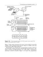
FX Series Programmable Controllers
Introduction 1
1 Introduction
1
2 Wiring
3 Specifications
4 N:N network
5 Parallel link
6 Communication format (D8120)
7 Computer link
8 Commands (for computer link)
9 RS instruction
10
FX
2N
-232IF
11 Optional programming port
12 Diagnostics
A Further Information Manual List
B ASCII code Lists
FX Series Programmable Controllers
Introduction 1
FX communication
Introduction 1
1-1
1
1. Introduction
1.1 Communication Types
The FX Series supports the fllowing 5 types of communication.
1 ) N:N network
Data transfer with FX
2N
, FX
2NC
, FX
1N
, FX
1S
, FX
0N
programmable controllers can be per-
formed on the N:N basis. They can link data of a small-scale system if using this network.
For system configuration refer to subsection 1.2.1, specifications refer to chapter 3, wiring
refer to chapter 2, settings, the number of transferred data and example program refer to
chapter 4,diagnostics refer to chapter 12.
2 ) Parallel link
Data transfer with FX
2N
, FX
2NC
, FX
1N
, FX and FX
2C
programmable controllers can be per-
formed on a 1:1 basis for 100 auxiliary relays and 10 data registers. With FX
1S
and FX
0N
data
transfer is performed for 50 auxiliary relays and 10 data registers.
For a system configuration refer to Subsection 1.2.2, specifications refer to chapter 3, wiring
refer to chapter 2, the setting and example program refer to chapter 5, diagnostics refer to
chapter 12.
3 ) Computer link (Data transfer using dedicated protocol)
Data transfer with RS485 (422) units can be performed on a 1:n (16) basis using the dedi-
cated protocol.
For system configuration refer to subsection 1.2.3, specifications refer to chapter 3, wiring
refer to chapter 2, setting of communication format refer to chapter 6, dedicated protocol
refer to chapter 7 & 8, diagnostics refer to chapter 12.
4 ) No protocol communication (Data transfer using RS instruction)
Data communication with a diversified RS232C unit including personal computers, bar code
readers and printers can be performed using no protocol communications.
This communication uses RS instruction’s or an FX
2N
-232IF special function block.
For system configuration refer to subsection 1.2.3, specifications refer to chapter 3, wiring
refer to chapter 2, setting of communication format, RS instruction and example program
refer to chapter 6 and 9, diagnostics refer to chapter 12.
When using the RS instruction, for setting the communication format refer to chapter 6, for
the RS instruction and example program please refer to chapter 9. Or when using an FX
2N
-
232IF, for setting and example program please refer to chapter 10.
5 ) Optional programming port
The port can support a programming protocol, if connected to an FX
2N
-232-BD, FX
0N
-32ADP,
FX
1N
-232-BD, FX
2N
-422-BD and FX
1N
-422-BD for FX
2N
, FX
2NC
, FX
1N
, FX
1S
Series program-
mable controller.
For notes on use, refer to chapter 11, diagnostics refer to chapter 12.
FX communication
Introduction 1
1-2
1.2 System Configuration
For programming protocol refer to chapter 11.
1.2.1 N:N Network
1.2.2 Parallel Link
1 ) FX
2N
, FX
2NC
(Shielded twisted-pair cable)
*1 When including FX
2N
-485-BD in system configuration, total extension distance max 50m.
2 ) FX
1N
(Shielded twisted-pair cable)
*2 When including FX
1N
-485-BD in system configuration, total extension distance max 50m.
3 ) FX
1S
(Shielded twisted-pair cable)
*3 When including FX
1N
-485-BD in system configuration, total extension distance max 50m.
4 ) FX
0N
(Shielded twisted-pair cable)
,
Using interface Extension distance
FX
2N
FX
2N
-485-BD Max. 50 m
FX
2N
-CNV-BD + FX
0N
-485ADP
Max. 500 m
*1
FX
2NC
FX
0N
-485ADP
,
Using interface Extension distance
FX
1N
FX
1N
-485-BD Max. 50 m
FX
1N
-CNV-BD + FX
0N
-485ADP
Max. 500 m
*2
,
Using interface Extension distance
FX
1s
FX
1N
-485-BD Max. 50 m
FX
1N
-CNV-BD + FX
0N
-485ADP
Max. 500 m
*3
,
Using interface Extension distance
FX
0N
FX
0N
-485ADP Max. 500 m
FX
2N
FX
0N
,
FX
2NC
FX
2N
FX
2N
-485-BD
FX
0N
-485ADP
FX
0N
-485ADP
FX
2N
-CNV-BD
When not using FX
2N
-485-BD or FX
1N
-485-BD in the system, total extension distance Max. 500m.
(Use : Max. 50m)
Total station of this network is Max. 8 stations.
FX
1S
,
FX
1N
FX
1N
-485-BD
FX
1S
,
FX
1N
FX
0N
-485ADP
FX
1N
-CNV-BD
① ②
FX communication
Introduction 1
1-3
1
5 ) FX, FX
2C
(Shielded twisted-pair cable and glassfiber cable)
Note;
Parallel link is possible between the same series PLC’s, or between other series in the
same group. However, parallel link between each group cannot be achieved.
Group’s are separated as follows.
1.2.3 Computer Link
1 ) Use RS485
2 ) Use RS232C
,
Using interface Extension distance
FX
2
, FX
2C
FX
2
-40AW (Shielded twisted-pair cable) Max. 10 m
FX
2
-40AP (Glassfiber cable) Max. 50 m
Group No. Series
Group 1 FX
2N
, FX
2NC
Group 2 FX
1N
Group 3 FX
1S
Group 4 FX
0N
Group 5 FX, FX
2C
FX
0N
-485ADP
FX
2
,
FX
2C
Computer
FX-485ADP
FX
2N
+ FX
2N
-485-BD,
FX
1S
+ FX
1N
-485-BD,
FX
1N
+ FX
1N
-485-BD
A series PLC + A
(1S)
J71UC24
When not using FX
2N
-485-BD or FX
1N
-485-BD in the system, total extension distance is
Max. 500m. (Use : Max. 50m)
Total station of this network is Max. 16 stations.
RS232C
RS485(422)
FX-485PC-IF
FX
0N
, FX
2NC
,
FX
2N
+ FX
2N
-CNV-BD,
FX
1S
+ FX
1N
-CNV-BD,
FX
1N
+ FX
1N
-CNV-BD
Computer
Total extension distance is 15m.
FX
2N
: FX
2N
-232-BD,
FX
2N
-CNV-BD + FX
0N
-232ADP
FX
2NC
, FX
0N
: FX
0N
-232ADP
FX
1N
, FX
1S
: FX
1N
-232-BD,
FX
1N
-CNV-BD + FX
0N
-232ADP
FX
2
, FX
2C
: FX-232ADP
FX communication
Introduction 1
1-4
1.2.4 No Protocol Communication
*1 RS485/RS232C signal convertor becomes necessary for a case of RS485 interface for com-
puter connection.
*2 When using FX
1N
-485-BD, FX
2N
-485-BD in system, total extension distance max 50m.
But, RS485/RS232C signal convertor become necessary for a case of RS232C interface for
computer connection.
*3 This system configuration can achieve full-duplex communication or the half-duplex communi-
cation.
*4 This system configuration achieve only half-duplex communication.
1.3 Supporting Function and Version
Items
FX
2N
,
FX
2NC
FX
1N
, FX
1S
FX
0N
FX, FX
2C
N:N network
All versions
All versions
V2.00 or more No sport
Parallel link All versions All versions
Computer link V1.20 or more V3.30 or more
No protocol
communication
Use RS instruction All versions V3.00 or more
Use FX
2N
-232IF
Not supported.
FX
2N
+
FX
2N
-CNV-BD
FX, FX
2C
FX
2N
+
FX
2N
-232-BD
FX
0N
-232ADP
RS232C
FX
2N
+ FX
2N
-CNV-BD
FX
1N
+ FX
1N
-CNV-BD
FX
1S
+ FX
1N
-CNV-BD
FX
0N
, FX
2NC
FX
2N
+ FX
2N
-485-BD
FX-232ADP
RS485(422)
FX
0N
-485ADP
Max 15m *1
Max 500m *2
*3
*4
*3
FX
0N
FX
1N
+
FX
1N
-CNV-BD
FX
1S
+
FX
1N
-CNV-BD
FX
0N
-232ADP
*4
*4 *3
Personal computer
Bar code reader
Printer
FX
2NC
FX
0N
-232ADP
*3
FX
1N
+ FX
1N
-485-BD
FX
1S
+ FX
1N
-485-BD
*4
FX
1N
+
FX
1N
-232-BD
FX
1S
+
FX
1N
-232-BD
*4
FX
2N
, FX
1N
,
FX
2NC
+ FX
2NC
-CNV-IF
FX
2N
-232IF
FX Series Programmable Controllers
Wiring 2
1 Introduction
2 Wiring
2
3 Specifications
4 N:N network
5 Parallel link
6 Communication format (D8120)
7 Computer link
8 Commands (for computer link)
9 RS instruction
10
FX
2N
-232IF
11 Optional programming port
12 Diagnostics
A Further Information Manual List
B ASCII code Lists
FX Series Programmable Controllers
Wiring 2
FX communication
Wiring 2
2-1
2
2. Wiring
For the terminal layout when using a communication unit, refer to the individual units manual.
2.1 Caution
2.1.1 Common
2.1.2 FX
2N
-485-BD
1 )This system is designed to read and write data (forced on/off) while the programmable con-
troller is running.
If abnormal data is written into the programmable controller, due to effects of noise, the pro-
grammable controller may malfunction and cause machine trouble or an accident. There-
fore, observe the following cautions.
• Do not lay signal cables near high voltage power cables or put them in the same trunking
duct.
Otherwise effects of noise or surge induction are likely to take place. Keep a safe dis-
tance of more than 100 mm from these wires.
• Ground the shield wire or shield of a shielded cable at one point on the programmable
controller. Do not, however, ground at the same point as high voltage lines.
2 )Cut off phases of power source externally, before installation or wiring work in order to avoid
electric shock or damage of product.
3 )Replace the provided terminal cover before supplying power and operating the unit after
installation or wiring work in order to avoid electric shock.
6mm
To connect the RS485(422) unit, use a shielded twist-pair cable. The cable model must be
AWG 26 to 16, and the maximum tightening torque must be 0.6 N
m (6 kgf
cm). If a cable other
than the AWG 26 to 16 is used, normal communication cannot be assured because the termi-
nal may be imperfectly contacted. It is recommended to insert a cable integrated by a crimping
tool into the terminal.
FX communication
Wiring 2
2-2
2.1.3 FX
0N
-485ADP
2.1.4 FX
2
-40AW
1 ) The terminal screws for the terminal block of the FX
2
-40AW are M3.5 screws and therefore
the crimp style terminal (see drawing) suitable for use with these screws should be fitted to
the cable for wiring.
2 ) The terminal tightening torque is 0.5 to 0.8 N
⋅
m (5 to 8 kgf
⋅
cm), tighten securely to avoid mal-
function.
For M3
6.2mm
(0.24 inches)
or less
6.2mm
(0.24 inches)
or less
For M3
1 ) The terminal screws of the FX
(0N)
-485ADP are M3 screws and therefore the crimp style ter-
minal (see drawing) suitable for use with these screws should be fitted to the cable for wir-
ing.
2 ) The terminal tightening torque is 0.5 to 0.8 N
⋅
m(5 to 8 kgf
⋅
cm), tighten securely to avoid
malfunction.
For M3.5
6.8mm
(0.27 inches)
or less
6.8mm
(0.27 inches)
or less
For M3.5
FX communication
Wiring 2
2-3
2
2.2 Using RS232C Interface
Below is a typical wiring example. Please wire similar to the following pin name, when a pin num-
ber on the side of a counterpart machine differs.
2.2.1 Using RS Instruction or Computer Link
1 ) Terminal specification device
Note;
When using ER and DR signals, please also check if RS and CS signals are needed according to
the RS232C device specifications.
2 ) Modem specification device
Note;
The FX
0N
-232ADP does not monitor the CD pin (pin8).
3 ) Computer link
Please refer to 2.2.1 1) for wiring.
Programmable Controller Side
Signal
name
FG
RD (RXD)
SD (TXD)
ER (DTR)
SG (GND)
DR (DSR)
FX
2N
-
232-BD
FX
1N
-
232-BD
FX0N-
232ADP
FX-
232ADP
- 1
32
23
204
75
66
RS-232C Device Side
Signal
name
FG
RD (RXD)
SD (TXD)
RS RTS)
SG (GND)
CS (CTS)
Uses CS, RS
-
2
3
7
5
8
9-pin
D-SUB
Signal
name
Uses DR, ER
FG
RD (RXD)
SD (TXD)
ER (DTR)
SG (GND)
DR (DSR)
25-pin
D-SUB
9-pin
D-SUB
25-pin
D-SUB
1
3
2
4
7
5
-
2
3
4
5
6
1
3
2
20
7
6
Programmable Controller Side
Signal
name
FG
RD (RXD)
SD (TXD)
ER (DTR)
SG (GND)
DR (DSR)
FX
2N
-
232-BD
FX
1
N
-
232-BD
FX
0N
-
232ADP
FX-
232ADP
- 1
32
23
204
75
66
RS-232C Device Side
Signal
name
FG
RD (RXD)
SD (TXD)
RS RTS)
SG (GND)
CS (CTS)
Uses CS, RS
-
2
3
7
5
8
9-pin
D-SUB
Signal
name
Uses DR, ER
FG
RD (RXD)
SD (TXD)
ER (DTR)
SG (GND)
DR (DSR)
25-pin
D-SUB
9-pin
D-SUB
25-pin
D-SUB
1
3
2
4
7
5
-
2
3
4
5
6
1
3
2
20
7
6
CD (DCD) 1 - 8 CD (DCD) 1 FG8 1 8