ST hê THỐNG lái TRÊN NISSAN VERSA SEDAN 2012
Bạn đang xem bản rút gọn của tài liệu. Xem và tải ngay bản đầy đủ của tài liệu tại đây (606.98 KB, 17 trang )
ST-1
STEERING
C
D
E
F
H
I
J
K
L
M
SECTION ST
A
B
ST
N
O
P
CONTENTS
STEERING SYSTEM
PRECAUTION 2
PRECAUTIONS 2
Precaution for Supplemental Restraint System
(SRS) "AIR BAG" and "SEAT BELT PRE-TEN-
SIONER"
2
Service Notice or Precautions for Steering System
2
PREPARATION 3
PREPARATION 3
Special Service Tools 3
Commercial Service Tools 3
BASIC INSPECTION 4
STEERING WHEEL 4
Inspection 4
SYMPTOM DIAGNOSIS 6
NOISE, VIBRATION AND HARSHNESS
(NVH) TROUBLESHOOTING
6
NVH Troubleshooting Chart 6
REMOVAL AND INSTALLATION 7
STEERING WHEEL 7
Exploded View 7
Removal and Installation 7
STEERING COLUMN 8
Exploded View 8
Removal and Installation 8
Inspection 9
STEERING SHAFT 11
Exploded View 11
Removal and Installation 11
Inspection 12
STEERING GEAR AND LINKAGE 13
Exploded View 13
Removal and Installation 14
Inspection 14
SERVICE DATA AND SPECIFICATIONS
(SDS) 16
SERVICE DATA AND SPECIFICATIONS
(SDS)
16
General Specifications 16
Steering Wheel Axial End Play and Play 16
Steering Wheel Turning Force 16
Steering Angle 16
Steering Column Operating Range 16
Rack Stroke 17
Ball Joint Swing Force 17
Ball Joint Axial End Play 17
Inner Socket Length 17
Revision: July 2011 2012 Versa Sedan
ST-2
< PRECAUTION >
PRECAUTIONS
PRECAUTION
PRECAUTIONS
Precaution for Supplemental Restraint System (SRS) "AIR BAG" and "SEAT BELT
PRE-TENSIONER"
INFOID:0000000007207826
The Supplemental Restraint System such as “AIR BAG” and “SEAT BELT PRE-TENSIONER”, used along
with a front seat belt, helps to reduce the risk or severity of injury to the driver and front passenger for certain
types of collision. This system includes seat belt switch inputs and dual stage front air bag modules. The SRS
system uses the seat belt switches to determine the front air bag deployment, and may only deploy one front
air bag, depending on the severity of a collision and whether the front occupants are belted or unbelted.
Information necessary to service the system safely is included in the SR and SB section of this Service Man-
ual.
WARNING:
• To avoid rendering the SRS inoperative, which could increase the risk of personal injury or death in
the event of a collision which would result in air bag inflation, all maintenance must be performed by
an authorized NISSAN/INFINITI dealer.
• Improper maintenance, including incorrect removal and installation of the SRS, can lead to personal
injury caused by unintentional activation of the system. For removal of Spiral Cable and Air Bag
Module, see the SR section.
• Do not use electrical test equipment on any circuit related to the SRS unless instructed to in this
Service Manual. SRS wiring harnesses can be identified by yellow and/or orange harnesses or har-
ness connectors.
PRECAUTIONS WHEN USING POWER TOOLS (AIR OR ELECTRIC) AND HAMMERS
WARNING:
• When working near the Airbag Diagnosis Sensor Unit or other Airbag System sensors with the Igni-
tion ON or engine running, DO NOT use air or electric power tools or strike near the sensor(s) with a
hammer. Heavy vibration could activate the sensor(s) and deploy the air bag(s), possibly causing
serious injury.
• When using air or electric power tools or hammers, always switch the Ignition OFF, disconnect the
battery, and wait at least 3 minutes before performing any service.
Service Notice or Precautions for Steering System INFOID:0000000007207828
• In case of removing steering gear assembly, make the final tightening with grounded and unloaded vehicle
condition, and then check wheel alignment.
• Observe the following precautions when disassembling.
- Before disassembly, thoroughly clean the outside of the unit.
- Disassembly should be done in a clean work area. It is important to prevent the internal parts from becoming
contaminated by dirt or other foreign matter.
- For easier and proper assembly, place disassembled parts in order on a parts rack.
- Use nylon cloth or paper towels to clean the parts; common shop rags can leave lint that might interfere with
their operation.
- Never reuse non-reusable parts.
- Before assembling, apply the specified grease to the directed parts.
Revision: July 2011 2012 Versa Sedan
PREPARATION
ST-3
< PREPARATION >
C
D
E
F
H
I
J
K
L
M
A
B
ST
N
O
P
PREPARATION
PREPARATION
Special Service Tools INFOID:0000000007207829
The actual shapes of Kent-Moore tools may differ from those of special tools illustrated here.
Commercial Service Tools INFOID:0000000007207830
Tool number
(Kent-Moore No.)
Tool name
Description
ST27180001
(J-25726-A)
Steering wheel puller
Removing steering wheel
ST3127S000
(J-25765-A)
Preload gauge
Inspecting rotating torque for steering column
assembly and pinion assembly
KV40107300
(—)
Boot Band crimping tool
Installing boot bands
—
(J-44372)
Pull gauge
Measuring steering wheel turning force and
ball joint swinging force
S-NT544
ZZA0806D
ZZA1229D
LST024
Tool name Description
Ball joint remover Remove steering outer socket
S-NT146
Revision: July 2011 2012 Versa Sedan
ST-4
< BASIC INSPECTION >
STEERING WHEEL
BASIC INSPECTION
STEERING WHEEL
Inspection INFOID:0000000007207831
CHECKING CONDITION OF INSTALLATION
• Check installation conditions of steering gear assembly, front suspension assembly, axle and steering col-
umn assembly.
• Check if movement exists when steering wheel is moved up and down, to the left and right and to the axial
direction.
• Check steering gear assembly mounting bolts and nuts for looseness. Refer to ST-14, "
Removal and Instal-
lation".
CHECKING STEERING WHEEL PLAY
1. Turn steering wheel so that front wheels come to the straight-ahead position. Start engine and lightly turn
steering wheel to the left and right until front wheels start to move. Measure steering wheel movement on
the outer circumference.
2. When the measurement value is outside the standard value, check backlash for each joint of steering col-
umn assembly and installation condition of steering gear assembly.
NEUTRAL POSITION STEERING WHEEL
1. Check that steering gear assembly, steering column assembly and steering wheel are installed in the cor-
rect position.
2. Check wheel alignment within specification. Refer to FSU-5, "
Inspection and Adjustment".
3. Set vehicle to the straight-ahead position and confirm steering wheel is in the neutral position.
• Loosen outer socket lock nut and turn inner socket to left and right equally to make fine adjustments if
steering wheel is not in the neutral position.
CAUTION:
If the adjustment is performed by using the inner socket, check wheel alignment after the adjust-
ment. Refer to FSU-5, "
Inspection and Adjustment".
STEERING WHEEL TURNING FORCE
1. Park vehicle on a level and dry surface, set parking brake.
2. Tires need to be inflated normal pressure. Refer to WT-45, "
Tire Air Pressure".
3. Start engine.
4. Check steering wheel turning force when steering wheel has
been turned 360° from neutral position using Tool as shown.
FRONT WHEEL TURNING ANGLE
1. Perform toe-in inspection. Refer to FSU-5, "Inspection and Adjustment".
Steering wheel axial end play
and play
Refer to ST-16, "
Steering Wheel Axial End Play and Play".
Steering wheel axial end play
and play
Refer to ST-16, "
Steering Wheel Axial End Play and Play".
Tool number : — (J-44372)
Steering wheel turning
force
: Refer to ST-16, "Steering
Wheel Turning Force".
SGIA1523J
Revision: July 2011 2012 Versa Sedan
STEERING WHEEL
ST-5
< BASIC INSPECTION >
C
D
E
F
H
I
J
K
L
M
A
B
ST
N
O
P
CAUTION:
Perform front wheel turning angle inspection, after toe-in inspection.
2. Place front wheels on turning radius gauges and rear wheels on
stands, so that vehicle can be level.
3. Check the maximum inner and outer wheel turning angles for LH
and RH road wheels.
• With the engine at idle, turn steering wheel from full left stop to
full right stop and measure the turning angles.
• Check the following items when turning angle is out of the standard.
- Check rack stroke (L).
- Disassemble steering gear assembly to check the cause that
rack stroke is outside of the standard.
• Steering angles are not adjustable. Check steering gear
assembly, steering column assembly and front suspension
components for wear or damage if any of the turning angles
are different from the specified value. Replace any of them, if
any non-standard condition exists.
FAA0016D
Inner wheel (Angle: A) : Refer to ST-16, "Steering
Angle".
Outer wheel (Angle: B) : Refer to ST-16, "
Steering
Angle".
SGIA0055E
Rack stroke (L) : Refer to ST-17, "Rack Stroke".
JSGIA0272ZZ
Revision: July 2011 2012 Versa Sedan
ST-6
< SYMPTOM DIAGNOSIS >
NOISE, VIBRATION AND HARSHNESS (NVH) TROUBLESHOOTING
SYMPTOM DIAGNOSIS
NOISE, VIBRATION AND HARSHNESS (NVH) TROUBLESHOOTING
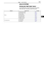
NVH Troubleshooting Chart INFOID:0000000007207832
Use the chart below to find the cause of the symptom. If necessary, repair or replace these parts.
×: Applicable
Reference page
ST-14, "Inspection"
ST-14, "Inspection"
ST-14, "Inspection"
ST-4, "Inspection"
ST-4, "Inspection"
ST-8, "Removal and Installation"
ST-13, "Exploded View"
ST-9, "Inspection"
ST-8, "Exploded View"
ST-13, "Exploded View"
FAX-6, "NVH Troubleshooting Chart"
RAX-4, "NVH Troubleshooting Chart"
FSU-4, "NVH Troubleshooting Chart"
RSU-3, "NVH Troubleshooting Chart"
WT-36, "NVH Troubleshooting Chart"
WT-36, "NVH Troubleshooting Chart"
FAX-6, "NVH Troubleshooting Chart"
BR-7, "NVH Troubleshooting Chart"
Possible cause and SUSPECTED PARTS
Outer/inner socket ball joint swinging torque
Outer/inner socket ball joint rotating torque
Outer/inner socket ball joint end play
Steering wheel play
Improper steering wheel
Improper installation or looseness of tilt lock lever
Mounting looseness
Steering column deformation or damage
Improper installation or looseness of steering column
Steering linkage looseness
AXLE and SUSPENSION
TIRE
ROAD WHEEL
DRIVE SHAFT
BRAKE
Symptom
Noise ×××× ×× × ××××
Shake ××× × ××××
Vibration ××××× × × ×
Shimmy ×× ×××××
Shudder ×× ×××××
Revision: July 2011 2012 Versa Sedan
STEERING WHEEL
ST-7
< REMOVAL AND INSTALLATION >
C
D
E
F
H
I
J
K
L
M
A
B
ST
N
O
P
REMOVAL AND INSTALLATION
STEERING WHEEL
Exploded View INFOID:0000000007207834
Removal and Installation INFOID:0000000007207835
REMOVAL
NOTE:
When reconnecting spiral cable, secure cable with a tape so that case and rotating part stay aligned. This will
omit neutral position alignment procedure during spiral cable installation.
1. Set vehicle to the straight-ahead position.
2. Remove driver air bag module. Refer to SR-4, "
Removal and Installation".
3. Remove steering wheel lock nut after steering is locked.
4. Remove steering wheel using Tool (A).
INSTALLATION
Installation is in the reverse order of removal.
• Check the spiral cable neutral position after replacing or rotating spiral cable. Refer to SR-7, "
Removal and
Installation".
CAUTION:
Do not twist spiral cable excessively after it becomes tight. (Twisting may cause the cable to be torn
off.)
• Do not reuse steering wheel lock nut.
1. Steering wheel
JSGIA0704GB
Tool number : ST27180001 (J-25726-A)
JSGIA0654ZZ
Revision: July 2011 2012 Versa Sedan
ST-8
< REMOVAL AND INSTALLATION >
STEERING COLUMN
STEERING COLUMN
Exploded View INFOID:0000000007207836
Removal and Installation INFOID:0000000007207837
REMOVAL
CAUTION:
• Keep steering column assembly away from magnetic sources.
• Do not disassemble steering column assembly.
• While removing the steering column assembly, do not move the steering gear.
• When removing the steering column assembly, be careful not to allow the intermediate shaft to turn.
1. Set vehicle to the straight-ahead position.
2. Place the steering column tilt to the lowest selection.
3. Remove instrument lower panel LH. Refer to IP-20, "
Removal and Installation".
4. Remove driver air bag module. Refer to SR-4, "
Removal and Installation".
5. Remove steering wheel. Refer to ST-7, "
Exploded View".
6. Remove steering column cover. Refer to IP-15, "
Removal and Installation".
7. Remove spiral cable. Refer to SR-7, "
Removal and Installation".
8. Remove combination switch. Refer to EXL-85, "
Exploded View"
9. Remove the cluster lid A. Refer to IP-19, "Removal and Installation"
10. Disconnect the switch harness connectors.
11. Remove the key cylinder only if the steering column is being replaced. Refer to TM-232, "
Removal and
Installation".
12. Place the steering column tilt to the middle selection.
CAUTION:
Do not change the position of the tilt mechanism until the steerign column is reinstalled.
13. Loosen the steering shaft lower joint bolt.
14. Remove the intermediate shaft upper bolt and separate intermediate shaft from steering column assem-
bly. Refer to ST-11, "
Removal and Installation".
CAUTION:
• Place a matching mark on both intermediate shaft and steering column assembly before remov-
ing intermediate shaft.
1. Steering column assembly 2. Clamp
JPGIA0110GB
Revision: July 2011 2012 Versa Sedan
STEERING COLUMN
ST-9
< REMOVAL AND INSTALLATION >
C
D
E
F
H
I
J
K
L
M
A
B
ST
N
O
P
• When removing intermediate shaft, never insert any tool into the yoke groove to pull out the
intermediate shaft or damage could occur. Replace intermediate shaft with a new one if dam-
aged.
15. Disconnect EPS control unit harness connectors.
16. Remove steering column assembly.
17. Remove EPS control unit from steering column assembly. Refer to STC-40, "
Removal and Installation".
18. Remove clamp from steering column assembly.
19. Perform inspection after removal. Refer to ST-9, "
Inspection".
INSTALLATION
CAUTION:
• Do not impact on the axis when removing steering column assembly.
• When installing the steering column cover, check that the vehicle harness is not stuck in the cover.
Installation is in the reverse order of removal.
• For intermediate shaft bolt direction, refer to ST-11, "
Exploded View".
• When connecting intermediate shaft upper side (1) and column
shaft, make sure the bolt is securely seated in groove (A) of col-
umn shaft before final tightening.
• After installing steering column assembly, perform self-diagnosis
with CONSULT to ensure correct operation. Refer to STC-9,
"CONSULT Function".
• Perform inspection after installation. Refer to ST-9, "
Inspection".
Inspection INFOID:0000000007207838
INSPECTION AFTER REMOVAL
• Check each part of steering column assembly for damage or other malfunctions. Replace if there are any
abnormal conditions.
• Measure steering column rotating torque using Tool (A). Replace
steering column assembly if the rotating torque is outside the stan-
dard.
• Measure the steering column length (L) as shown in the figure, if
vehicle has been involved in a minor collision. Replace steering
column assembly (with motor, reduction gear, sensor) if (L) is out-
side the standard.
INSPECTION AFTER INSTALLATION
• Check each part of steering column assembly for damage or other malfunctions. Replace if there are any
abnormal conditions.
SGIA1295E
Tool number : — )
Rotating torque : Refer to ST-16, "
Steering Column Op-
erating Range".
JPGIA0085ZZ
Steering column length
(L)
: Refer to ST-16, "Steering
Column Operating Range".
JPGIA0111ZZ
Revision: July 2011 2012 Versa Sedan
ST-10
< REMOVAL AND INSTALLATION >
STEERING COLUMN
• Check the steering wheel play, neutral position steering wheel, steering wheel turning force, and front wheel
turning angle. Refer to ST-4, "
Inspection".
• Check tilt mechanism operating range (T) as shown.
Tilt operating
range (T)
: Refer to ST-16, "
Steering Column Op-
erating Range".
JPGIA0043ZZ
Revision: July 2011 2012 Versa Sedan
STEERING SHAFT
ST-11
< REMOVAL AND INSTALLATION >
C
D
E
F
H
I
J
K
L
M
A
B
ST
N
O
P
STEERING SHAFT
Exploded View INFOID:0000000007207839
Removal and Installation INFOID:0000000007207840
REMOVAL
CAUTION:
Spiral cable may be cut if steering wheel turns while separating steering column assembly and steer-
ing gear assembly. Be sure to secure steering wheel using string to avoid turning.
1. Set vehicle to the straight-ahead position.
2. Place the steering column tilt to the middle selection.
3. Remove instrument lower panel LH. Refer to IP-20, "
Removal and Installation".
4. Loosen lower joint upper bolt.
5. Remove lower joint lower bolt and separate lower joint from steering gear assembly.
CAUTION:
• Place a matching mark on both lower joint and steering gear assembly before removing lower
joint.
• When removing lower joint, never insert any tool into the yoke groove to pull out the lower joint.
Replace the lower joint with a new one if damaged.
6. Remove lower joint from intermediate shaft.
7. Remove intermediate shaft bolt (steering column side), and remove intermediate shaft from steering col-
umn assembly.
CAUTION:
• Place a matching mark on both intermediate shaft and steering column assembly before remov-
ing intermediate shaft.
• When removing intermediate shaft, never insert any tool into the yoke groove to pull out the
intermediate shaft or damage could occur. Replace intermediate shaft with a new one if dam-
aged.
INSTALLATION
CAUTION:
Spiral cable may be cut if steering wheel turns while separating steering column assembly and steer-
ing gear assembly. Be sure to secure steering wheel using string to avoid turning.
Installation is in the reverse order of removal.
• Before installation, check that the tilt position is at the middle level.
• For intermediate shaft bolt, and lower joint bolt direction, refer to ST-11, "
Exploded View".
1. Lower joint 2. Intermediate shaft 3. Steering column assembly
JPGIA0112GB
Revision: July 2011 2012 Versa Sedan
ST-12
< REMOVAL AND INSTALLATION >
STEERING SHAFT
• To install align the steering gear guide protrusion (A) with the
groove of lower joint (1), make sure the bolt is securely seated in
groove (B) of steering gear before final tightening.
CAUTION:
If a guide protrusion is not included, align with the matching
mark placed at the removal step.
• When tightening lower joint bolt (steering gear assembly side),
temporarily tighten it and make sure there is no sticking or galling
before final tightening.
• When connecting intermediate shaft upper side (1) and column
shaft, make sure the bolt is securely seated in groove (A) of col-
umn shaft before final tightening.
• Perform inspection after installation. Refer to ST-12, "
Inspection".
Inspection INFOID:0000000007207841
INSPECTION AFTER REMOVAL
• Check each part of lower joint for damage or other malfunctions. Replace if there are any abnormal condi-
tions.
• Check each part of intermediate shaft for damage or other malfunctions. Replace if there are any abnormal
conditions.
INSPECTION AFTER INSTALLATION
• Check each part of lower joint for damage or other malfunctions. Replace if there are any abnormal condi-
tions.
• Check each part of intermediate shaft for damage or other malfunctions. Replace if there are any abnormal
conditions.
• Rotate steering wheel to check for decentered condition, binding, noise, or excessive steering effort.
• Check the steering wheel play, neutral position steering wheel, steering wheel turning force, and front wheel
turning angle.
- Steering wheel play: Refer to ST-4, "
Inspection".
- Neutral position steering wheel, steering wheel turning force, and front wheel turning angle: Refer to ST-4,
"Inspection".
JPGIA0041ZZ
SGIA1295E
Revision: July 2011 2012 Versa Sedan
STEERING GEAR AND LINKAGE
ST-13
< REMOVAL AND INSTALLATION >
C
D
E
F
H
I
J
K
L
M
A
B
ST
N
O
P
STEERING GEAR AND LINKAGE
Exploded View INFOID:0000000007207842
REMOVAL AND INSTALLATION
DISASSEMBLY AND ASSEMBLY
1. Guide 2. Cowl seal 3. Steering gear assembly
4. Front suspension member
: Vehicle front
AWGIA0193GB
1. Joint cover 2. Gear housing assembly 3. Inner socket
4. Boot clamp (large diameter) 5. Boot 6. Boot clamp (small diameter)
7. Outer socket
ALGIA0098GB
Revision: July 2011 2012 Versa Sedan
ST-14
< REMOVAL AND INSTALLATION >
STEERING GEAR AND LINKAGE
Removal and Installation
INFOID:0000000007207843
REMOVAL
1. Set vehicle to the straight-ahead position.
2. Place the steering column tilt to middle selection.
3. Loosen lower joint upper bolt.
4. Remove lower joint lower bolt. Refer to ST-8, "
Removal and Installation".
CAUTION:
• Spiral cable may be cut if steering wheel turns while separating steering column assembly and
steering gear assembly. Always secure the steering wheel using string to avoid turning.
• Place a matching mark on both lower joint and steering gear assembly before removing lower
joint.
• When removing lower joint, never place any tool into the yoke groove to pull out the lower joint.
Replace the lower joint with a new one if damaged.
5. Remove the wheel and tire assemblies using power tool.
6. Remove steering outer socket from steering knuckle using a
suitable tool.
7. Support front suspension member with a suitable jack.
8. Remove front suspension member bolts. Refer to FSU-15,
"Removal and Installation".
9. Remove the bolts and nuts of steering gear assembly.
10. Separate cowl seal from vehicle.
11. Lower the suitable jack to the position where the steering gear
assembly can be removed.
CAUTION:
Secure front suspension member to a jack.
12. Remove guide from pinion assembly.
13. Remove cowl seal from steering gear assembly.
INSTALLATION
Installation is in the reverse order of removal.
CAUTION:
• Spiral cable may be cut if steering wheel turns while separating steering column assembly and steer-
ing gear assembly. Always secure the steering wheel using string to avoid turning.
• The guide protrusion is not required to be reinstalled.
• Before installation, check that the steering column tilt position is at the middle level.
• Clean mating surface on the body side of cowl seal when installing steering gear assembly.
• Perform final tightening of nuts and bolts on each part under unladen conditions with tires on level ground
when removing steering gear assembly. Check wheel alignment. Refer to FSU-5, "
Inspection and Adjust-
ment".
• Rotate steering wheel to check that the spiral cable is centered, binding, noise or excessive steering effort.
• Do not reuse steering outer socket nut and cowl seal.
• Perform inspection after installation. Refer to ST-14, "
Inspection".
Inspection INFOID:0000000007207845
INSPECTION AFTER DISASSEMBLY
Boot
• Check boot for cracks, and replace it if damage exists.
Gear Housing Assembly
• Check gear housing assembly for damage and scratches (inner wall). Replace if there are any abnormal
conditions.
Outer Socket and Inner Socket
• Check the following items and replace the component if it does not meet the standard.
BALL JOINT SWINGING FORCE
SGIA0184J
Revision: July 2011 2012 Versa Sedan
STEERING GEAR AND LINKAGE
ST-15
< REMOVAL AND INSTALLATION >
C
D
E
F
H
I
J
K
L
M
A
B
ST
N
O
P
• Hook a Tool at the point shown and pull the spring balance. Make
sure that the Tool reads the specified value when ball stud and
inner socket start to move. Replace outer socket and inner socket
if they are outside the standard.
BALL JOINT AXIAL END PLAY
• Apply an axial load of 490 N (50 kg, 110 lb) to ball stud. Using a
dial gauge, measure amount of stud movement, and then make
sure that the value is within the following specified range. Replace
outer socket (1) and inner socket (2) if the measured value is out-
side the standard.
INSPECTION AFTER INSTALLATION
• Check if steering wheel turns smoothly when it is turned several times throughout the full steering range.
• Check the steering wheel play, neutral position steering wheel, steering wheel turning force, and front wheel
turning angle.
- Steering wheel play: Refer to ST-4, "
Inspection".
- Neutral position steering wheel, steering wheel turning force, and front wheel turning angle: Refer to ST-4,
"Inspection".
Measuring point of outer socket (1) : Ball stud upper side (A)
Measuring point of inner socket (2) : Point (B)
Tool number : — (J-44372)
Swinging force : Refer to ST-17, "
Ball Joint Swing
Force".
Axial end play : Refer to ST-17, "
Ball Joint Axial End
Play".
JPGIA0188ZZ
JSGIA0109ZZ
Revision: July 2011 2012 Versa Sedan
ST-16
< SERVICE DATA AND SPECIFICATIONS (SDS)
SERVICE DATA AND SPECIFICATIONS (SDS)
SERVICE DATA AND SPECIFICATIONS (SDS)
SERVICE DATA AND SPECIFICATIONS (SDS)
General Specifications INFOID:0000000007207846
Steering Wheel Axial End Play and Play INFOID:0000000007207847
Unit: mm (in)
Steering Wheel Turning Force INFOID:0000000007207848
Unit: N (kg-f, lb-f)
Steering Angle INFOID:0000000007207849
Unit: Degree minute (Decimal degree)
Steering Column Operating Range INFOID:0000000007207850
*: For measuring position, refer to ST-9, "Inspection".
Steering gear model R24K
Item Standard
Steering wheel axial end play 0 (0)
Steering wheel play on the outer circumference 0 - 35 (0 - 1.38)
Item Standard
Steering wheel turning force 36 (3.7, 8.09) or less
Item Standard
Inner wheel (Angle A)
Minimum 34° 30′ (34.5°)
Nominal 37° 30′ (37.5°)
Maximum 38° 30′ (38.5°)
Outer wheel (Angle B) Nominal 32° 00′ (32.0°)
SGIA0055E
Item Standard
Tilt operating range
*
39.4 mm (1.551 in)
Rotating torque 0 – 2.1 N·m (0 – 0.21 kg-m, 0 – 2 in-lb)
Steering column length
*
477.9 mm (18.81 in)
Revision: July 2011 2012 Versa Sedan
SERVICE DATA AND SPECIFICATIONS (SDS)
ST-17
< SERVICE DATA AND SPECIFICATIONS (SDS)
C
D
E
F
H
I
J
K
L
M
A
B
ST
N
O
P
Rack Stroke INFOID:0000000007207851
Unit: mm (in)
Ball Joint Swing Force INFOID:0000000007207852
*: For measuring position, refer to ST-14, "Inspection".
Ball Joint Axial End Play INFOID:0000000007207853
Unit: mm (in)
Inner Socket Length INFOID:0000000007207854
Unit: mm (in)
Item Standard
Rack stroke neutral position (L) 64.6 (2.543)
JSGIA0272ZZ
Item Standard
Outer socket
Spring balance measurement
*
6.0 – 58 N (0.61 – 5.9 kg-f, 1.35 – 13.03 lb-f)
Inner socket
Spring balance measurement
*
3.5 – 34.7 N (0.36 – 3.5 kg-f, 0.79 – 7.8 lb-f)
Item Standard
Outer socket 0.5 (0.020) or less
Inner socket 0.2 (0.008 in) or less
Item Standard
Rack neutral position, dimension 67.3 (2.650)
Revision: July 2011 2012 Versa Sedan