Synthesis of nano al2o3 dispersion strengthened cu base composite materials by mechanochemical process
Bạn đang xem bản rút gọn của tài liệu. Xem và tải ngay bản đầy đủ của tài liệu tại đây (1.75 MB, 75 trang )
HANOI UNIVERSITY OF SCIENCE AND TECHNOLOGY
SCHOOL OF MATERIALS SCIENCE AND TECHNOLOGY
THESIS OF GRADUATION
Synthesis of nano Al
2
O
3
dispersion
strengthened - Cu base composite materials
by mechanochemical process
Student: Phung Anh Tuan
MSE-ATP-K52
Advisor: Dr. Nguyen Dang Thuy
Hanoi, June 2012
1
Table of contents
Preface 5
Chapter I: OVERVIEW 6
1.1 Composite materials 6
1.1.1 Definition 6
1.1.2 Class of composite materials 8
1.2 Metal matrix composites 9
1.2.1 Reinforcements 11
1.2.2 Matrix alloy systems 13
1.3 Partical-reinforced composites 14
1.3.1 Large-particle composites 14
1.3.2 Dispersion-strengthened composites 8
1.4 Bearing materials 19
1.4.1 Structure and properties and applications of bearing materials 20
1.4.2 Conventional bearing materials 22
1.5 Copper alumina composite 29
Chapter II: MECHANICAL ALLOYING 30
2.1 History 30
2.2 Milling 34
2.3 Mechanism of alloying 36
2.3.1. Ductile –Ductile components 38
2.3.2. Ductile – Brittle 39
2.3.3. Britle-Brittle component 40
Chapter III: EXPERIMENTAL PROCEDURE 41
3.1 Milling 41
3.2 Pressing 44
2
3.3 Sintering 45
Chapter IV: RESULTS AND DISCUSSION 48
4.1. Results after milling 48
4.2. Results after sintering 56
4.3. Porosity 58
4.4. Hardness 61
4.5. Microstructure 62
4.6. Experimental planning and process optimization 64
Chapter V: CONCLUSION AND SUGGESTION 71
5.1. Conclusions 71
5.2. Suggestions 71
References 72
3
List of figures
No
Titles
Pages
1.1
Schematic representations of the various geometrical and
spatial characteristics of particles of the dispersed phase
that may influence the properties of composites.
8
1.2
A classification scheme for the various composite types
discussed in this chapter.
9
1.3
Modulus of elasticity versus volume percent tungsten for a
composite of tungsten particles dispersed within a copper
matrix. Upper and lower bounds are according to
Equations 16.1 and 16.2; experimental data points are
included.
16
1.4
Photomicrograph of a WC–Co cemented carbide. Light
areas are the cobalt matrix; dark regions, the particles of
tungsten carbide.
17
1.5
Some bearings are made from copper alloys.
19
1.6
The popular designs for Engine bearing structure
25
2.1
Model 1-S attritor and arrangement of rotating arms on a
shaft in the attrition ball mill.
35
2.2
Ball-powder-ball collision of powder mixture during
mechanical alloying.
37
2.3
Scanning electron micrograph depicting the convoluted
lamellar structure obtained during milling of a ductile-
ductile component system (Ag-Cu).
39
2.4
Schematics of microstructure evolution during milling of a
ductile-brittle combination of powders. This is typical of an
oxide dispersion strengthened case
40
3.1
Milling chamber of the attritor.
42
3.2
The balls after milling process.
43
3.3
The synthesis process of materials.
44
3.4
Picture of compaction mold.
44
3.5
Picture of hydraulic pressing machine.
45
4
3.6
Sintering diagram of Cu-Al
2
O
3
46
3.7
Picture of Linn’s furnace for sintering.
46
4.1
SEM images form the initial sample mixture CuO-Cu-Al
and after milling with speed 620rpm during 15h.
49
4.2
Powder Diffractometer Siemens D5005.
49
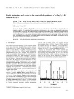
4.3
The X-ray diffraction diagram of original mixed powder
material samples, including Cu, CuO and Al powder.
51
4.4
The results of X-ray analysis of powder samples after 4
hours milling.
52
4.5
The results of X-ray analysis of powder samples after 6
hours milling.
53
4.6
The results of X-ray analysis of powder samples after 12
hours milling.
54
4.7
The X-ray diffraction diagram of mixed powder material
samples
55
4.8
The X-ray diffraction diagram of mixed powder material
samples, after 12 hours milling and sintering.
57
4.9
Schematic of porosity measurement instrument
59
4.10
SEM images samples Cu- Al
2
O
3
(wt.10%) after sintering at
700°C in 3h (X30.000)
63
List of tables
No
Titles
Pages
1.1
Properties of typical discontinuous reinforcements for
aluminium and magnesium reinforcements.
12
2.1
Important milestones in the development of mechanical
alloying.
33
4.1
Table of porosity of samples
60
4.2
Table of hardness of samples
61
4.3
Table of conditions of experiments
65
4.4
Table of factors
68
5
Preface
As the time elapsed, living standard is continuously increased. One of the
most important reasons for this is the developing in science and technology. The
requirement for the new materials is much debated in our social. It set new
challenges for the materials science and technology. In our country, there is a
potential market in every fields of the industry. The materials nowadays need to
have many unique properties. Moreover, the prices of synthesis have to be as low
as possible. Thus, scientists tend to research to find the simplest method to create
the best materials with a proper price. That’s a reason why I find interest in the
mechanical alloying-the simple method to produce alloys with many advantages.
Therefore, I have chosen the project namely “Synthesis of nano Al
2
O
3
dispersion
strengthened - Cu base composite materials by mechanochemical process”
In my project I will focus on composite base on Cu with Al
2
O
3
dispersion.
Cu-Al
2
O
3
composite is one of the newest bearing materials of engines. This
bearing system is developing in the world. However the synthesis method is keep
in secret.
I express my deep gratitude to Doctor Nguyen Dang Thuy who helped me to
find enthusiasm in researching, showed me how to think critically and work
effectively. He is not only my teacher but also my instructor in researching.
I send my true thankfulness to every laboratory in School of Materials
Science and Technology, Hanoi University of Science and Technology and all
technicians, teachers, professors in School of Materials Science and Technology
who have already helped me to complete this project.
And, thanks to other lovely members in my research group, who have worked
with me and helped me a lot.
6
Chapter I: OVERVIEW
1.1. COMPOSITE MATERIALS
1.1.1 Definition
Many of our modern technologies require materials with unusual
combinations of properties that cannot be met by the conventional metal alloys,
ceramics, and polymeric materials. This is especially true for materials that are
needed for aerospace, underwater, and transportation applications. For example,
aircraft engineers are increasingly searching for structural materials that have low
densities, are strong, stiff, and abrasion and impact resistant, and are not easily
corroded.This is a rather formidable combination of characteristics. Frequently,
strong materials are relatively dense; also, increasing the strength or stiffness
generally results in a decrease in impact strength.
Material property combinations and ranges have been, and are yet being,
extended by the development of composite materials. Generally speaking, a
composite is considered to be any multiphase material that exhibits a significant
proportion of the properties of both constituent phases such that a better
combination of properties is realized. According to this principle of combined
action, better property combinations are fashioned by the judicious combination of
two or more distinct materials. Property trade-offs are also made for many
composites.
Composites of sorts have already been discussed; these include multiphase
metal alloys, ceramics, and polymers. For example, pearlitic steels have a
microstructure consisting of alternating layers of ferrite and cementite. The ferrite
phase is soft and ductile, whereas cementite is hard and very brittle. The combined
mechanical characteristics of the pearlite (reasonably high ductility and strength)
7
are superior to those of either of the constituent phases. There are also a number of
composites that occur in nature. For example, wood consists of strong and flexible
cellulose fibers surrounded and held together by a stiffer material called lignin.
Also, bone is a composite of the strong yet soft protein collagen and the hard,
brittle mineral apatite.
A composite, in the present context, is a multiphase material that is
artificially made, as opposed to one that occurs or forms naturally. In addition, the
constituent phases must be chemically dissimilar and separated by a distinct
interface. Thus, most metallic alloys and many ceramics do not fit this definition
because their multiple phases are formed as a consequence of natural phenomena.
In designing composite materials, scientists and engineers have ingeniously
combined various metals, ceramics, and polymers to produce a new generation of
extraordinary materials. Most composites have been created to improve
combinations of mechanical characteristics such as stiffness, toughness, and
ambient and high-temperature strength.
Many composite materials are composed of just two phases; one is termed
the matrix, which is continuous and surrounds the other phase, often called the
dispersed phase. The properties of composites are a function of the properties of
the constituent phases, their relative amounts, and the geometry of the dispersed
phase. “Dispersed phase geometry” in this context means the shape of the particles
and the particle size, distribution, and orientation; these characteristics are
represented in Figure 1.1
8
Figure 1.1 Schematic representations of the various geometrical and spatial characteristics of
particles of the dispersed phase that may influence the properties of composites:
(a) concentration, (b) size, (c) shape, (d) distribution, and (e) orientation.
(From Richard A. Flinn and Paul K. Trojan, Engineering Materials and Their Applications,
4th edition. Copyright © 1990 by John Wiley & Sons, Inc. Adapted by permission of John
Wiley & Sons, Inc.)
1.1.2 Class of composite materials
One simple scheme for the classification of composite materials is shown in
Figure 1.2, which consists of three main divisions: particle-reinforced, fiber-
reinforced, and structural composites; also, at least two subdivisions exist for each.
The dispersed phase for particle-reinforced composites is equiaxed (i.e., particle
dimensions are approximately the same in all directions); for fiber-reinforced
composites, the dispersed phase has the geometry of a fiber (i.e., a large length-to-
diameter ratio). Structural composites are combinations of composites and
9
homogeneous materials. The discussion of the remainder of this chapter will be
organized according to this classification scheme.
Figure 1.2 A classification scheme for the various composite types discussed in this chapter.
1.2 METAL MATRIX COMPOSITES
As the name implies, for metal-matrix composites (MMCs) the matrix is a
ductile metal. These materials may be utilized at higher service temperatures than
their base metal counterparts; furthermore, the reinforcement may improve
specificstiffness, specific strength, abrasion resistance, creep resistance, thermal
conductivity, and dimensional stability. Some of the advantages of these materials
over the polymer-matrix composites include higher operating temperatures,
nonflammability, and greater resistance to degradation by organic fluids. Metal-
matrix composites are much more expensive than PMCs, and, therefore, their
(MMC) use is somewhat restricted.
The superalloys, as well as alloys of aluminum, magnesium, titanium, and
copper, are employed as matrix materials. The reinforcement may be in the form
of particulates, both continuous and discontinuous fibers, and whiskers;
concentrations normally range between 10 and 60 vol%. Continuous fiber
10
materials include carbon, silicon carbide, boron, aluminum oxide, and the
refractory metals. On the other hand, discontinuous reinforcements consist
primarily of silicon carbide whiskers, chopped fibers of aluminum oxide and
carbon, and particulates of silicon carbide and aluminum oxide. In a sense, the
cermets fall within this MMC scheme. In Table 16.9 are presented the properties
of several common metal-matrix, continuous and aligned fiber-reinforced
composites.
Some matrix–reinforcement combinations are highly reactive at elevated
temperatures. Consequently, composite degradation may be caused by high-
temperature processing or by subjecting the MMC to elevated temperatures during
service. This problem is commonly resolved either by applying a protective
surface coating to the reinforcement or by modifying the matrix alloy composition.
Normally the processing of MMCs involves at least two steps: consolidation
or synthesis (i.e., introduction of reinforcement into the matrix), followed by a
shaping operation. A host of consolidation techniques are available, some of which
are relatively sophisticated; discontinuous fiber MMCs are amenable to shaping by
standard metal-forming operations (e.g., forging, extrusion, rolling).
Automobile manufacturers have recently begun to use MMCs in their
products. For example, some engine components have been introduced consisting
of an aluminum-alloy matrix that is reinforced with aluminum oxide and carbon
fibers; this MMC is light in weight and resists wear and thermal distortion. Metal-
matrix composites are also employed in driveshafts (that have higher rotational
speeds and reduced vibrational noise levels), extruded stabilizer bars, and forged
suspension and transmission components.
The aerospace industry also uses MMCs. Structural applications include
advanced aluminum alloy metal-matrix composites; boron fibers are used as the
11
reinforcement for the Space Shuttle Orbiter, and continuous graphite fibers for the
Hubble Telescope.
The high-temperature creep and rupture properties of some of the
superalloys (Ni- and Co-based alloys) may be enhanced by fiber reinforcement
using refractory metals such as tungsten. Excellent high-temperature oxidation
resistance and impact strength are also maintained. Designs incorporating these
composites permit higher operating temperatures and better efficiencies for turbine
engines.
1.2.1 Reinforcements
Reinforcements for metal matrix composites have a manifold demand
profile, which is determined by production and processing and by the matrix
system of the composite material. The following demands are generally
applicable:
• Low density,
• Mechanical compatibility (a thermal expansion coefficient which is low
but adapted to the matrix),
• Chemical compatibility,
• Thermal stability,
• High Young’s modulus,
• High compression and tensile strength,
• Good processability,
• Economic efficiency.
These demands can be achieved only by using non-metal inorganic
reinforcement components. For metal reinforcement ceramic particles or, rather,
fibers or carbon fibers are often used. Due to the high density and the affinity to
reaction with the matrix alloy the use of metallic fiber usual fails. Which
12
components are finally used, depends on the selected matrix and on the demand
profile of the intended application. The information about available particles, short
fibers, whiskers and continuous fibers for the reinforcement of metals is given,
including data of manufacturing, processing and properties. Representative
examples are shown in Table 1.1. The production, processing and type of
application of various reinforcements depends on the production technique for the
composite materials. A combined application of various reinforcements is also
possible (hybrid technique).
Reinforcement
Saffil (Al
2
O
3
)
SiC particle
Al
2
O
3
particle
crystal structure
δ-Al
2
O
3
hexagonal
hexagonal
density (g cm
–3
)
3.3
3.2
3.9
average diameter (μm)
3.0
variable
variable
length (μm)
ca. 150
Mohs hardness
7.0
9.7
9.0
strength (MPa)
2000
Young’s Modulus (GPa)
300
200–300
380
Table 1.1 Properties of typical discontinuous reinforcements
for aluminium and magnesium reinforcements.
Every reinforcement has a typical profile, which is significant for the effect
within the composite material and the resulting profile. The group of
discontinuous reinforced metals offers the best conditions for reaching
development targets; the applied production technologies and reinforcement
components, like short fibers, particle and whiskers, are cost effective and the
production of units in large item numbers is possible. The relatively high isotropy
of the properties in comparison to the long-fiber continuous reinforced light metals
and the possibility of processing of composites by forming and cutting production
engineering are further advantages.
13
1.2.2 Matrix Alloy Systems
The selection of suitable matrix alloys is mainly determined by the intended
application of the composite material. With the development of light metal
composite materials that are mostly easy to process, conventional light metal
alloys are applied as matrix materials. In the area of powder metallurgy special
alloys can be applied due to the advantage of fast solidification during the powder
production. Those systems are free from segregation problems that arise in
conventional solidification. Also the application of systems with oversaturated or
metastable structures is possible.
• Conventional cast alloys
– G-AlSi12CuMgNi
– G-AlSi9Mg
– G-AlSi7 (A356)
– AZ91
– AE42
• Conventional wrought alloys
– AlMgSiCu (6061)
– AlCuSiMn (2014)
– AlZnMgCu1.5 (7075)
– TiAl6V4
• Special alloys
– Al–Cu–Mg–Ni–Fe-alloy (2618)
– Al–Cu–Mg–Li-alloy (8090)
– AZ91Ca
For functional materials non-alloyed or low-alloyed non-ferrous or noble
metals are generally used. The reason for this is the demand for the retention of the
14
high conductivity or ductility. A dispersion hardening to reach the required
mechanical characteristics at room or higher temperatures is then an optimal
solution.
1.3 PARTICLE-REINFORCED COMPOSITES
As noted in Figure 1.2, large-particle and dispersion-strengthened
composites are the two sub classifications of particle-reinforced composites. The
distinction between these is based upon reinforcement or strengthening
mechanism. The term “large” is used to indicate that particle–matrix interactions
cannot be treated on the atomic or molecular level; rather, continuum mechanics is
used. For most of these composites, the particulate phase is harder and stiffer than
the matrix. These reinforcing particles tend to restrain movement of the matrix
phase in the vicinity of each particle. In essence, the matrix transfers some of the
applied stress to the particles, which bear a fraction of the load. The degree of
reinforcement or improvement of mechanical behavior depends on strong bonding
at the matrix–particle interface.
For dispersion-strengthened composites, particles are normally much
smaller, with diameters between 0.01 and 0.1 m (10 and 100 nm). Particle–matrix
interactions that lead to strengthening occur on the atomic or molecular level. The
mechanism of strengthening is similar to that for precipitation. Whereas the matrix
bears the major portion of an applied load, the small dispersed particles hinder or
impede the motion of dislocations. Thus, plastic deformation is restricted such that
yield and tensile strengths, as well as hardness, improve.
1.3.1 Large-particle composites
Some polymeric materials to which fillers have been added are really large-
particle composites. Again, the fillers modify or improve the properties of the
15
material and/or replace some of the polymer volume with a less expensive material
the filler.
Another familiar large-particle composite is concrete, which is composed of
cement (the matrix), and sand and gravel (the particulates). Concrete is the
discussion topic of a succeeding section.
Particles can have quite a variety of geometries, but they should be of
approximately the same dimension in all directions (equiaxed). For effective
reinforcement, the particles should be small and evenly distributed throughout the
matrix. Furthermore, the volume fraction of the two phases influences the
behavior; mechanical properties are enhanced with increasing particulate content.
Two mathematical expressions have been formulated for the dependence of the
elastic modulus on the volume fraction of the constituent phases for a two-phase
composite. These rule of mixtures equations predict that the elastic modulus
should fall between an upper bound represented by
E
c
(u) = E
m
V
m
+ E
p
V
p
(For a two-phase composite, modulus of elasticity upper-bound expression)
and a lower bound, or limit,
(For a two-phase composite, modulus of elasticity lower-bound expression)
In these expressions, E and V denote the elastic modulus and volume
fraction, respectively, whereas the subscripts c, m, and p represent composite,
matrix, and particulate phases. Figure 1.3 plots upper- and lower-bound E
c
-versus-
V
p
curves for a copper–tungsten composite, in which tungsten is the particulate
16
phase; experimental data points fall between the two curves.
Figure 1.3 Modulus of elasticity versus volume percent tungsten for a composite of
tungsten particles dispersed within a copper matrix. Upper and lower bounds are according to
Equations 16.1 and 16.2; experimental data points are included. (From R. H. Krock, ASTM
Proceedings, Vol. 63, 1963. Copyright ASTM, 1916 Race Street, Philadelphia, PA 19103.
Reprinted with permission.)
Large-particle composites are utilized with all three material types (metals,
polymers, and ceramics). The cermets are examples of ceramic–metal composites.
The most common cermet is the cemented carbide, which is composed of
extremely hard particles of a refractory carbide ceramic such as tungsten carbide
(WC) or titanium carbide (TiC), embedded in a matrix of a metal such as cobalt or
nickel. These composites are utilized extensively as cutting tools for hardened
steels. The hard carbide particles provide the cutting surface but, being extremely
brittle, are not themselves capable of withstanding the cutting stresses. Toughness
is enhanced by their inclusion in the ductile metal matrix, which isolates the
carbide particles from one another and prevents particle-to particle crack
17
propagation. Both matrix and particulate phases are quite refractory, to withstand
the high temperatures generated by the cutting action on materials that are
extremely hard. No single material could possibly provide the combination of
properties possessed by a cermet. Relatively large volume fractions of the
particulate phase may be utilized, often exceeding 90 vol%; thus the abrasive
action of the composite is maximized. A photomicrograph of a WC Co cemented
carbide is shown in Figure 1.4.
Figure 1.4 Photomicrograph of a WC–Co cemented carbide. Light areas are the cobalt
matrix; dark regions, the particles of tungsten carbide. (Courtesy of Carboloy Systems
Department, General Electric Company.)
Both elastomers and plastics are frequently reinforced with various
particulate materials. Our use of many of the modern rubbers would be severely
restricted with-out reinforcing particulate materials such as carbon black. Carbon
black consists of very small and essentially spherical particles of carbon, produced
18
by the combustion of natural gas or oil in an atmosphere that has only a limited air
supply. When added to vulcanized rubber, this extremely inexpensive material
enhances tensile strength, toughness, and tear and abrasion resistance. Automobile
tires contain on the order of 15 to 30 vol% of carbon black. For the carbon black to
provide significant reinforcement, the particle size must be extremely small, with
diameters between 20 and 50 nm; also, the particles must be evenly distributed
throughout the rubber and must form a strong adhesive bond with the rubber
matrix. Particle reinforcement using other materials (e.g., silica) is much less
effective because this special interaction between the rubber molecules and
particle surfaces does not exist. Figure 1.4 is an electron micrograph of a carbon
black-reinforced rubber.
1.3.2 Dispersion-strengthened composites
Metals and metal alloys may be strengthened and hardened by the uniform
dispersion of several volume percent of fine particles of a very hard and inert
material. The dispersed phase may be metallic or nonmetallic; oxide materials are
often used. Again, the strengthening mechanism involves interactions between the
particles and dislocations within the matrix, as with precipitation hardening. The
dispersion strengthening effect is not as pronounced as with precipitation
hardening; however, the strengthening is retained at elevated temperatures and for
extended time periods be-cause the dispersed particles are chosen to be unreactive
with the matrix phase. For precipitation-hardened alloys, the increase in strength
may disappear upon heat treatment as a consequence of precipitate growth or
dissolution of the precipitate phase.
The high-temperature strength of nickel alloys may be enhanced
significantly by the addition of about 3 vol% of thoria (ThO
2
) as finely dispersed
particles; this material is known as thoria-dispersed (or TD) nickel. The same
19
effect is produced in the aluminum–aluminum oxide system. A very thin and
adherent alumina coating is caused to form on the surface of extremely small (0.1
to 0.2 µm thick) flakes of aluminum, which are dispersed within an aluminum
metal matrix; this material is termed sintered aluminum powder (SAP).
1.4 BEARING MATERIALS
Nowadays, the hydraulic excavators are widely used in many countries. Most
of hydraulic excavators have some special bearings between two sliding objects to
reduce the abrasion. Those bearing have to be changed regularly after some period
of working time. Therefore, it needs to be high surface pressure, high offset load,
lubrication and low cost material.
Figure 1.5 Some bearings are made from copper alloys.
20
1.4.1 Structure and properties and applications of bearing materials
Many millions of bearings operate successfully in the boundary and mixed-
film modes for their entire service lives. The only penalty this entails is an increase
in friction compared to hydro-dynamically lubricated bearings and consequently
higher energy expenditure. Bearing life, however, will depend very heavily on the
choice of bearing material. Even hydrodynamic bearings pass through boundary
and mixed-film modes during start-up and shut down or when faced with transient
upset conditions. This means that material selection is an important design
consideration for all sleeve bearings, no matter what their operating mode.
The general attributes of a good bearing material are:
A low coefficient of friction versus hard shaft materials,
Good wear behavior against steel journals (scoring resistance),
The ability to absorb and discard small contaminant particles
(embedibility),
The ability to adapt and adjust to the shaft roughness and misalignment
(conformability),
High compressive strength,
High fatigue strength,
Corrosion resistance,
Low shear strength (at the bearing-to shaft interface),
Structural uniformity,
Reasonable cost and ready availability.
A material's inherent frictional characteristics are extremely important during
those periods, however brief, when the bearing operates in the boundary mode. A
low coefficient of friction is one factor in a material's resistance against welding
to, and therefore scoring, steel shafts. Frictional coefficients for bronze alloys
against steel range between 0.08 and 0.14. During wear, or when there is
21
absolutely no lubricant present, the frictional coefficient may range from about
0.12 to as high as 0.18 to 0.30.
While efforts are normally made to keep bearings and their lubricants clean,
some degree of contamination is almost inevitable. A good bearing material
should be able to compensate for this by embedding small dirt particles in its
structure, keeping them away from the steel shaft, which might otherwise be
scratched.
Likewise, there is always a danger that shafts can be misaligned, or not be
perfectly smooth. A bearing alloy may therefore be called upon to conform, or
"wear-in" slightly to compensate for the discrepancy. This property is called
conformability: it is related to the material's hardness and compressive yield
strength. High yield strength is also related to good fatigue resistance. Together,
these properties largely define the material's load-carrying capacity.
The need for adequate corrosion resistance is especially important in bearings
that operate in aggressive environments, or for those bearings which stand idle for
long periods of time. Good corrosion resistance therefore increases both service
life and shelf life.
A bearing material should have structural uniformity and its properties
should not change as surface layers wear away. On the other hand, alloys such as
the leaded bronzes are used because they provide a lubricating film of lead at the
bearing/ journal interface. Lead has a low shear strength, and is able to fill in
irregularities in the shaft and act as an emergency lubricant if the oil supply is
temporarily interrupted.
Finally, a bearing material should be cost-effective and available on short
notice. No single bearing material excels in all these properties and that is one of
the reasons bearing design always involves a compromise. However the Cu-Al
2
O
3
22
alloys provide such a broad selection of material properties that one of them can
almost always fit the needs of a particular design.
1.4.2 Conventional bearing materials
a. Bronze bearing materials
Tin Bronzes
Tin's principal function in these bronzes is to strengthen the alloys. (Zinc also
adds strength, but more than about 4% zinc reduces the anti-frictional properties of
the bearings alloy.) The tin bronzes are strong and hard and have very high
ductility. This combination of properties gives them a high load-carrying capacity,
good wear resistance and the ability to withstand pounding. The alloys are noted
for their corrosion resistance in seawater and brines.
The tin bronzes' hardness inhibits them from conforming easily to rough or
misaligned shafts. Similarly, they do not embed dirt particles well and therefore
must be used with clean, reliable lubrication systems. They require a shaft
hardness between 300-400 BHN. Tin bronzes operate better with grease
lubrication than other bronzes; they are also well suited to boundary-film operation
because of their ability to form polar compounds with small traces of lubricant.
Differences in mechanical properties among the tin bronzes are not great.
Some contain zinc as a strengthener in partial replacement for more-expensive tin.
Leaded Tin Bronzes
Some tin bronzes contain small amounts of lead. In this group of alloys,
lead's main function is to improve machinability. It is not presented in sufficient
concentration to change the alloys' bearing properties appreciably. A few of the
leaded bronzes also contain zinc, which strengthens the alloys at a lower cost than
23
tin. The leaded bronzes in this family otherwise have similar properties and
application as the tin bronzes.
High-Leaded Tin Bronzes
The family of high-leaded tin bronzes includes the workhorses of the bearing
bronze alloys. This alloy has a wider range of applicability, and is more often
specified, than all other bearing materials. It, and the other high-leaded tin bronzes
are used for general utility applications under medium loads and speeds, i.e., those
conditions which constitute the bulk of bearing uses. Strengths and hardness are
somewhat lower than those of the tin bronzes but this group of leaded alloys
excels in their antifriction and machining properties. High strength is sacrificed for
superior lubricity in the bronzes containing 15 and 25 percent lead, These high-
leaded tin bronzes embed dirt particles very well and conform easily to
irregularities in shaft surfaces and permit use with unhardened shafts. As in all
leaded bronzes the lead is present as discrete microscopic particles. The lead also
provides excellent machine ability.
Those alloys should not be specified for use under high loads or in
applications where impacts can be anticipated. They operate best at moderate
loads and high speeds, especially where lubrication may be unreliable. They
conform well and are very tolerant of dirty operating conditions, properties which
have found them extensive use in offhighway, earthmoving and heavy industrial
equipment.
Manganese Bronzes
Manganese bronzes are modifications of the Muntz metal-type alloys (60%
copper 40% zinc brasses) containing small additions of manganese, iron and
24
aluminum, plus lead for lubricity, anti-seizing and embeddibility. Like the
aluminum bronzes, they combine very high strength with excellent corrosion
resistance. Manganese bronze bearings can operate at high speeds under heavy
loads, but require high shaft hardnesses and nonabrasive operating conditions.
Aluminum Bronzes
The aluminum bronzes are the strongest and most complex of the copper-
based bearing alloys. Their aluminum content provides most of their high strength
and makes them the only bearing bronzes capable of being heat treated. Their high
strength, up to 68,000 psi yield and 120,000 tensile, permits them to be used at
unit loads up to 50 percent higher than those for leaded tin bronze Alloy.
Because of their high strength, however, they have fairly low ductility and do
not conform or embed well. They consequently require shafts hardened to 550-600
HB. Surfaces must also be extremely smooth. Careful attention should be given to
lubricant cleanliness and reliability, the latter because these alloys do not have the
anti-seizing properties typical of the leaded and tin bearing bronzes. On the other
hand, the aluminum bronzes have excellent corrosion resistance and are ideally
suited for such applications as marine propellers and pump impellers.
The aluminum bronzes also have superior elevated temperature strength.
They are the only bronzes - and the only conventional bearing material able to
operate at temperatures exceeding 10
o
C.
Summary
Bearing bronzes offer broad ranges of strength, ductility, hardness, wear
resistance, anti-seizing properties, low friction and the ability to conform to