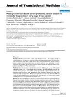
protein and peptide analysis by mass spectrometry
Bạn đang xem bản rút gọn của tài liệu. Xem và tải ngay bản đầy đủ của tài liệu tại đây (19.84 MB, 344 trang )
1
Mass Spectrometry in the Analysis of Peptides
and Proteins, Past and Present
Peter Roepstorff
When the editor, John Chapman, asked me to write the introductory chapter
to this volume and told me that it would be dedicated to the late Michael
“Mickey” Barber, I felt very honored and also humbled because I have always
considered Mickey to be one of the most outstanding pioneers in the field of
mass spectrometry (MS) of protems. Most younger scientists associate
Mickey’s name with the invention of ionization of nonvolatile compounds by
fast-atom bombardment (FAB) m 1981 (I). It is also true that this invention
had a major impact on the practical possibilities for mass spectrometric analy-
sis of peptides and proteins. However, only a few of the present generation of
scientists involved m MS of peptldes and proteins know that MS of peptides
was already an active field 30 years ago and also that Mickey’s career in many
ways reflects the development m the field through all these years.
In the 196Os, a number of groups had realized and actively investigated the
potential of MS for peptlde analysis. The only ionization method avallable was
electron impact (EI), which required volatile denvatlves. This necessitated
extensive derivatization of the peptides prior to mass spectrometric analysis.
The followmg groups were pioneers in investigating MS: the group headed by
M. Shemyakin at the Institute for Chemistry of Natural Products of the USSR
Academy of Sciences, which worked with acylated and esterlfied peptides
(2); K. Biemann’s group at Massachusetts Institute of Technology, which used
acylation followed by reduction of the peptides to ammo alcohols followed by
trimethylsilylatlon and gas chromatography (GC)/MS (3); and E Lederer’s
group at the Institute for Chemistry of Natural Substances in Gif sur Yvette,
France, which studied natural peptidolipids among other compounds. Mickey
Barber, who at that time worked at AEI in Manchester, got involved m the
From Methods In Molecular B/o/ogy, Vol 61 Protern and Pepbde Analysrs by Mass Spectrometry
E&ted by J R Chapman Humana Press Inc , Totowa, NJ
2
Roepstorff
work of E. Lederer. The French group had isolated a peptldohpld called
fortultine, which was analyzed by Mickey on the MS9 mass spectrometer
Fortultine appeared to be a very fortuitous compound. It was N-terminally
blocked with a mixture of fatty acids, was naturally permethylated, and con-
tamed an esterlfied C-termmus Mickey Barber obtained a perfect El spectrum
of this 1359-Da peptide and was able to interpret the spectrum (4). 1 believe that
this, at that time, was the largest natural compound ever analyzed by MS.
The achievement contains many of the elements now considered to be only
possible with the most contemporary MS techniques. Thus, heterogeneity both
m the sequence and the secondary modlficatlons was determined and the frag-
ment ions, always present in EI spectra, allowed sequencmg. The realization of
the effect of iV-methylatlon on the volatlhty of the peptldohprd resulted m
development of the permethylatlon procedure for peptlde analysis by MS (5)
For me, personally, the fortuitme paper has also been very fortmtous. Shortly
after Its publication, I became involved m peptlde synthesis by the Merrlfield
method, which, unfortunately, did not always yield the expected product. Modi-
fications, which researchers had no practical method to analyze, were frequent.
The fortultine paper inspired me to investigate the possible use of MS for analy-
sis of these modlficatlons. Smce then, MS has been my mam tool m protein
studies. A few years later, I first met Mickey during a visit to AEI m Manches-
ter. I was very fascinated by his lively engagement m the subject, and also
realized over a pmt of beer m a nearby pub that MS was not his only scientific
interest. He was deeply involved m surface science and had been also very
active in the development of equipment for photo-electron spectroscopy, as
well as in exploring the possibihties of electron spectroscopy for chemical
analysis (ESCA). Shortly after we first met, he moved from AEI to a lecture-
ship at the University of Manchester Institute of Science and Technology,
where he became a full professor m 1985. In the same year, he was elected
Fellow of the Royal Society.
In the 197Os, MS of peptldes progressed slowly and, although Its potential
was demonstrated by a number of applications to structure elucidation of modl-
fied peptides, the field was stagnating by the end of the decade. Two new ion-
ization methods, chemical lontzation and field desorptlon, appeared during that
period. They created new hopes for improvements m peptlde analysis by MS,
but unfortunately, they did not result m a real breakthrough
In that period, I had no real contact with Mickey Barber. It is my impression
that he, mtuitlvely or consciously, was realizing that the opening of new possl-
blhtles for mass spectrometric analysis had to come from surface science. Any-
way, among other subjects, he started to investigate surface analysis by
secondary-ion mass spectrometry (SIMS). This led to his discovery of a new
technique for desorptlon and ionization of mvolatile organic compounds. He
Mass Spectrometry
3
termed the technique FAB because, instead of the primary ions used m SIMS,
he used a beam of 3-l 0 keV argon atoms to effect desorption and iomzation.
The choice of atoms instead of ions was mainly determined by a desire to avoid
surface charging phenomena, which could disturb ion focusing m the sector
mstrument used. It was later realized that primary ions work just as well as
atoms, and the fast atom gun is now frequently replaced by a cesmm gun creat-
mg 20-30 keV primary cesmm ions.
The concept of SIMS of orgamc solids was not new. Benninghoven et al.
(6), at the University of Munster in Germany, had already, some years earlier,
demonstrated mass spectra of organic solids, mcludmg amino acids, by SIMS.
The spectra, however, were only transient because the surface was quickly
destroyed by the high flux of primary ions. As a matter of fact, the real discov-
ery by Mickey Barber was the use of a liquid matrix and the technique IS now
often termed hquid secondary-ion mass spectrometry (LSIMS) when a pri-
mary beam of cesium ions is used Instead of fast atoms. The trick of using a
matrix was that the matrix surface was contmuously replenished with sample
so that secondary ions could be produced continuously over a long period of
time. This feature also made the technique directly compatible with scanning
mass spectrometers. In fact, an important reason for the immediate success of
FAB was that it could readily be mstalled on existmg sector field and quadru-
pole mass spectrometers. In my own laboratory, for example, we installed FAB
in 1982 simply by replacing the standard solids inlet probe with a simple rod
and by placing an ion gun m the place of the GC mlet on a Varian MAT 3 1 IA
double-focusing sector Instrument. To my knowledge, Mickey was the first to
introduce the use of a matrix m MS and, as is described later in this chapter, the
use of a matrix is essential in all mass spectrometric techniques used for analy-
sis of peptides and protems.
Another technique that allowed the analysis of large, mvolatile organic mol-
ecules was plasma-desorption mass spectrometry (PDMS) developed as early
as 1974 by Torgerson et al. (7). The technique had been shown to be capable of
the analysis of large underivatized peptides (8), and, soon after, of proteins, by
the demonstration of the first mass spectrum of insulin in 1982 (9) and of a
number of snake toxms with molecular masses up to 13 kDa (ZO). Instrumen-
tation for PDMS became commercially available a few years later, and the
real breakthrough for this techmque came 2 years later with the simulta-
neous discoveries of the advantages of using nitrocellulose as support (2 2) or
reduced glutathione as matrix (12). Shortly after the publication of the PD-
spectrum of insulin, FAB mass spectra of insulin were also published (13,14),
and in the followmg years, mass spectra of proteins as large as 25 kDa were
published using both techniques, concomitantly with the gradual acceptance of
the potential of mass spectrometrtc analysts by a number of protein chemists.
4 Roepstorff
In that period, Mickey Barber visited my laboratory for a period during which
he “played” with our plasma-desorption mass spectrometers to get a personal
feeling of the potential of this technique compared to FABMS. Mickey’s
enthusiastic engagement made his stay a great mspiration for me as well as for
my students, and we had many long discusstons about the status and future
perspectives of the field It seemed to us that both techmques had fundamental
hmitations that would prevent then full acceptance among protem chemists.
The major limitations were that it was drffcult to extend the mass range beyond
25 kDa, and that this range could only be attamed for a few ideally behaved
protems. The sensitivity, which was m the low- to mid-picomole range, was
also not as good as desired, and finally, mixture analysis was SubJect to consid-
erable selectivity owmg to suppression effects.
In 1988, two new mass spectrometrtc techniques, which dramatically
extended the potential of MS for protein analysis, were published, and it was
soon appreciated that they were able to overcome most of the hmrtations men-
tioned. At the Amerrcan Society for Mass Spectrometry (ASMS) conference m
June m San Francisco, John Fenn from Yale University gave a lecture on the
apphcatton of a new ionization technique, termed electrospray ionization (ESI),
for protem analysts (15) Those of us who attended the lecture walked away
with the feeling that we had witnessed a real breakthrough for the mass spec-
trometrtc analysis of large btomolecules. A few months later at the Interna-
tional Mass Spectrometry Conference m Bordeaux, France, Franz Hillenkamp
gave a lecture descrtbmg another new tomzatton technique, matrix-assisted
laser desorption/iomzation (MALDI)
(16).
In this lecture, he showed molecu-
lar ions of proteins up to 117 kDa using time-of-flight analysis. MALDI
seemed at least as promising for protein analysis as ESI.
A few years later, commercial mstruments were available for both tech-
niques, and the questron was really which of the two techniques would be the
future method of choice m the protein laboratory. In fact, at present, I consider
the two techniques to be highly complementary. They have both dramatically
improved the perspectives for the application of MS in protein chemistry to
such an extent that a protein chemistry laboratory without access to these two
techniques or at least one of them cannot be considered up to date. A common
feature of both techniques is that, if the idea of a matrix IS considered in its
widest sense, both can be considered to be matrix-dependent Just as FAB and
PD. MALDI IS, as indicated by its name, a matrix-dependent method. How-
ever, ESI, in spite of an entirely different ionization mechanism, can be consid-
ered to be matrix-dependent, since a prerequisite is that the analyte IS dissolved
m an appropriate solvent prior to ion formation m the electrospray process,
Mickey, unfortunately, died in May 1991, and therefore did not get the
chance to see how his dream about the role of MS m protein studies and hts
Mass Spectrometry 5
concept of usmg a matrrx have made then triumphal progress durmg the past
5 years. We m the scienttfic commumty have been deprived of the posstbihty
to obtain his interpretation of which elements are common to the four tech-
niques that have created the progress in MS applied to protein chemistry In the
absence of hts mterpretation, I will try to use the way of thinking and argumg I
have experienced m my dtscusstons with Mickey to outline what I consider to
be the main function of the matrix. This 1s independent of whether tt 1s the
nitrocellulose support in PD, the liquid matrix in FAB, the solid matrix m
MALDI, or the solvent m ESI.
A common feature 1s that the matrix/support is present in a large molar
excess relative to the analyte. This indicates that a prime purpose of the matrix
is to isolate the protein molecules and prevent aggregation Next, the matrix
must create a platform that can be removed, leaving the single analyte mol-
ecules free in the gas phase. This 1s effected by different means m the four
techniques. In PDMS, the mtrocellulose support most likely decomposes on
high-energy impact, so that the analyte molecules are left free and pushed off
the surface by the resultmg pressure wave. In FAB, the analyte molecules are
sputtered from the liqutd matrix surface, maybe still partly solvated in
microdroplets of ltquid matrix, followed by desolvatton by multiple colhsions
just above the matrix surface. In MALDI, the solid matrix absorbs most of the
laser energy, and decomposes or evaporates leaving the analyte molecules free
m the expanding matrix plume. Finally, in ESI, the mtcrodroplets created in
the electrospray process by combined evaporation and coulombic explosions
are subdivided until each droplet contains only one or a few analyte molecules,
which, on final desolvatton, leaves the analyte molecules free. The last step is
that the analyte molecules must be ionized. Several different ionization mecha-
nisms are wtthout doubt operattve m the different techniques and also within a
single technique. In PD, FAB, and MALDI, chemical iomzatton is most likely
to be the dominant tomzatton mechanism, although preformed ions, as well as
other mechanisms, may also play a role. The iomzatton mechamsm in ES1 is
still controversial, and tt ts outside the scope of this introductory chapter to
enter thrs debate.
In summary, the matrix serves to isolate single analyte molecules, to create
a removable platform from which the analyte molecules can be brought mto
the gas phase, and to create a medium that can tomze the analyte molecules. To
be able to create ions of the proteins ts, however, not suffictent to make the
techniques usable in the protein laboratory. They must be compatible with the
procedures generally used m protein chemistry m terms of senstttvtty and
acceptance of solvents, detergents, and buffers, They must be able to handle
impure samples and complex mixtures. Last, but not least, the information
gained must be of sufficient value to justify the effort and cost needed to obtain
6
it. The numerous apphcations of MS to protein studies published during the
last decade and the rapid acceptance of MS m the protein community clearly
show that these conditions are now fulfilled. The followmg chapters m thts
volume describe these mass spectrometric techniques in detail and demonstrate
a wide variety of applications: The use of MS for protein identificatton m com-
bination with high-resolutton separation techntques, such as 2D-PAGE, its
compatibthty with buffers and detergents, and its use m combinatron wtth
HPLC are illustrated. Several methods for the sequencing of pepttdes, determi-
nation of disulfide bonds, and different methods for the localization and struc-
ture determmatlon of secondary modificattons, including glycosylation, are
described. Even examples of tasks considered very dtfficult, such as the analy-
sis of very hydrophobic protems (e.g , membrane proteins), the highly specific
quantitation of btologrcally active pepttdes, and studies of noncovalent mter-
actions between protems or between protems and low-mol-wt hgands, are now
wtthm reach. In my mind, there IS no doubt that MS will be an essential tech-
nique m
all protein
studies m the future.
References
1, Barber, M , Bordoh, R. S., Sedgwick, R. D., and Tyler, A. N (1981) Fast
atom
bombardment of solids (FAB) a new ion source for mass spectrometry J Chem
Sot Chem Commun 1981,325-327
2 Shemyakm, M. M , Ovchinnikov, Yu. A., Kiryushkin, A A., Vinogradova, E I ,
Miroshmkov, A I., Alakhov, Yu. B., et al. (1966) Mass spectrometric determina-
tion of the ammo acid sequence of peptides Nature 211,361-366
3 Biemann, K and Vetter, W (1960) Separation of peptide derivatives by gas chro-
matography combmed with mass spectrometrtc determmation of the ammo acid
sequence. Blochem Blophys Res Commun 3,578-584
4 Barber, M., Jolles, P., Vilkas, E , and Lederer, E. (1965) Determmation of ammo
acid sequence in oligopeptides by mass spectrometry. I The structure of
fortuitme, an acyl-nonapeptide methyl ester Biochem Bzophys Res Commun
l&469-473
5 Das, B C , Gero, S D , and Lederer, E. (1967) N-methylation of N-acyl
ohgopeptides Blochem Bzophys Res Commun 29,2 1 l-2 15
6. Benninghoven, A., Jaspers, D , and Srchtermann, W. (1976) Secondary-ion emts-
sion of ammo acids. Appl. Phys 11,35-39.
7 Torgerson, D F., Skowronski, R P , and Macfarlane, R D (1974) New approach
to the mass spectrometry of non-volatile compounds. Btochem Bluphys. Res
Commun 60,616-621
8 Macfarlane, R. D and Torgerson, D F. (1976) Californium-252 plasma desorp-
tion mass spectrometry Sczence 191,92&925.
9. Hakansson, P , Kamensky, I , Sundqvist, B., Fohlman, J., Peterson, P., McNeal,
C. J., and Macfarlane, R. D (1982) 127-I plasma desorption mass spectrometry of
insulm J Am Chem Sot 104,2948,2949
Mass Spectrometry
7
10
11
12.
13
14
15
16
Kamensky, I., Hakansson, P , KJellberg, J., Sundqvist, B , Fohlman, J., and
Petterson, P. (1983) The observation of quasi molecular ions from a tiger snake
venom component (MW 13309) usmg 252-Cf plasma desorption mass spectrom-
etry FEBS Lett 155, 113-l 16
Jonsson, G. P , Hedm, A B , Hbkansson, P L , Sundqvist, B U R , Save, G S ,
Nielsen, P F , et al ( 1986) Plasma desorption mass spectrometry of peptides and
proteins absorbed on mtrocellulose Anal Chem 58, 1084-1087
Alai, M , Demirev, P , Fenselau, C , and Cotter, R J (1986) Glutathione as matrix
for plasma desorption mass spectrometry of large peptides Anal Chem 58,
1303-1307
Dell, A and Morris H R (1982) Fast atom bombardment-high field magnetic
mass spectrometry of 6000 Dalton polypeptides Blochem Blophys Res Commun
106, 14561461
Barber, M , Bordoh, R S , Elhot, G J , Sedgwick, R D., Tyler, A. N., and Green,
B N. (1982) Fast atom bombardment mass spectrometry of bovine msulm and
other large peptides J Chem Sot Chem Commun 1982,93&938
Meng, C. K , Mann, M , and Fenn, J B (1988) Electrospray Ionization of Some
Polypeptides and Small Proteins Proceedings of the 36th ASMS Conference on
Mass Spectrometry and Allied TOPICS, San Francisco, CA, June 5-10, pp 77 1,772
Hillenkamp, F (1989) Laser desorption mass spectrometry’ mechanisms, tech-
niques and apphcattons, m Advances in Mass Spectrometry, vol
11 (Longevialle,
P , ed ), Heyden and Sons, London, pp 354-362
Ionization Methods and Instrumentation
John R. Chapman
“ There’s Jasmine! Alcohol there’ Bergamot there’ Storax there’ Grenoutlle went
on crowmg, and at each name he pointed to a drfferent spot m the room, although rt was
so dark that at best you could only surmrse the shadows of the cupboards filled with
bottles ” (Patrick Sushnd, Perfume)
1. Introduction
Mass spectrometry (MS) (I) IS one of the most important physical methods
in analytical chemistry today A particular advantage of MS, compared wrth
other molecular spectroscopies, IS its hrgh sensrtrvity, so that It provides one of
the few methods that 1s entirely suitable for the identrficatron or quantrtatrve
measurement of trace amounts of chemrcals. A mass spectrometer, m Its srm-
plest form, IS designed to perform the following three basic functions:
1 Produce gas-phase ions from sample molecules. This IS accomplrshed tn the ion
source and, at one time, would normally have required these neutral molecules to
be already m the vapor state. New tonizatron techniques have, however, extended
thus process to neutral molecules whtch are essentially in a solid (condensed)
state or in solution
2 Separate gas-phase ions according to their mass-to-charge (m/z) ratio. Thus takes
place m the analyzer.
3. Detect and record the separated tons
Conventionally, the process of ion formation, just like ion analysis and
detection, takes place u-r a vacuum. Some more recent methods, however, use
instruments in which ions are produced in a source that operates at atmospheric
pressure, although analysis and detection still require a vacuum environment.
From Methods m Molecular Biology, Vol 61 Rote/n and Pepbde Analysrs by Mass Spectrometry
Edited by J R Chapman Humana Press Inc , Totowa, NJ
9
10 Chapman
Table 1
ionization Methods
Ionization
method
Sample Thermal input
preparation associated
for ionization with iomzatton
Method
category
EI
CI
FAB
MALDI
TS
ES
(or ton spray)
APCI
As vapor
As vapor
Dissolved m
matrix such
as glycerol
Mixed with
matrix, such as
smapmic acid
Dissolved in
solvent
Dissolved m
solvent
Dissolved m
solvent
Relatively high
Relatively high
Vrrtually none
Virtually none
Moderate
Virtually none
Moderate
Thermal
Thermal
Energetic
particle
bombardment
Energetic
particle
bombardment
Field
desorption
(in some cases)
Field
desorption
Thermal
A large number of different mstrumental configurations can be used to per-
form these three functions. For example, there are different sample inlet sys-
tems, different methods of ionization, and different mass analyzers. This
chapter first looks at the various methods of ion formation that are available, m
particular those that are applicable to macromolecules. The remainder of this
chapter then deals with mass analyzers.
2. Ionization Methods
The ionization methods (I) that are generally avatlable are summarized in
Table 1.
2.1. Electron lonizafion
Electron ionization or electron impact (EI) was the first ionization method
to be used routinely and is still the most widely employed method in MS over-
all. Although of only marginal relevance m peptide and protein analysis, EI
can convemently be used to describe the main features of a mass spectrum. The
EI source IS a small enclosure traversed by an electron beam that originates
from a heated filament and is then accelerated through a potential of about 70 V
into the source. Gas-phase molecules entering the source interact with these
electrons, As a result, some of the molecules lose an electron to form a posi-
lomzat/on and lnstrumentat~on 11
Molecular ion
/
m/z (mass to charge ratlo)
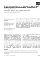
Fig. 1. EI spectrum of methylnaphthalene.
tively charged ion whose mass corresponds to that of the original neutral mol-
ecule. This is the molecular ion (Eq. [ 11). Many molecular ions then have suf-
ficient excess energy to decompose further to form fragment ions that are
characteristic of the structure of the neutral molecule (Eq. [2]).
A-B 3 [A-B]+‘+ e-
(1)
[A-B]+‘+A++B’
(2)
Thus, the molecular ion gives an immediate measurement of the molecular
weight of the sample, whereas the mass and abundance values of the fragment
ions may be used to elicit specific structural information. Taken together the
molecular and fragment tons constitute the mass spectrum of the original com-
pound (Fig. 1). Overall, an EI spectrum of an organic compound may be used as
a fingerprmt to be compared with existmg collectrons of mass spectra. The prm-
cipal collections of reference spectra, which are available m data system-com-
patible form, represent some 200,000 separate compounds. Computer-based
searching of library data has other apphcattons m MS, some of which (e.g.,
Chapter 6) are of more immediate relevance to peptide and protem analysis.
One other aspect of the spectrum in Fig. 1 that should be noted is the exist-
ence of isotope peaks, which correspond to the molecular ion and to each frag-
ment ton. For example, although the molecular ton, at
m/z
142, has the
compositton Ct ,Hto, its isotope ion, at
m/z
143, has the composrtton C,o’3CH,o.
12 Chapman
A more detailed consideration of the effects of isotope peaks 1s presented m the
Appendix section of the book.
El is suttable for the analysts of a large number of synthetic and naturally
occurring compounds, but is limited by the need for sample vaporization prior
to ionization. Thus, the conventional thermal vaporization routines that are
used m conJunctton with EI mean that this techmque is quite unsuitable for
the labile, mvolatile compounds that are encountered m btologtcal work. On
the other hand, the couplmg of EIMS with capillary gas chromatography
(GCYEIMS) is certamly the most widely used analytical technique m organic
MS today.
2.2. Chemical Ionization
In chemical iomzatton (Cl) MS (2), ions that are characteristic of the analyte
are produced by ion-molecule reactions rather than by EI. Again, Just as with
El, the direct relevance of CI to pepttde and protem analysis is small, but the
basic Cl process 1s very likely an integral part of more relevant ionizatton meth-
ods (v&e znfra)
CI requires a high pressure (approx 1 torr) of a so-called reagent gas held m
an ton source that 1s basically a more gas-tight version of the El source. El of
the reagent gas, which is present m at least 1 O,OOO-fold excess compared wtth
the sample, eventually produces reagent ions (see Eqs. [3] and [4] for typical
reactions of methane reagent gas), which are etther nonreacttve or react only
very slightly with the reagent gas itself, but which react readily, by an ion-
molecule reactton (Eq [5]), to tomze the sample.
CH4 -+ CH4+', CH3+,CH2+'
(3)
CH‘,+'+CH,+ CH5++CH;
(4)
M+CH5++MH++CH,,
(5)
Thus, although many compounds fail to give a molecular ton in EI, the ener-
getically mild ion-molecule reacttons m Cl afford an intense quasimolecular
ion, mdicative of molecular weight, with the same sample. For example,
reagent tons from isobutane or methane tomze sample molecules by a proton
transfer process (Eq. [5]), which leads to a posttively charged quasimolecular
ion at a mass that is 1 u higher than the true molecular weight. In addttton,
unlike EI, which produces only positive tons, CI can be used to produce useful
ion currents of positive or negative tons representative of different samples.
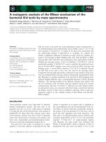
Exammation of the Cl spectrum of htstamme (Fig. 2) tllustrates both the
advantage (mol-wt information) and the possible disadvantage (little or no frag-
ment ion information) of Cl. Just as with El, however, a maJor disadvantage of
Cl 1s the need for sample vaporizatton prior to tonization, whtch again rules
Ionization and Instrumentation
32
A
CH2CH2NH2
13
12 WHI+
B
Fig. 2. (A)
Electron impact and
(B)
CI spectra of histamine (M, 111)
out any application to higher mol-wt, labtle materials. On the other hand, CI
processes, for example, the formation of (M + H)+ ions, are implicated in a
number of iomzatton techniques, such as fast-atom bombardment (FAB) (Sec-
tion 2.3.) and matrix-assisted laser desorption/ionization (MALDI) (Section
2.4.), which are used for the analysis of macromolecules, as well as m tech-
niques such as thermospray (TS) (Section 2.7.) and atmospheric pressure
chemical ionization (APCI) (Section 2.6.), which can be used for the liquid
chromatography (LC)/MS analysis of relatively labile molecules.
2.3. Ionization by fast-Atom Bombardment (FAB)
The mtroductron of FAB (3) as an ionization method marked the first entry
of an energetic-particle bombardment method (Table 1) mto routme analysis,
as well as the effective entry of MS mto the field of bropolymer analysis. In such
methods, the impact of an energettc particle initiates both the sample volatilization
and ionization processes so that separate thermal volatilization is not required.
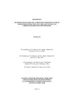
In the FAB source, a beam of fast moving neutral xenon atoms, (a) m Fig. 3,
directed to strike the sample (b) which is deposited on a metal probe tip (c),
14
Chapman
Atom gun
(a) Neutral alom beam ~
(c) Probe tip
(d) ExtractIon and focusing
Fig.
3. FAB ion source.
produces an intense thermal spike whose energy is dtssipated through the outer
layers of the sample lattice. Molecules are detached from these surface layers
to form a dense gas containmg positive and negative ions, as well as neutrals,
Just above the sample surface. Neutrals may subsequently be ionized by ion-
molecule reactions within this plasma. Depending on the voltages used, posi-
tive or negative ions may be extracted into the mass analyzer (e). Subsequently,
the neutral primary beam was replaced by a beam of more energetic primary
ions, such as Cs+, and this technique was named liquid secondary-ion mass
spectrometry (LSIMS) (4).
With a dry-deposited sample, there is a rapid decay m the yield of sample
ions owmg to surface damage by the incident beam. In FAB, however, the
sample IS routmely dissolved in a relatively mvolatile liquid matrix, such as
glycerol. The use of a liquid matrix, which is an absolutely crucial element m
the success of this method, provides continuous surface renewal, so that
sample ion beams with a useful intensity may be prolonged for periods of
several mmutes. In addition, the matrix behaves, in the vapor phase, m the
same way as a reagent gas m CI, for example by protonating the analyte (to
form an [M + H]+ ion) m the positive-ion mode. Most other methods for the
analysis of involatile and/or labile materials (e.g., MALDI [Section 2.4.1 and
electrospray (ES) ionization [Section 2.5.1) also use a matrix m some form.
Ionization and Instrumentation
15
Secondary ion beam
I I ’ - Toanalyzer
I I
Liquid flow
from LC __to
t I
wlth added
FAB matrix
/(
I
I
Silica capillary
I \
< o\,
I I
Probe body
Metal tip
Extractlon and
focusing
Optional
Heat and
absorbent Continuous
electrical
wick
liquid film
contact vla
source block
Fig.
4. Continuous-flow FAB ion source and liquid inlet.
The introduction of FAB saw the immediate extension of MS to the analysis of a
wide range of thermolabile and ionic materials, as well as to biopolymers, such as
peptides, oligosaccharides, and oligonucleotides. FAB is a relatively mild ionization
process, so that fragment ions are generally of low abundance, or, particularly with
analytes of higher molecular weight, absent altogether. Useful fragmentation can,
however, be deliberately introduced by the use of MS/MS techniques (Section 3.1.).
FAB is also the basis of an effective coupling technique for LC/MS, viz.
continuous-flow FAB (CF-FAB) (4). In this technique (Fig. 4), a liquid flow,
which is typically 5-10 pL/min split from the LC effluent, is directed toward a
gently heated FAB source via a narrow fused-silica capillary. The flow, to
which -0.5% glycerol matrix has been added, enters the source through a small
metallic frit interposed between the the capillary exit and the mass spectrom-
eter vacuum. Not only is the metal surface of the frit easily wetted, but the
thermal conductivity of the metal surface and the narrow orifices in the frit also
encourage a stable liquid-evaporation process. As a result, the liquid flow forms
a continuous film on the probe tip in which previously eluted sample is con-
tinually removed from the area where FAB takes place. An additional tech-
nique, sometimes used to promote a stable liquid film, is to place a layer of
absorbent material against the edge of the probe to remove liquid from the tip.
2.4. Matrix-Assisted Laser Desorp tion/lonization (MA L DI)
Another obvious source of energetic particles for sample bombardment is
the laser. Just as with FAB, the successful use of a laser was found to depend
on the provision of a suitable matrix material with which the sample is admixed.
16
Chapman
/
laser
1.
lens
I llr- I
,
. . .i.;ii” “i
t
7 - - -’ -’
-1 - . .
sample
slide
lens
. . *-
_ -
_ electron
n
multlpher
reflectron
Fig. 5. MALDI source installed on a time-of-flight analyzer (Section 3 ). Both linear
and reflectron analysis modes are shown
In this way, the technique of MALDI (Fig. 5) was conceived. In MALDI (.5J,
the matrix material (generally a solid and again present in large excess) absorbs
at the
laser wavelength
and thereby transforms the laser energy mto excitation
energy for the solid system, a process that leads to the sputtering of surface
molecular layers of matrix and analyte. A typical MALDI matrix compound
(Appendix) displays a number of desirable properties:
1, An ability to absorb energy at the laser wavelength, whereas the analyte gener-
ally does not do so
2 An ability to isolate analyte molecules wtthm some form of solid solution
3 Suffictent volatiltty to be rapidly vaporized by the laser m the form of a Jet m
which intact analyte molecules (and tons) can be entrained.
4 The appropriate chemistry
so that matrix molecules excited by the laser can ion-
ize analyte molecules, usually by proton transfer.
Using this technique, ionized proteins with molecular masses in excess of
200 kDa are readily observed-considerably greater than anything previously
achieved. MALDI is, m fact, applicable to a wide range of biopolymer types,
e.g., proteins, glycoprotems, ohgonucleotides, and ohgosaccharides. Again,
with an appropriate choice of matrix, MALDI is more tolerant than other tech-
niques toward the presence of inorganic or organic contammants (Appendix VI).
Thus, compared with FAB, MALDI has enormously extended the mol-wt and
polarity range of samples for which an MS analysis is possible while providmg
an analytical technique that is easy to use and can be more tolerant of the diffi-
culties encountered m purifying biochemrcal samples.
The prmclpal ion seen m most MALDI spectra IS an (M + H)’ “molecular”
ion. As the analyte molecular weight increases, however, doubly charged ions,
(M + 2H)2+, also will be detected, and triply charged analogs, and so forth, may
be detected at still higher molecular weights. In addition, signals that corre-
spond to molecular clusters, e.g , dlmers (2M + H)+ and trlmers (3M + H)‘, may
also be found m MALDI spectra. Negative-ion MALDI spectra are Just as eas-
ily recorded and also show an equivalent range of molecular-ion types. Any of
these “molecular” ions can provide a direct measurement of the molecular
weight of the analyte, but useful fragmentation 1s usually absent. Recent devel-
opments (Chapter 4), however, have provided methods by which structurally
meaningful fragment ions may be recorded m MALDI.
Unlike any of the iomzatlon techniques mentioned so far, MALDI differs
insofar as It 1s a dlscontmuous iomzatlon technique. Analyte ions are only pro-
duced, for a very short period, each time the laser is fired. For this reason,
conventional scanning analyzers, which operate on an mapproprlate time scale,
are replaced by a time-of-flight mass analyzer (Section 3.) for MALDI. Alter-
natively, the use of an integrating detector, with a magnetic sector analyzer for
example, IS also suitable for MALDI (Chapter 18).
2.5. Electrospray (ES) and Ion-Spray Ionization
In the ES ionization process (6), a flow of sample solution 1s pumped through
a narrow-bore metal capillary held at a potential of a few kilovolts relative to a
counterelectrode (“filter” m Fig. 6B). Charging of the liquid occurs, and as a
result, it sprays from the capillary orifice as a mist of very fine, charged drop-
lets. This spraying process takes place m atmosphere and the whole lonrzatlon
process IS, m fact, a form of atmospheric pressure ionization (API).
The charged droplets, with a flow of a warm drying gas to assist solvent
evaporation, decrease m size until they become unstable and explode (Cou-
lomb explosion) to form a number of smaller droplets. Finally, at a still smaller
size, the field due to the excess charge 1s large enough to cause the desorp-
tlon of ionized sample molecules from the droplet. These ions, which are field
desorbed (Table 1) from the droplets at atmospheric pressure, are then sampled
through a system of small orifices with differential pumping, mto the vacuum
system for mass analysis
ES ionization is a very mild process, with little thermal input overall, by
which analyte ions may again be derived from molecules with molecular
weights m excess of 100 kDa. Fragmentation is virtually absent, and only
mol-wt information is available from the spectra. Useful fragmentation can,
however, be deliberately induced when using ES, ion-spray (v&e infra), or
APCI (Section 2.6.), either by MS/MS techniques (Section 3.1.) or by an
increase in the voltage between the cone plates in Fig. 6B. Thus, with a lower
18
Chapman
Dtying gas
Adjustable skimmer
Transfer optics
cone
I
Drying gas
Adiustable skimmer
Transier optics
cone
Fig.
6. (A) APCI source and (B) ES/ion-spray ion source. (Courtesy VG Instru-
ments, Manchester, UK.)
voltage difference, ions will pass undisturbed through the intermediate pres-
sure region between these plates. On the other hand, an increase in the voltage
difference causes sample ions to undergo more energetic collisions with gas
molecules in this region, and, as a consequence, the ions can dissociate into
structurally significant fragment ions. Unlike the use of MS/MS techniques,
however, this in-source collision-induced dissociation (CID) is not selective
and has some effect, at a given voltage difference, on a significant proportion
of all the different ion types passing through the region.
A particular feature of ES ionization spectra is that the molecular ions
recorded are multiply charged, (M + nH)“+, in the positive-ion mode, or (M -
nH)“- in the negative-ion mode, and also cover a range of charge states. On
average, one charge is added per 1000 Da in mass. Since mass spectrometers
separate ions according to their mass-to-charge (m/z) ratio, rather than their
mass, this means that, for example, an ion of mass 10,000 which carries 10
charges will actually be recorded at m/z 1000, thereby reducing the m/z range
required from any analyzer. This is an especially convenient feature, since ES
ionization is, by this means, able to generate, from relatively massive mol-
loniza tion and Instrumentation 19
ecules, ions that can readily be analyzed using a simpler “low-mass” analyzer,
such as a quadrupole mass filter (Section 3.).
In the ion-spray techmque (Fig. 6B), a flow of nebulizmg gas m an annular
sheath, which surrounds the spraying needle, is used to mput extra energy to
the process of droplet formation. Using this technique, the practical upper limit
for the liquid flow that can be sprayed to provide a stable ion current is
increased from perhaps 10 uL/mm in earlier ES sources to approx 1000 pL/min
m newer ion-spray sources. Ion-spray also offers increased tolerance toward
the presence of higher water levels in the solvent flow as well as being less
affected by the presence of electrolytes and, as a result, provtdes a more robust
system that is overall more suitable than ES for LC/MS.
With either ion-spray or ES, the coupling of low-flow chromatographic sys-
tems requires the use of a make-up flow, in the form of a liquid sheath around
the spraying needle, to increase the liquid flow rate to a suitable value and/or to
provide an overall solvent composition that is suitable for electrospraymg. In
general, LC/MS operation benefits from the very much simpler mterfacmg
afforded by the use of an atmospheric pressure ion source In particular, source
access is excellent, and there are no vacuum effects that might affect the per-
formance of lower flow columns.
ES and ion-spray iomzation offer methods for the mol-wt determination of
protems and other biopolymers with very acceptable accuracy, and also offer
convenient access, particularly by m-source dissociation, to some fragment-
ion information. Again, as techniques m which ionization takes place m the
liquid phase, they are highly compatible, especially m the ion-spray configura-
tion, with LC/MS operation. On the other hand, ES is somewhat more suscep-
tible to the presence of impurities and therefore perhaps less useful than
MALDI as a “first-pass” analytical method.
2.6. Atmospheric Pressure Chemical loniza tion (APCI)
In APCI (7), the hquid flow, which carries the sample and which enters the
atmospheric pressure source through a narrow tube, is nebulized by a coaxial
stream of gas and by thermal energy from an adjacent heater (Fig. 6A). This
process produces a vapor that contams both sample and solvent, and which is
subsequently ionized by a corona discharge established, still m atmosphere,
from an electrode located just after the nebuhzmg inlet.
Ionization of the sample takes place by means of a chemical iomzation pro-
cess, at atmospheric pressure, in which the solvent vapor is imttally ionized by
the discharge and then, very efficiently, ionizes sample molecules. This last
step is an ion-molecule reaction with, for example, proton transfer from spe-
cies such as H(H,O)’ m the positive-ion mode or reaction with solvated O*- in
the negative-ion mode. A stream of drying gas removes most clustermg sol-
Chapman
vent molecules from the sample ions and prevents solvent neutrals from enter-
mg the mass analyzer. As with ES, the products of these atmospheric pressure
processes are sampled, via a system of orifices, mto the vacuum system of the
mass spectrometer for mass analysis.
APCI provides a good basis for practical LCYMS mterfacmg. The APCI source
can handle l-2 mL/min of most solvents, and the atmospheric pressure config-
uration simplifies mterfacmg and provides a source that is very often more sensi-
tive than alternative techmques, such as TS (Sectron 2.7.). The large overall size of
the source, together with careful routing of gas flows, means that wall collisions
are minimized during the tomzatron process and, as a result, relattvely labile
molecules may be analyzed routmely by LC/APCI-MS. Despite these advan-
tages, however, the use of thermal volatrlization (cf Table 1) prior to tonizatton
means that APCI is not directly applicable to the analysis of proteins or peptides.
2.7. Thermospray (TS) loniza tion
In the TS tonization process (a), a volatile electrolyte, usually ammonium
acetate, is added to an aqueous or partly aqueous solution of the sample, which
flows through a heated capillary, introduced mto the TS source. The capillary
heating vaporizes most of the liquid flow so that the remainder, with the sample
and ammomum acetate still m solution, 1s sprayed from the capillary exit, by
the vapor, mto the ion source. Although the solution is overall electrically neu-
tral, statistical fluctuations ensure that each of these tmy droplets bears a slight
excess positive or negative charge from the added ammonium acetate.
As in ES ionization (Section 2.5.), the charged droplets decrease m size
owing to evaporation until they become unstable and explode to form much
smaller droplets, Under appropriate conditions, the desorptton of intact ion-
ized sample molecules from the smallest highly charged droplets 1s possible.
Alternatively, since the ion source, unlike ES, operates at an elevated tempera-
ture, more volatile neutral analyte molecules may be transferred directly to the
gas phase during the droplet evaporation process and then ionized by an ion-
molecule process. If the TS source is used with a mainly organic solvent, msuf-
ficient ionization occurs unless an auxiliary source of tons, such as a heated
filament or discharge electrode, is used. TS tonization is a relatively mild ton-
ization process, so that, in many cases, only ions indicative of the molecular
weight are seen and structurally informative fragment ions are absent. Again,
however, MS/MS may be used as an ancillary technique.
TS is also a practical LC/MS interfacing technique that, owing to the rotary
pump attached to the ion source, will readily accept flow rates of l-2 mL/mm.
This pump is able to remove most of the solvent vapor so that only a small
fraction has to be pumped via the source housing. The same source, with the
assistance of an additional discharge electrode or filament, will also accept a
Ionization and lnstrumentatlon
21
Table 2
Upper m/z Value and Resolving Power (RP)
for Various Mass Analyzers
Mass analyzer
m/z”
RPa
Quadrupole
Double-focusmg sector
Trme-of-flrght
Ion trap
FTMS
4000
10,000
1 ,ooo,ooo
2500
Hrgh, but
see RP
Unrt mass
50,000
500
Generally low
High, e g , >>50,000,
but depends on
m/z
OThese figures relate to routme use and do not represent an absolute hmlt to
techmcal capablhtles
Ion source
detector
Rod assembly
Fig. 7.
Schematrc of a quadrupole mass analyzer.
wide range of solvent polarities. TS has been used for the analysis of many
different solute types, including small peptides, but shows poor sensmvny with
higher mol-wt analytes, and has not been used m a practical manner for the
analysis of peptides or proteins.
3. Mass Analyzers
The function of the mass analyzer (Table 2) is to separate Ions according to
then mass-to-charge (m/z) ratio. Figure 7 shows one of the most commonly
used analyzers-the quadrupole mass filter (9). In this device, a voltage made
up of a DC component U and an RF component Vcos c& IS applied between
adjacent rods of the quadrupole assembly, whereas opposite rods are connected
electrrcally. With a correct choice of voltages, only ions of a given m/z value
Chapman
l
Fig. 8. SchematIc of a double-focusing magnetic sector analyzer
can traverse the analyzer to the detector, whereas ions havmg other
m/z
values
collide with the rods and are lost. By scanmng the DC
and RF voltages, while
keeping their ratio constant, ions with different
m/z
ratios will pass succes-
sively through the analyzer. In this way, the whole
m/z
range may be scanned
and a complete mass spectrum recorded.
In a magnetic sector analyzer (Fig. S), accelerated Ions are constrained to
follow circular paths by the magnetic field. For any one magnetic field strength,
only Ions with a given
m/z
ratio ~111 follow a path of the correct
radius to arrive
at the detector. Other ions will be deflected either too much or too little. Thus,
by scannmg the magnetic field, a complete mass spectrum may be recorded,
Just as with a quadrupole analyzer. When the magnetic analyzer is operated in
conjunction with an electrostatic analyzer (Fig. 8), the instrument then pro-
vides energy as well as direction focusing and 1s capable of attaining much
higher mass resolution. This double-focusing magnetic sector instrument (10)
1s also much more suitable than the quadrupole analyzer for the analysis of
ions of higher
m/z
ratio. Detection of ions is accomplished, m all the mstru-
ments discussed so far, by a device, such as an electron multiplier, placed at the
end of the analyzer. The output from the electron multiplier 1s then dlrected
toward some kind of recording faciltty, usually a data system.
lotwa tion and Ins trumen ta t/on 23
For routme analyses, the foregoing analyzers can be operated m one of two
modes. The first of these 1s the scanning mode where the mass analyzer 1s scanned
over a complete mass range, perhaps from
m/z
1000 to
m/z
40 and usually repeti-
tively, in order to record successive full spectra throughout an analysts. This
mode of operation provides a survey analysis where the spectra provtde mforma-
tion on every component that enters the ion source during the analysts The other
mode 1s called selected-ion momtormg (SIM). In this case, the mstrument IS set
to successively monitor only specific
m/z
values, chosen to be representative of
compounds sought. This type of analysis detects only targeted compounds, but
does so with a much higher sensmvtty because of the longer monitormg time
devoted to the selected
m/z
values compared with the scanning mode.
Magnetic sector analyzers have been used in high-mol-wt analysts for some
time because of thetr high specificattons for
m/z
range and mass resolution
(Table 2) and because of their versatility, e.g., as part of more complex MS/MS
mstruments (Section 3.1.) or used wrth an integrating detector (Chapter 18)
Quadrupole analyzers now provide equally useful facilities in the high-mol-wt
area through the analysis of multiply charged ions from ES ionization (Section
2.5.). In addition, although certamly of lower spectfication, quadrupoles
demand a less sophtsticated approach to operatton and can be more tolerant of
operation at high pressure. Again, the quadrupole analyzer 1s also an integral
part of many MS/MS mstruments (Section 3.1.).
A third analyzer system, which is increasmgly commonly used, notably with
MALDI, 1s the time-of-flight analyzer (11) (Fig. 5). In this simple device, tons
are accelerated down a long, field-free tube to a detector. The
m/z
ratto of each
ion is calculated from a measurement of the time from thetr start, e.g., the
ion-formation laser pulse m MALDI, to the time at which they reach the detec-
tor. Unlike the quadrupole and magnetic sector analyzers, ions with an
m/z
ratio other than that which 1s being currently recorded are not rejected; all tons
that leave the ion source can, in prmciple, reach the detector. With this type of
mstrument, therefore, there 1s no real distinction between scanning and SIM
modes. A time-of-flight analyzer of improved mass resolution, the so-called
reflectron instrument, uses an electrostatic mirror to compensate for energy
differences among the ions.
As mentioned m Section 2.4., a ttme-of-flight analyzer is ideally suited to
the analysis of ions that are created on a discontinuous basis, e.g., as the result
of a laser pulse in MALDI. Time-of-flight analyzers have a very high sensittv-
tty and a vitually unlimited
m/z
range (Table 2), but generally have not offered
a particularly good mass resolutton, although recent developments m this area
(12)
are very encouragmg
Another analyzer that does not distmguish between the scanning and SIM
modes 1s the ion-trap analyzer (13) (Fig. 9). Ions are either made within the
24
Chapman
Filament
u A
B
T
Electron multiplier
Fig. 9. Schematic of a quadrupole ion-trap analyzer.
trap,
e.g., by EI, or injected into the trap from an external ion source, over a
short period of time. These ions are then maintained in orbits within the box-
like trap by means of electrostatic fields. After the ion formation period, ions
within the trap are ejected, in order of
m/z
ratio, so that a conventional spec-
trum is recorded. Again, all ions that are formed within the ion source are even-
tually recorded. The ion trap is particularly of interest because of its suitability
for a range of MS/MS experiments (Section 3.1.). The Fourier transform-ion
cyclotron resonance (FTMS) instrument (14) (Fig. 10) is also based on a trap-
ping analyzer, in this case, located within the solenoid of a superconducting
magnet. A particular feature of FTMS instruments is their very high mass reso-
lution (e.g., Chapter 9). A further advantage, as with the ion trap, is its suitabil-
ity for a range of MS/MS experiments (Section 3.1.).
3.1. MS/MS Instruments
Tandem mass spectrometry or MS/MS (sometimes written MS2) is an impor-
tant technique that is proving to be increasingly useful in many areas of analy-
sis (15). Most MS/MS instruments consist of two mass analyzers arranged in
tandem, but separated by a collision cell (Fig. 11). In an MS/MS instrument,
sample ions of a specified
m/z
value can be selected by the first analyzer and
then directed into the collision cell where they collide with neutral gas mol-
ecules. The use of a collision cell means that ion fragmentation is induced
deliberately and in a specific region of the instrument. For example, in a triple
quadrupole instrument (Fig. 1 l), the first analyzer is a conventional quadru-
Ionization and lnstrumentat/on
25
Filament
-) . . .
Fig. 10.
Schemattc diagram of FTMS instrument showing a circular ion path
(B = magnetic field)
All Ions
Sample Ions of
selected mass
from selected
sample ions
All fragment ions
recorded sequentially
during scanning
Fig. 11.
Functional schematic of a tandem mass spectrometer based on a triple
quadrupole instrument
pole analyzer, set to transmit ions of the required
m/z
value, whereas the
collision cell is another quadrupole analyzer that holds colliston gas and to
which only an RF voltage 1s applied to transmit fragmentatton products of
whatever
m/z
value. Scanning the second mass analyzer, m thts case a third
quadrupole, which follows the collision cell, will then record all those frag-
ment ions that originate from fragmentation of the precursor ion selected by
the first analyzer.
Other types of mass analyzers may be used m tandem to give alternative
forms of MS/MS mstrumentation. In particular, a collision cell may be mter-
posed between a double focusing magnetic sector analyzer and a quadrupole
analyzer to give what is known as a hybrid instrument. Alternatively, the colli-