Programmable logic controllers 5ed P6
Bạn đang xem bản rút gọn của tài liệu. Xem và tải ngay bản đầy đủ của tài liệu tại đây (1.42 MB, 50 trang )
The PLC sequencer consists of a master counter that has a range of preset counts
corresponding to the various steps; so as it progresses through the count, when each preset
count is reached it can be used to control outputs. Each step in the count sequence relates to a
certain output or group of outputs. The outputs are internal relays, which are in turn used to
control the external output devices.
Suppose we want output 1 to be switched on 5 s after the start and remain on until the time
reaches 10 s, output 2 to be switched on at 10 s and remain on until 20 s, output 3 to be switched
on at 15 s and remain on until 25 s, and so on. We can represent these requirements by a time
sequence diagram, shown in Figure 10.14, demonstrating the required time sequence.
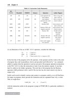
We can transform the timing diagram into a drum sequence requirement. Taking each drum
sequence step to take 5 s gives the requirement diagram shown in Table 10.1. Thus at step 1
we require output 1 to be switched on and to remain on until step 2. At step 2 we require
output 2 to be switched on and remain on until step 4. At step 3 we require output 3 to be
switched on and remain on until step 5. At step 5 we require output 4 to be switched on and
remain on until step 6.
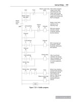
With a PLC such as a Toshiba, the sequencer is set up by switching on the Step Sequence
Initialize (STIZ) function block R500 (Figure 10.15). This sets up the program for step 1 and
0 5 10 15 20 25 30
Outputs
1
2
3
4
Time in seconds
Figure 10.14: Timing diagram.
Table 10.1: Sequence Requirements
Step Time (s) Output 1 Output 2 Output 3 Output 4
000000
151000
2100 1 00
3150 1 10
4200 0 10
5250 0 11
6300 0 00
www.newnespress.com
Counters 249
R501. This relay then switches on output Y020. The next step is the switching on of R502.
This switches on the output Y021 and a on-delay timer so that R503 is not switched on until the
timer has timed out. Then R503 switches on Y022 as well as the next step in the sequence.
With the Allen-Bradley form of PLC the sequencer is programmed using a sequence of
binary words in the form of the outputs required, such as those listed in Table 10.1. Thus we
would have the following binary word sequence put into the program using the programming
device. We have seven steps and four outputs.
Step 1 0000
Step 2 0001
Step 3 0010
Step 4 0110
Step 5 0100
Step 6 0101
Step 7 0000
Output 4
Output 3
Output 2
Output 1
X000 to switch on sequencer
STIZ R500
R501R500
R502R501
R501
Y020
R502
TON
T000
R503
Y022R503
R504R503
and so on
R502
Y021
Figure 10.15: Sequencer with a Toshiba PLC.
www.newnespress.com
250 Chapter 10
The term sequencer output (SQO) is used by Allen-Bradley for the output instruction that
uses a file or an array to control various output devices. As an illustration, Figure 10.16
shows a basic Allen-Bradley ladder program using such a sequencer. The timer is started by
an input to I:012/1 and has a preset time of 30 s. It is reset by its DN bit. The DN bit also
increments the SQO instruction to the next output word. Thus the sequencer is incremented
every 30 s. The location of the data for the words is given by FILE, which gives the starting
address for the registers in which the binary data for each step is stored. Sometimes the
sequencer is not required to operate on the entire word, so MASK gives the bit pattern that
masks off certain bits so they are not controlled by the sequencer. Thus we could have a
MASK word of:
1110011011111110
and so, because bits 1, 9, 12, and 13 are 0, these bits in the sequencer words are not changed.
SOURCE is the address of the input word or file for an SQC, and DESTINATION is the
address of the output word or file. CONTROL is the address that contains parameters with
control information. LENGTH is the number of steps of the sequencer file. POSITION is the
step in the sequencer file from/to which the instruction moves data.
Summary
Counters are provided as built-in elements in PLCs and allow the number of occurrences of
input signals to be counted. Down-counters count down from the preset value to zero, that is,
events are subtracted from the set value. When the counter reaches the zero value, its contacts
change state. Up-counters count from zero up to the preset value, that is, events are added
EN
DN
DN
CU
DN
Start
I:012/01
DN
TIMER ON DELAY
TIMER T4.0
TON
TIME BASE 1.0
PRESET 30
ACCUM 0
SQO
SQO increment
T4:0
SEQUENCER OUTPUT
FILE
Mask
DEST
CONTROL
LENGTH
POSITION
Timer
reset
T4:0
Figure 10.16: Allen-Bradley sequencer.
www.newnespress.com
Counters 251
until the number reaches the preset value. When the counter reaches the set value, its contacts
change state. Some PLCs offer the facility for both down- and up-counting.
The PLC sequencer consists of a master counter that has a range of preset counts
corresponding to the various steps; so as it progresses through the count, when each preset
count is reached it can be used to control outputs.
Problems
Problems 1 through 19 have four answer options: A, B, C, or D. Choose the correct answer
from the answer options. Problems 1 through 3 refer to Figure 10.17, which shows a ladder
diagram with a down-counter, two inputs (In 1 and In 2), and an output (Out 1).
1. Decide whether each of these statements is true (T) or false (F). For the ladder diagram
shown in Figure 10.17, when the counter is set to 5, there is an output from Out 1 every
time:
(i) In 1 has closed 5 times.
(ii) In 2 has closed 5 times.
A. (i) T (ii) T
B. (i) T (ii) F
C. (i) F (ii) T
D. (i) F (ii) F
2. Decide whether each of these statements is true (T) or false (F). For the ladder diagram
shown in Figure 10.17:
(i) The first rung gives the condition required to reset the counter.
(ii) The second rung gives the condition required to generate pulses to be counted.
A. (i) T (ii) T
B. (i) T (ii) F
C. (i) F (ii) T
D. (i) F (ii) F
In 1 Counter
RST
CounterIn 2
Counter Out 1
First rung
Second rung
Third rung
Figure 10.17: Diagram for Problems 1 through 3.
www.newnespress.com
252 Chapter 10
3. Decide whether each of these statements is true (T) or false (F). In Figure 10.17, when
there is an input to In 1:
(i) The counter contacts in the third rung close.
(ii) The counter is ready to start counting the pulses from In 2.
A. (i) T (ii) T
B. (i) T (ii) F
C. (i) F (ii) T
D. (i) F (ii) F
Problems 4 and 5 refer to the following program instruction list involving a down-counter:
LD X400
RST C460
LD X401
OUT C460
K5
LD 460
OUT Y430
4. Decide whether each of these statements is true (T) or false (F). Every time there is an
input to X401:
(i) The count accumulated by the counter decreases by 1.
(ii) The output is switched on.
A. (i) T (ii) T
B. (i) T (ii) F
C. (i) F (ii) T
D. (i) F (ii) F
5. Decide whether each of these statements is true (T) or false (F). When there is an input to
X400, the counter:
(i) Resets to a value of 5.
(ii) Starts counting from 0.
A. (i) T (ii) T
B. (i) T (ii) F
C. (i) F (ii) T
D. (i) F (ii) F
Problems 6 and 7 refer to the following program instruction list involving a counter C0:
A I0.0
CD C0
LKC 5
A I0.1
RC0
Q 2.00
www.newnespress.com
Counters 253
6. Decide whether each of these statements is true (T) or false (F). Every time there is an
input to I0.0:
(i) The count accumulated by the counter decreases by 1.
(ii) The output is switched on.
A. (i) T (ii) T
B. (i) T (ii) F
C. (i) F (ii) T
D. (i) F (ii) F
7. Decide whether each of these statements is true (T) or false (F). When there is an input to
I0.1, the counter:
(i) Resets to a value of 5.
(ii) Starts counting from 0.
A. (i) T (ii) T
B. (i) T (ii) F
C. (i) F (ii) T
D. (i) F (ii) F
Problems 8 and 9 refer to Figure 10.18, which shows a down-counter C460 controlled by two
inputs X400 and X401, with an output from Y430.
8. Decide whether each of these statements is true (T) or false (F). When there is an input to
X400, the counter:
(i) Resets to a value of 0.
(ii) Starts counting.
A. (i) T (ii) T
B. (i) T (ii) F
C. (i) F (ii) T
D. (i) F (ii) F
X400
X401
C460
RESET
OUT
C460
K10
Y430
Figure 10.18: Diagram for Problems 8 and 9.
www.newnespress.com
254 Chapter 10
9. Decide whether each of these statements is true (T) or false (F). Every time there is an
input to X401, the counter:
(i) Gives an output from Y430.
(ii) Reduces the accumulated count by 1.
A. (i) T (ii) T
B. (i) T (ii) F
C. (i) F (ii) T
D. (i) F (ii) F
Problems 10 through 12 refer to Figure 10.19, which shows a ladder diagram involving a
counter C460, inputs X400 and X401, internal relays M100 and M101, and an output Y430.
10. Decide whether each of these statements is true (T) or false (F). For the output Y430:
(i) It switches on with the tenth pulse to X400.
(ii) It switches off at the start of the eleventh pulse to X400.
A. (i) T (ii) T
B. (i) T (ii) F
C. (i) F (ii) T
D. (i) F (ii) F
RESET
C460
K10
OUT
X400 M101 M100
X400 M101
C460
X401
M100
Y430 M100
C460
Y430
Figure 10.19: Diagram for Problems 10 through 12.
www.newnespress.com
Counters 255
11. Decide whether each of these statements is true (T) or false (F). When there is an input to
X400:
(i) The internal relay M100 is energized.
(ii) The internal relay M101 is energized.
A. (i) T (ii) T
B. (i) T (ii) F
C. (i) F (ii) T
D. (i) F (ii) F
12. Decide whether each of these statements is true (T) or false (F). There is an output from
Y430 as long as:
(i) The C460 contacts are closed.
(ii) Y430 gives an output and M100 is energized.
A. (i) T (ii) T
B. (i) T (ii) F
C. (i) F (ii) T
D. (i) F (ii) F
13. Decide whether each of these statements is true (T) or false (F). Figure 10.20 shows a
counter program in Siemens format. After 10 inputs to I0.0:
(i) The lamp comes on.
(ii) The motor starts.
A. (i) T (ii) T
B. (i) T (ii) F
C. (i) F (ii) T
D. (i) F (ii) F
Problems 14 and 15 refer to Figure 10.21, which shows a Siemens program involving an
up- and down-counter.
I0.0
CU
PV10
Lamp
Q2.0
Q2.0 Motor
R
Q
S_CU
Figure 10.20: Diagram for Problem 13.
www.newnespress.com
256 Chapter 10
14. Decide whether each of these statements is true (T) or false (F). When the count is less
than 50 in Figure 10.21:
(i) There is an output from Q2.0.
(ii) There is an output from Q2.1.
A. (i) T (ii) T
B. (i) T (ii) F
C. (i) F (ii) T
D. (i) F (ii) F
15. Decide whether each of these statements is true (T) or false (F). When the count reaches
50 in Figure 10.21:
(i) There is an output from Q2.0.
(ii) There is an output from Q2.1.
A. (i) T (ii) T
B. (i) T (ii) F
C. (i) F (ii) T
D. (i) F (ii) F
Problems 16 and 17 refer to Figure 10.22, which shows an Allen-Bradley program involving
a count-up counter.
16. For the program shown in Figure 10.22, the counter is reset when:
A. The count reaches 5.
B. The count passes 5.
I0.0
I0.1
F0.0
I0.2
50
C0
CU
CD
S
PV
R
Q
Q2.0
Q2.0
Q2.1
Figure 10.21: Diagram for Problems 14 and 15.
www.newnespress.com
Counters 257
C. There is an input to I:012/01.
D. There is an input to I:012/02.
17. Decide whether each of these statements is true (T) or false (F). For the program shown
in Figure 10.22, there is an output at O:013/01 when:
(i) There is an input to I:012/01.
(ii) There is an output from the count-up done bit DN.
A. (i) T (ii) T
B. (i) T (ii) F
C. (i) F (ii) T
D. (i) F (ii) F
Problems 18 and 19 refer to Figure 10.23, which shows an Allen-Bradley program involving
a count-up counter.
CTU
COUNT UP
COUNTER C5:0
PRESET 5
ACCUM 0
I:012/01
CU
DN
C5:0 DN O:013/01
I:012/02
C5:0
RES
Figure 10.22: Diagram for Problems 16 and 17.
CTU
COUNT UP
COUNTER C5:1
PRESET 5
ACCUM 0
I:012/01
CU
DN
O:013/01
C5:1 DN
C5:1
RES
C5:1 CU
O:013/02
I:012/02
Figure 10.23: Diagram for Problems 18 and 19.
www.newnespress.com
258 Chapter 10
18. Decide whether each of these statements is true (T) or false (F). When there is a single
pulse input to I:012/01 in Figure 10.23:
(i) Output O:013/01 is switched on.
(ii) Output O:013/02 is switched on.
A. (i) T (ii) T
B. (i) T (ii) F
C. (i) F (ii) T
D. (i) F (ii) F
19. Decide whether each of these statements is true (T) or false (F). When the fifth pulse
input occurs to I:012/01 in Figure 10.23:
(i) Output O:013/01 is switched on.
(ii) Output O:013/02 is switched on.
A. (i) T (ii) T
B. (i) T (ii) F
C. (i) F (ii) T
D. (i) F (ii) F
20. Devise ladder programs for systems that will carry out the following tasks:
(a) Give an output after a photocell sensor has given 10 pulse input signals as a result of
detecting 10 objects passing in front of it.
(b) Give an output when the number of people in a store reaches 100, there continually
being people entering and leaving the store.
(c) Show a red light when the count is less than 5 and a green light when it is equal to or
greater than 5.
(d) Count 10 objects passing along a conveyor belt and close a deflecting gate when that
number have been deflected into a chute, allowing a time of 5 s between the tenth
object being counted and closing the deflector.
(e) Determine the number of items on a conveyor belt at any particular time by counting
those moving onto the belt and those leaving and give an output signal when the
number on the belt reaches 100.
Lookup Tasks
21. Look up the counters available with a particular range of PLCs.
22. Select, from manufacturer’s data sheets, possible sensors and a PLC that could be used to
control the counting of nontransparent objects moving along a conveyor belt.
www.newnespress.com
Counters 259
CHAPTER 11
Shift Registers
The term register is used for an electronic device in which data can be stored. An internal
relay (see Chapter 7) is such a device. The shift register is a number of internal relays
grouped together that allow stored bits to be shifted from one relay to another. This chapter is
about shift registers and how they can be used when a sequence of operations is required or to
keep track of particular items in a production system.
11.1 Shift Registers
A register is a number of internal relays grouped together, normally 8, 16, or 32. Each
internal relay is either effectively open or closed, these states being designated 0 and 1. The
term bit is used for each such binary digit. Therefore, if we have eight internal relays in the
register, we can store eight 0/1 states. Thus we might have, for internal relays:
12345678
and each relay might store an on/off signal such that the state of the register at some instant is:
10110010
that is, relay 1 is on, relay 2 is off, relay 3 is on, relay 4 is on, relay 5 is off, and so on. Such
an arrangement is termed an 8-bit register. Registers can be used for storing data that
originate from input sources other than just simple, single on/off devices such as switches.
With the shift register it is possible to shift stored bits. Shift registers require three inputs: one
to load data into the first location of the register, one as the command to shift data along by
one location, and one to reset or clear the register of data. To illustrate this idea, consider the
following situation where we start with an 8-bit register in the following state:
10110010
Suppose we now receive the input signal 0. This is an input signal to the first internal relay.
©
2009 Elsevier Ltd. All rights reserved.
doi: 10.1016/B978-1-85617-751-1.00011-2
261
!
Input 0
10110010
If we also receive the shift signal, the input signal enters the first location in the register, and
all the bits shift along one location. The last bit overflows and is lost.
01011001
Overflow 0
!
Thus a set of internal relays that were initially on, off, on, on, off, off, on, off are now off, on,
off, on, on, off, off, on.
The grouping together of internal relays to form a shift register is done automatically by a
PLC when the shift register function is selected. With the Mitsubishi PLC, this is done using
the programming code SFT (shift) against the internal relay number that is to be the first in
the register array. This then causes a block of relays, starting from that initial number, to be
reserved for the shift register.
11.2 Ladder Programs
Consider a 4-bit shift register and how it can be represented in a ladder program
(Figure 11.1a). The input In 3 is used to reset the shift register, that is, put all the values at 0.
The input In 1 is used to input to the first internal relay in the register. The input In 2 is used
to shift the states of the internal relays along by one. Each of the internal relays in the
register, that is, IR 1, IR 2, IR 3, and IR 4, is connected to an output, these being Out 1,
Out 2, Out 3, and Out 4.
Suppose we start by supplying a momentary input to In 3. All the internal relays are then
set to 0 and so the states of the four internal relays IR 1, IR 2, IR 3, and IR 4 are 0, 0, 0, 0.
When In 1 is momentarily closed, there is a 1 input into the first relay. Thus the states of
the internal relays IR 1, IR 2, IR 3, and IR 4 are now 1, 0, 0, 0. The IR 1 contacts close
and we thus end up with an output from Out 1. If we now supply a momentary input to
In 2, the 1 is shifted from the first relay to the second. The states of the internal relays are
now 0, 1, 0, 0. We now have no input from Out 1 but an output from Out 2. If we supply
another momentary input to In 2, we shift the states of the relays along by one location
to give 0, 0, 1, 0. Outputs Out 1 and Out 2 are now off, but Out 3 is on. If we supply another
momentary input to In 2, we again shift the states of the relays along by one and have
0, 0, 0, 1. Thus now Out 1, Out 2, and Out 3 are off and Out 4 has been switched on.
When another momentary input is applied to In 2, we shift the states of the relays along
by one and have 0, 0, 0, 0, with the 1 overflowing and being lost. All the outputs are then
off. Thus the effect of the sequence of inputs to In 2 has been to give a sequence of
www.newnespress.com
262 Chapter 11
outputs Out 1, followed by Out 2, followed by Out 3, followed by Out 4. Figure 11.1b
shows the sequence of signals.
Figure 11.2 shows the Mitsubishi version of the preceding ladder program and the associated
instruction list. Instead of the three separate outputs for reset, output, and shift, the
Mitsubishi shift register might appear in a program as a single function box, as shown in
the figure. With the Mitsubishi shift register, the M140 is the address of the first relay
in the register.
Figure 11.3 shows a shift register ladder program for a Toshiba PLC. With the Toshiba, R016
is the address of the first relay in the register. The (08) indicates that there are eight such relays.
D is used for the data input, S for shift input, E for enable or reset input, and Q for output.
Figure 11.4 shows the IEC 1131-3 standard symbol for a shift register. The value to be
shifted is at input IN and the number of places it is to be shifted is at input N.
Figure 11.5a shows the Siemens symbol for a shift register. If the enable input EN is 1,
the shift function is executed and ENO is then 1. If EN is 0, the shift function is not executed and
In 1
In 2
In 3
IR 1
IR 2
IR3
Out 1
Out 2
Out 3
IR4 Out 4
RST
OUT
SFT
Shift Register
Internal registers
IR 1, IR 2, IR 3, IR 4
Output controlled
by first internal relay
in register
Output controlled
by second internal relay
in register
Output controlled
by third internal relay
in register
Output controlled
by fourth internal relay
in register
END
In 1
In 2
Out 1
Out 2
Out 3
Out 4
Time
Time
Time
Time
Time
(a) (b)
Figure 11.1: The shift register.
www.newnespress.com
Shift Registers 263
ENO is 0. The shift function SHL_W shifts the contents of the word variable at input IN bit by
bit to the left the number of positions specified by the input at N. The shifted word output is at
OUT. Figure 11.5b shows the Allen-Bradley PLC 5 and SLC 500 symbols for shift registers.
The FILE gives the address of the bit array that is to be shifted. CONTROL gives the address
of control bits such as bit 15 (EN) as a 1 when the instruction is enabled, bit 13 (DN) as a 1
when the bits have shifted, and bit 11 (ER) as a 1 when the length is negative, and bit 10 (UL)
stores the state of the bit that was shifted out of the range of bits. BIT ADDRESS is the address
of the data to be shifted. LENGTH is the number of bits in the array to be shifted.
11.2.1 A Sequencing Application
Consider the requirement for a program for two double-solenoid cylinders, the arrangement
as shown in Figure 11.6a, to give the sequence A þ ,Bþ, A–, B–. Figure 11.6b shows a
program to achieve this sequence by the use of a shift register.
11.2.2 Keeping Track of Items
The preceding indicates how a shift register can be used for sequencing. Another application
is to keep track of items. For example, a sensor might be used to detect faulty items moving
along a conveyor and keep track of them so that when they reach the appropriate point, a
RST
OUT
SFT
X400 M140
X401
X402
M140 Y430
M141 Y431
M142 Y432
M143 Y433
END
LD
LD
SFT
LD
RST
LD
OUT
LD
OUT
LD
OUT
LD
OUT
X400
M140
X401
M140
X402
M140
M140
Y430
M141
Y431
M142
Y432
M143
Y433
OUT
END
RST
OUT
SFT
M140
Representation of the
three shift register elements
in a single box
Figure 11.2: Mitsubishi shift register program.
www.newnespress.com
264 Chapter 11
reject mechanism is activated to remove them from the conveyor. Figure 11.7 illustrates this
arrangement and the type of ladder program that might be used.
Each time a faulty item is detected, a pulse signal occurs at input X400. This enters a 1 into
the shift register at internal relay M140. When items move, whether faulty or not, there is a
pulse input at X401. This shifts the 1 along the register. When the 1 reaches internal relay
X007
X000
X001
R016 Y020
R017 Y021
R018 Y022
R019 Y023
R01A Y024
R01B
Y025
R01C
Y026
D
S
E
Q
(08)
R016
R01D Y027
END
Figure 11.3: Toshiba shift register.
www.newnespress.com
Shift Registers 265
M144, it activates the output Y430 and the rejection mechanism removes the faulty item
from the conveyor. When an item is removed, it is sensed and an input to X403 occurs.
This is used to reset the mechanism so that no further items are rejected until the rejection
signal reaches M144. It does this by giving an output to internal relay M100, which latches
the X403 input and switches the rejection output Y430 off. This represents just the basic
elements of a system. A practical system would include further internal relays to make
certain that the rejection mechanism is off when good items move along the conveyor belt as
well as to disable the input from X400 when the shifting is occurring.
Summary
The term register is used for an electronic device in which data can be stored. The shift
register is a number of internal relays grouped together that allow stored bits to be shifted
from one relay to another. With the shift register it is possible to shift stored bits. Shift
registers require three inputs: one to load data into the first location of the register, one as the
command to shift data along by one location, and one to reset or clear the register of data.
The grouping together of internal relays to form a shift register is done automatically by a
PLC when the shift register function is selected.
IN
N
ANY_BIT
ANY
SHL
Shift left
IN
N
SHR
Shift right
ANY_INT
ANY_BIT
ANY_INT
ANY
Figure 11.4: IEC 1131-3 shift register symbols.
EN
IN
N
ENO
OUT
SHL_W
Shift left a word
EN
IN
N
ENO
OUT
SHR_W
Shift right a word
(a)
BSL
BIT SHIFT LEFT
FILE
CONTROL
BIT ADDRESS
LENGTH
EN
DN
BSR
BIT SHIFT RIGHT
FILE
CONTROL
BIT ADDRESS
LENGTH
EN
DN
Shift left a bit Shift ri
g
ht a bit(b)
Figure 11.5: Shift register symbols: (a) Siemens, and (b) Allen-Bradley.
www.newnespress.com
266 Chapter 11
Problems
Problems 1 through 9 have four answer options: A, B, C, or D. Choose the correct answer
from the answer options. Problems 1 through 5 concern a 4-bit shift register involving
internal relays IR 1, IR 2, IR 3, and IR 4, which has been reset to 0, 0, 0, 0.
1. When there is a pulse 1 input to the OUT of the shift register, the internal relays in the
shift register show:
A. 0001
B. 0010
C. 0100
D. 1000
Start
Restart
IR 1
IR 2
IR 3
A+
B+
A–
IR 4
B–
RST
OUT
SFT
IR
IR
a+
IR
b+
a–
b–
END
Shift for
IR 1, IR 2,
IR 3, IR 4
Activation of any
limit switch
produces a pulse
which shifts the
OUT pulse along
by 1 bit. Thus
a+ gives 0100,
b+ gives 0010,
a– gives 0001
and b– gives 0000
This gives an input
of 1 to the register
to give the state of
the registers as 1000
Register
Register
Register
B
b–
b+
B+
B–
A
a–
a+
A+
A–
(a)
(b)
Figure 11.6: Sequencing cylinders.
www.newnespress.com
Shift Registers 267
2. Following a pulse input of 1 to the OUT of the shift register, there is a pulse input to
SHIFT. The internal relays then show:
A. 0001
B. 0010
C. 0100
D. 1000
3. With a continuous input of 1 to the OUT of the shift register, there is a pulse input to
SHIFT. The internal relays then show:
A. 0011
B. 0110
C. 1100
D. 0010
4. With a continuous input of 1 to the OUT of the shift register, there are two pulse inputs to
SHIFT. The internal relays then show:
A. 0001
B. 0010
C. 1100
D. 1110
OUT
SFT
RST
X400
M140
M140
M140
M140
X401
X402
M144X403
M100
M144 M100
Y430
Output to
activate
rejection
mechanism
Resetting afte
r
rejection
M100
(b)
END
Items for
packaging
Faulty items
deflected from
conveyor
Faulty items
detected
(a)
Figure 11.7: Keeping track of faulty items.
www.newnespress.com
268 Chapter 11
5. With a pulse input of 1 to the OUT of the shift register, there is a pulse input to SHIFT,
followed by a pulse input to RESET. The internal relays then show:
A. 0000
B. 0010
C. 0100
D. 1000
Problems 6 through 9 concern Figure 11.8, which shows a 4-bit shift register with internal
relays IR 1, IR 2, IR 3, and IR 4, with three inputs (In 1, In 2, and In 3) and four outputs (Out
1, Out 2, Out 3, and Out 4).
6. Decide whether each of these statements is true (T) or false (F). When there is a pulse
input to In 1:
(i) The output Out 1 is energized.
(ii) The contacts of internal relay IR 1 close.
In 1
In 2
In 3
IR 1
IR 2
IR3
IR 4
Out 1
Out 2
Out 3
Out 4
RST
OUT
SFT
END
Figure 11.8: Diagram for Problems 6 through 9.
www.newnespress.com
Shift Registers 269
A. (i) T (ii) T
B. (i) T (ii) F
C. (i) F (ii) T
D. (i) F (ii) F
7. Decide whether each of these statements is true (T) or false (F). When there is a pulse
input to In 1 followed by a pulse input to SFT:
(i) Output Out 1 is energized.
(ii) Output Out 2 is energized.
A. (i) T (ii) T
B. (i) T (ii) F
C. (i) F (ii) T
D. (i) F (ii) F
8. Decide whether each of these statements is true (T) or false (F). To obtain outputs Out 1,
Out 2, Out 3, and Out 4 switching on in sequence and remaining on, we can have for
inputs:
(i) A pulse input to In 1 followed by three pulse inputs to SFT.
(ii) A continuous input to In 1 followed by three pulse inputs to SFT.
A. (i) T (ii) T
B. (i) T (ii) F
C. (i) F (ii) T
D. (i) F (ii) F
9. Initially: Out 1 off, Out 2 off, Out 3 off, Out 4 off
Next: Out 1 on, Out 2 off, Out 3 off, Out 4 off
Next: Out 1 off, Out 2 on, Out 3 off, Out 4 off
Next: Out 1 on, Out 2 off, Out 3 on, Out 4 off
The inputs required to obtain the preceding sequence are:
A. Pulse input to In 1 followed by pulse input to In 2.
B. Pulse input to In 1 followed by two pulses to In 2.
C. Pulse input to In 1 followed by pulse input to In 2, then by pulse input to In 1.
D. Pulse input to In 1 followed by pulse input to In 2, then by pulse inputs to In 1 and
In 2.
10. Devise ladder programs for systems to carry out the following tasks:
(a) A sequence of four outputs such that output 1 is switched on when the first event is
detected and remains on, output 2 is switched on when the second event is detected
and remains on, output 3 is switched on when the third event is detected and remains
on, output 4 is switched on when the fourth event is detected and remains on, and all
outputs are switched off when one particular input signal occurs.
www.newnespress.com
270 Chapter 11
(b) Control of a paint sprayer in a booth through which items pass on an overhead
conveyor so that the paint is switched on when a part is in front of the paint gun and
off when there is no part. The items are suspended from the overhead conveyor by
hooks; not every hook has an item suspended from it.
Lookup Tasks
11. Find out the details of shift registers available with PLCs from a particular range from a
specific manufacturer.
www.newnespress.com
Shift Registers 271
CHAPTER 12
Data Handling
Timers, counters, and individual internal relays are all concerned with the handling of
individual bits, that is, single on/off signals. Shift registers involve a number of bits with a
group of internal relays being linked (see Chapter 11). The block of data in the register is
manipulated. This chapter is about PLC operations involving blocks of data representing
a value; such blocks are called words. A block of data is needed if we are to represent
numbers rather than just a single on/off input. Data handling consists of operations
involving moving or transferring numeric information stored in one memory word location
to another word in a different location, comparing data values, and carrying out simple
arithmetic operations. For example, there might be the need to compare a numeric value
with a set value and initiate action if the actual value is less than the set value. This chapter is
an introductory discussion of such operations.
12.1 Registers and Bits
A register is where data can be stored (see Section 8.1 for an initial discussion of registers).
In a PLC there are a number of such registers. Each data register can store a binary word
of usually 8 or 16 bits. The number of bits determines the size of the number that can be
stored. The binary system uses only two symbols, 0 and 1 (see Chapter 3). Thus we might
have the 4-bit number 1111. This is the denary number, that is, the familiar number system
based on 10s, of 2
0
þ 2
1
þ 2
2
þ 2
3
¼ 1 þ 2 þ 4 þ 8 ¼ 15. Thus a 4-bit register can
store a positive number between 0 and 2
0
þ 2
1
þ 2
2
þ 2
3
or 2
4
À 1 ¼ 15. An 8-bit
register can store a positive number between 0 and 2
0
þ 2
1
þ 2
2
þ 2
3
þ 2
4
þ 2
5
þ 2
6
þ 2
7
or
2
8
À 1, that is, 255. A 16-bit register can store a positive number between 0 and 2
16
À 1,
that is, 65,535.
Thus a 16-bit word can be used for positive numbers in the range 0 to 65,535. If negative
numbers are required, the most significant bit is used to represent the sign, a 1 representing
a negative number and a 0 a positive number; the format used for negative numbers is two’s
complement. Two’s complement is a way of writing negative numbers so that when we add,
say, the signed equivalent of þ5 and –5, we obtain 0. Thus in this format, 1011 represents the
negative number À5 and 0101 the positive number þ5; 1011 þ 0101 ¼ (1)0000 with the (1)
for the 4-bit number being lost. See Chapter 3 for further discussion.
©
2009 Elsevier Ltd. All rights reserved.
doi: 10.1016/B978-1-85617-751-1.00012-4
273
The binary coded decimal (BCD) format is often used with PLCs when they are connected to
devices such as digital displays. With the natural binary number there is no simple link
between the separate symbols of a denary number and the equivalent binary number. You
have to work out the arithmetic to decipher one number from the other. With the BCD
system, each denary digit is represented, in turn, by a 4-bit binary number (four is the
smallest number of binary bits that gives a denary number greater than 10, that is, 2
n
> 10).
To illustrate this idea, consider the denary number 123. The 3 is represented by the 4-bit
binary number 0011, the 2 by the 4-bit number 0010, and the 1 by 0001. Thus the BCD
number of 123 is 0001 0010 0011. BCD is a convenient system for use with external devices
that are arranged in denary format, such as decade switches (thumbwheel switches) and
digital displays. Then four binary bits can be used for each denary digit. PLCs therefore often
have inputs or outputs that can be programmed to convert BCD from external input devices
to the binary format needed inside the PLC and from the binary format used internally in the
PLC to BCD for external output devices (see Section 12.3).
The thumbwheel switch is widely used as a means of inputting BCD data manually into a
PLC. It has four contacts that can be opened or closed to give the four binary bits to represent
a denary number (Figure 12.1). The contacts are opened or closed by rotating a wheel using
one’s thumb. By using a number of such switches, data can be input in BCD format.
12.2 Data Handling
The following are examples of data-handling instructions to be found with PLCs.
12.2.1 Data Movement
For moving data from one location or register to another, Figure 12.2 illustrates a common
practice of using one rung of a ladder program for each move operation, showing the form
used by three manufacturers: Mitsubishi, Allen-Bradley, and Siemens. For the rung shown,
3
+V
Outputs
Switch outputsPosition
0
1
2
3
4
5
6
7
8
9
0 0 0 0
0 0 0 1
0 0 1 0
0 0 1 1
0 1 0 0
0 1 0 1
0 1 1 0
0 1 1 1
1 0 0 0
1 0 0 1
0 = switch open 1 = switch closed
Figure 12.1: Thumbwheel switch.
www.newnespress.com
274 Chapter 12
when there is an input to | | in the rung, the move occurs from the designated source address
to the designated destination address. For data handling with these PLCs, the typical ladder
program data-handling instruction contains the data-handling instruction, the source (S)
address from where the data is to be obtained, and the destination (D) address to where it
is to be moved. The approach that is used by some manufacturers, such as Siemens, is to
regard data movement as two separate instructions, loading data from the source into an
accumulator and then transferring the data from the accumulator to the destination.
Figure 12.2c shows the Siemens symbol for the MOVE function. The data is moved from
the IN input to the OUT output when EN is enabled.
Data transfers might be to move a preset value to a timer or counter, or a time or counter
value to some register for storage, or data from an input to a register or a register to output.
Figure 12.3 shows the rung, in the Allen-Bradley format, that might be used to transfer a
number held at address N7:0 to the preset of timer T4:6 when the input conditions for that
rung are met. A data transfer from the accumulated value in a counter to a register would
have a source address of the form C5:18.ACC and a destination address of the form N7:0. A
data transfer from an input to a register might have a source address of the form I:012 and a
destination address of the form N7:0. A data transfer from a register to an output might have
a source address of the form N7:0 and a destination address of the form O:030.
MOV S
D1
D2
Source address
Destination address
(a)
MOV
MOVE
SOURCE N7:0
DEST N7.2
(b)
MOVE
EN ENO
IN OUT
(c)
D
Figure 12.2: Data movement: (a) Mitsubishi, (b) Allen-Bradley, and (c) Siemens.
MOVE
SOURCE N7:0
DEST T4:6.PRE
MOV
Figure 12.3: Moving number to timer preset.
www.newnespress.com
Data Handling 275