Programmable logic controllers 5ed P5
Bạn đang xem bản rút gọn của tài liệu. Xem và tải ngay bản đầy đủ của tài liệu tại đây (1.62 MB, 50 trang )
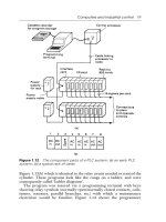
TimerStart
MCR
a–
b–
b–
a+
a+ b+
a– b+
Timer
END
Master control relay
switches on the
following rungs
With both cylinders
retracted, cylinder
A extends, latching
the limit switches
With A extended and
B retracted, cylinder
B extends, latching the
limit switches
With A and B both
extended, the internal
relay is energized. This
switches off solenoid
A+ and so solenoid A
retracts
When A has retracted,
cylinder B still extended,
activating the internal
relay switches the
timer on. After the set
time the system is
switched off and B
retracts
Start switch energizes
master control relay
and latches start. No
matter what the state
of the limit switches, the
system will not start until
MCR is energized
Master control relay
MCR
Master
control
relay
Master control relay
MCR
Internal relay
IR
Internal relay
IR
Internal relay
IR
Limit switches
Limit switches
Solenoid
B+
Solenoid
A+
Internal
relay
IR
Limit switches
Solenoid
A+
Limit switches
Solenoid
B+
Master control
relay MCR
Figure 7.29: A ladder program.
www.newnespress.com
Internal Relays 199
A MCR is able to turn on or off a section of a ladder program up to the point at which the
master control relay is reset.
Problems
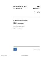
Problems 1 through 23 have four answer options: A, B, C, or D. Choose the correct answer
from the answer options. Problems 1 through 3 refer to Figure 7.30, which shows a ladder
diagram with an internal relay (designated IR 1), two inputs (In 1 and In 2), and an output
(Output 1).
1. Decide whether each of these statements is true (T) or false (F). For the ladder diagram
shown in Figure 7.30, there is an output from output 1 when:
(i) There is just an input to In 1.
(ii) There is just an input to In 2.
A. (i) T (ii) T
B. (i) T (ii) F
C. (i) F (ii) T
D. (i) F (ii) F
2. Decide whether each of these statements is true (T) or false (F). For the ladder diagram
shown in Figure 7.30, there is an output from output 1 when:
(i) There is an input to In 2 and a momentary input to In 1.
(ii) There is an input to In 1 or an input to In 2.
A. (i) T (ii) T
B. (i) T (ii) F
C. (i) F (ii) T
D. (i) F (ii) F
In 2 IR 1
IR 1
IR 1
In 1
Output 1
Figure 7.30: Diagram for Problems 1, 2, and 3.
www.newnespress.com
200 Chapter 7
3. Decide whether each of these statements is true (T) or false (F). For the ladder diagram
shown in Figure 7.30, the internal relay:
(i) Switches on when there is just an input to In 1.
(ii) Switches on when there is an input to In 1 and to In 2.
A. (i) T (ii) T
B. (i) T (ii) F
C. (i) F (ii) T
D. (i) F (ii) F
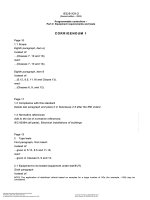
Problems 4 through 6 refer to Figure 7.31, which shows a ladder diagram involving internal
relays IR 1 and IR 2, inputs In 1, In 2, In 3, and In 4, and output Output 1.
4. Decide whether each of these statements is true (T) or false (F). For the ladder diagram
shown in Figure 7.31, the internal relay IR 1 is energized when:
(i) There is an input to In 1.
(ii) There is an input to In 3.
A. (i) T (ii) T
B. (i) T (ii) F
C. (i) F (ii) T
D. (i) F (ii) F
5. Decide whether each of these statements is true (T) or false (F). For the ladder diagram
shown in Figure 7.31, the internal relay IR 2 is energized when:
(i) Internal relay IR 1 is energized.
(ii) Input 4 is energized.
A. (i) T (ii) T
B. (i) T (ii) F
In 2 IR 1
IR 1
Output 1
IR2
In 3
In 1
In 4
IR 2
Figure 7.31: Diagram for Problems 4, 5, and 6.
www.newnespress.com
Internal Relays 201
C. (i) F (ii) T
D. (i) F (ii) F
6. Decide whether each of these statements is true (T) or false (F). For the ladder diagram
shown in Figure 7.31, there is an output from Output 1 when:
(i) There are inputs to only In 1, In 2, and In 4.
(ii) There are inputs to only In 3 and In 4.
A. (i) T (ii) T
B. (i) T (ii) F
C. (i) F (ii) T
D. (i) F (ii) F
7. Which one of the programs in Figure 7.32 can obtain an output from Out 1 when just
input In 1 occurs?
8. Which one of the programs in Figure 7.33 will give an output from Out 1 in the same
program scan as there is an input to In 1?
Problems 9 and 10 refer to Figure 7.34, which shows a ladder diagram involving a battery-
backed relay IR 1, two inputs (In 1 and In 2), and an output (Output 1).
9. Decide whether each of these statements is true (T) or false (F). For the ladder diagram
shown in Figure 7.34, there is an output from Output 1 when:
(i) There is a short duration input to In 1.
(ii) There is no input to In 2.
A. (i) T (ii) T
B. (i) T (ii) F
In 2 IR 1
IR 1
Output 1
In2
In 1
A
In 2
IR 1
IR 1
Output 1
In2
In 1
B
In 2 IR 1
IR 1
Output 1
In2
In 1
C
In 2 IR 1
IR 1
Output 1
In2
In 1
D
Figure 7.32: Diagram for Problem 7.
www.newnespress.com
202 Chapter 7
C. (i) F (ii) T
D. (i) F (ii) F
10. Decide whether each of these statements is true (T) or false (F). For the ladder diagram
shown in Figure 7.34:
(i) The input In 1 is latched by the internal relay so that the internal relay IR 1 remains
energized, even when the input In 1 ceases.
Out 1
IR 1In 1
IR 1
END
Out 1
IR 1
In 1
IR 1
END
Out 1
IR 1
In 1
IR 1
END
Out 1
IR 1
In 1
In 1
END
IR 1
IR 1
A
B
C
D
Figure 7.33: Diagram for Problem 8.
In 2
IR 1
Battery-backed
IR 1
Output 1
IR 1
In 1
Figure 7.34: Diagram for Problems 9 and 10.
www.newnespress.com
Internal Relays 203
(ii) Because the internal relay IR 1 is battery-backed, once there is an output from
Output 1, it will continue, even when the power is switched off, until there is an
input to In 2.
A. (i) T (ii) T
B. (i) T (ii) F
C. (i) F (ii) T
D. (i) F (ii) F
11. When the program instructions LD X100, PLS M400 are used for a ladder rung, the
internal relay M400 will:
A. Remain on even when the input to X100 ceases
B. Remain closed unless there is a pulse input to X100
C. Remain on for one program cycle when there is an input to X100
D. Remain closed for one program cycle after an input to X100
12. When the program instructions LDI X100, PLS M400 are used for a ladder rung, the
internal relay M400 will:
A. Remain on when the input to X100 ceases
B. Remain on when there is a pulse input to X100
C. Remain on for one program cycle when there is an input to X100
D. Remain on for one program cycle after the input to X100 ceases
13. A Mitsubishi ladder program has the program instructions LD X100, S M200, LD X101,
R M200, followed by other instructions for further rungs. There is the following
sequence: an input to the input X100, the input to X100 ceases, some time elapses, an
input to the input X101, the input to X101 ceases, followed by inputs to later rungs.
The internal relay M200 will remain on:
A. For one program cycle from the start of the input to X100
B. From the start of the input to X100 to the start of the input to X101
C. From the start of the input to X100 to the end of the input to X101
D. From the end of the input to X100 to the end of the input to X101
14. A Siemens ladder program has the program instructions A I0.0, S F0.0, A I0.1, R F0.0,
A F0.0, ¼ Q2.0, followed by other instructions for further rungs. There is the sequence:
an input to input I0.0, the input to I0.0 ceases, some time elapses, an input to input I0.1,
the input to I0.1 ceases, followed by inputs to later rungs. The internal relay F0.0 will
remain on:
A. For one program cycle from the start of the input to I0.0
B. From the start of the input to I0.0 to the start of the input to I0.1
C. From the start of the input to I0.0 to the end of the input to I0.1
D. From the end of the input to I0.0 to the end of the input to I0.1
www.newnespress.com
204 Chapter 7
15. A Telemecanique ladder program has the program instructions L I0,0, S O0,0, L I0,1,
R O0,0, followed by other instructions for further rungs. There is the following
sequence: an input to input I0,0, the input to I0,0 ceases, some time elapses, an input to
input I0,1, the input to I0,1 ceases, followed by inputs to later rungs. The internal relay
O0,0 will remain on:
A. For one program cycle from the start of the input to I0,0
B. From the start of the input to I0,0 to the start of the input to I0,1
C. From the start of the input to I0,0 to the end of the input to I0,1
D. From the end of the input to I0,0 to the end of the input to I0,1
16. An output is required from output Y430 that lasts for one cycle after an input to X100
starts. This can be given by a ladder program with the instructions:
A. LD X100, Y430
B. LD X100, M100, LD M100, Y430
C. LD X100, PLS M100, LD M100, Y430
D. LD X400, PLS M100, LDI M100, Y430
Problems 17 and 18 refer to Figure 7.35, which shows two versions of the same ladder
diagram according to two different PLC manufacturers. In Figure 7.35a, which uses Siemens
notation, I is used for inputs, F for internal relays, and Q for the output. In Figure 7.35b,
which uses Telemecanique notation, I is used for inputs and B for internal relays.
17. For the ladder diagram shown in Figure 7.35a, when there is an input to I0.0, the output
Q2.0:
A. Comes on and remains on for one cycle.
B. Comes on and remains on.
C. Goes off and remains off for one cycle.
D. Goes off and remains off.
I0.0 F0.1
F0.0
F0.1F0.0
I0.0
S
R
(a) (b)
Q2.0
B0
I0,0
B1
B0 B1
I0,0
B1
S
R
Figure 7.35: Diagram for Problems 17 and 18.
www.newnespress.com
Internal Relays 205
18. For the ladder diagram shown in Figure 7.35b, when there is an input to I0,0, the internal
relay B1:
A. Comes on and remains on for one cycle.
B. Comes on and remains on.
C. Goes off and remains off for one cycle.
D. Goes off and remains off.
Problems 19 and 20 refer to Figure 7.36, which shows a Toshiba ladder program with inputs
X000, X001, and X002, an output Y020, and a flip-flop R110.
19. Decide whether each of these statements is true (T) or false (F). For there to be an output
from Y020, there must be an input to:
(i) X000.
(ii) X001.
A. (i) T (ii) T
B. (i) T (ii) F
C. (i) F (ii) T
D. (i) F (ii) F
20. Decide whether each of these statements is true (T) or false (F). With an input to X000,
then:
(i) An input to X001 causes the output to come on.
(ii) An input to X002 causes the output to come on.
A. (i) T (ii) T
B. (i) T (ii) F
C. (i) F (ii) T
D. (i) F (ii) F
21. Decide whether each of these statements is true (T) or false (F). A master control relay
can be used to:
(i) Turn on a section of a program when certain criteria are met.
(ii) Turn off a section of a program when certain criteria are not met.
X000
X002
S
R
FF
R110
Y020X001
Figure 7.36: Diagram for Problems 19 and 20.
www.newnespress.com
206 Chapter 7
A. (i) T (ii) T
B. (i) T (ii) F
C. (i) F (ii) T
D. (i) F (ii) F
Problems 22 and 23 refer to Figure 7.37, which shows a ladder program in Allen-Bradley
format.
22. Decide whether each of these statements is true (T) or false (F). When there is an input to
I:010/01:
(i) An input to I:010/02 gives an output from O:010/00.
(ii) An input to I:010/03 gives an output from O:010/01.
A. (i) T (ii) T
B. (i) T (ii) F
C. (i) F (ii) T
D. (i) F (ii) F
23. Decide whether each of these statements is true (T) or false (F). When there is no input to
I:010/01:
(i) An input to I:010/02 gives no output from O:010/00.
(ii) An input to I:010/04 gives no output from O:010/02.
A. (i) T (ii) T
B. (i) T (ii) F
I:010/01
I:010/02
I:010/03
MCR
MCR
O:010/00
O:010/01
I:010/04
O:010/02
Figure 7.37: Diagram for Problems 22 and 23.
www.newnespress.com
Internal Relays 207
C. (i) F (ii) T
D. (i) F (ii) F
24. Devise ladder programs that can be used to:
(a) Maintain an output on, even when the input ceases and when there is a power failure
(b) Switch on an output for a time of one cycle following a brief input
(c) Switch on the power to a set of rungs
www.newnespress.com
208 Chapter 7
CHAPTER 8
Jump and Call
This chapter considers the jump instruction, which enables part of a program to be jumped over,
and the way in which subroutines in ladder programs can be called up. Subroutines enable
commonly occurring operations in a program to be repeatedly called up and used over again.
8.1 Jump
A function often provided with PLCs is the conditional jump. We can describe this as:
IF (some condition occurs) THEN
perform some instructions
ELSE
perform some other instructions
Such a facility enables programs to be designed such that if certain conditions are met,
certain events occur, and if they are not met, other events occur. Thus, for example, we might
need to design a system so that if the temperature is above 60
C a fan is switched on, and if
below that temperature no action occurs.
Thus, if the appropriate conditions are met, this function enables part of a ladder program to
be jumped over. Figure 8.1 illustrates this concept in a general manner. When there is an
input to Input 1, its contacts close and there is an output to the jump relay. This then results in
the program jumping to the rung in which the jump end occurs and skipping the intermediate
program rungs. Thus, in this case, when there is an input to Input 1, the program jumps to
rung 4 and then proceeds with rungs 5, 6, and so on. When there is no input to Input 1, the
jump relay is not energized and the program then proceeds to rungs 2, 3, and so on.
Figure 8.2a shows the preceding ladder program in the form used by Mitsubishi. The jump
instruction is denoted by conditional jump (CJP) and the place to which the jump occurs
is denoted by end of jump (EJP). The condition that the jump will occur is that there is
an input to X400. When that happens, the rungs involving inputs X401 and X403 are ignored
and the program jumps to continue with the rungs following the end-jump instruction with
the same number as the start-jump instruction—in this case, EJP 700.
©
2009 Elsevier Ltd. All rights reserved.
doi: 10.1016/B978-1-85617-751-1.00008-2
209
With the Allen-Bradley PLC-5 format, the jump takes place from the jump instruction (JMP)
to the label instruction (LBL). The JMP instruction is given a three-digit number from 000
to 255 and the LBL instruction the same number. Figure 8.2b shows a ladder program in
this format.
With Siemens’ programs, conditional jumps are represented as shown in Figure 8.3, there
being a jump instruction JMP that is executed if the input is a 1 and another jump instruction
JMPN that is executed if the input is 0. The end of both instructions is the label DEST.
8.1.1 Jumps Within Jumps
Jumps within jumps are possible. For example, we might have the situation shown in
Figure 8.4. If the condition for jump instruction 1 is realized, the program jumps to
rung 8. If the condition is not met, the program continues to rung 3. If the condition for
Input 1
Jump end
Rung 1
Rung 2
Rung 3
Rung 4
etc.
Jump
Figure 8.1: Jump.
CJP 700
EJP 700
Input 1
X400
Input 2
X401
Input 3
X402
Output 1
Y430
Output 2
Y431
Jump between
these rungs
of the program
if Input 1 occurs
JMP
LBL
I:012/10
I:012/11
I:012/12
010
O:012/10
O:012/11
O:012/12
Jump if Input
I:012/10 occurs
Input
Label
010
Output
(a) (b)
Jump
Figure 8.2: Jump: (a) a Mitsubishi program, and (b) an Allen-Bradley program.
www.newnespress.com
210 Chapter 8
jump instruction 2 is realized, the program jumps to rung 6. If the condition is not met, the
program continues through the rungs.
Thus if we have an input to In 1, the rung sequence is rung 1, 8, and so on. If we have
no input to In 1 but we have an input to In 3, the rung sequence is 1, 2, 6, 7, 8, and so on.
If we have no input to In 1 and no input to In 3, the rung sequence is 1, 2, 3, 4, 5, 6, 7, 8, and
so on. The jump instruction enables different groups of program rungs to be selected,
depending on the conditions occurring.
8.2 Subroutines
Subroutines are small programs to perform specific tasks that can be called for use in larger
programs. The advantage of using subroutines is that they can be called repetitively to
JMP
Jump if
input 1
JMPN
Jump if
input 0
End of jump
DEST
Figure 8.3: Siemens’ jump instructions.
Rung 1
Rung 2
Rung 3
Rung 4
Rung 5
Rung 6
Rung 7
Rung 8
Jump 1
Jump 2
In 1
In 3
Jump 2 end
Jump 1 end
If In 1
If In 3
Figure 8.4: Jumps within jumps.
www.newnespress.com
Jump and Call 211
perform specific tasks without having to be written out in full in the larger program. Thus
with a Mitsubishi program we might have the situation shown in Figure 8.5a. When input
1 occurs, the subroutine P is called. This is then executed, the instruction SRET indicating its
end and the point at which the program returns to the main program.
With Allen-Bradley, subroutines are called by using a jump-to-subroutine (JSR) instruction,
the start of the subroutine being indicated by SBR and its end and point of return to the main
program by RET (Figure 8.5b). With other PLC manufacturers a similar format can be
adopted; they might use CALL to call up a subroutine block and RET to indicate the return
instruction to the main program.
8.2.1 Function Boxes
A function box approach can be used with programs and is particularly useful where there is
a library of subroutine functions to be called. A function box is defined as being part of a
program that is packaged so that it can be used a number of times in different parts of the
same program or different programs. Using such boxes enables programs to be constructed
from smaller, more manageable blocks. Each function box has input and output for
connection to the main program, is able to store values, and contains a piece of program code
Input 1
CALL P
Main program and
return point after
subroutine
Call to subroutine
conditional on Input 1
etc.
SRET
Subroutine
JSR
etc
Jump to subroutine
conditional on
Input 1
Main program
and return point
after subroutine
SBR
RET
Subroutine
End of subroutine
and return to main
program
(a) (b)
Input 1
End of subroutine
and return to main
program
END
END
; Subroutine
Figure 8.5: (a) Subroutine call with Mitsubishi PLC, (b) jump to subroutine call with
Allen-Bradley PLC.
www.newnespress.com
212 Chapter 8
that runs every time the box is used, processing the input to give the output. PLC
manufacturers supply a number of function boxes that can be used within programs.
Figure 8.6a shows the form of a standard function box, such as an on-delay timer (see
Chapter 9). When input IN goes to 1, output Q follows and remains 1 for the time duration
set by input PT.
It is possible to control when a function box (Figure 8.6b), such as a function box to add
two inputs, operates by using a special input called EN (enable). When EN is set to 1, the
function is executed. If EN is set to 0, the function remains dormant and does not assign a
value to its output. Such function boxes have an ENO output that is set to 1 when the function
execution is successfully completed.
If the EN (enable) block input is connected directly to the left power rail, the call is without
conditions and is always executed. If there is a logic operation preceding EN, the block call is
executed only if the logic condition is fulfilled. In Figure 8.7 this is a closure of contacts of
Input 1. Several blocks can be connected in series by connecting the ENO (enable output) of
one to the EN input of the next.
As an illustration of a standard function block, consider the SR box (a bistable that is a latch
described in Section 3.8; see Figure 8.8a).
TON
IN
PT ET
Q
ADD
EN
IN1
IN2
ET
ENO
(a) (b)
Input
variable
Output
variable
Boolean
input
Boolean
output
Boolean
enabling
input
Boolean
output
Output
variable
Inputs
Figure 8.6: Function boxes.
Subroutine block ADD
enabled when input to EN
Return to main program
Main program prior to call
Processing of the block parameters.
Output when IN1 AND IN2
ADD
EN
IN1
IN2
OUT
ENO
Input 1
Figure 8.7: Call to subroutine function block with Siemens PLC.
www.newnespress.com
Jump and Call 213
If the set input S has an input of 1 and the rest input R a 0, there is an output of 1 at Q and the
block “remembers” this state until it is reset. If the set and reset signals are both 1, the output
is 1. The “memory” is reset if there is a 1 input at reset R and a 0 at the set S input.
Figure 8.8b shows such a block in a ladder program.
As a further illustration, Figure 8.9 shows the RS function block (a bistable latch). There is an
output of 1 when the set input is 1; this then goes to 0 when reset is 1. If the set and reset
inputs are both 1, the output is 0.
Other commonly used function boxes are discussed in the following chapters.
SR
S
R
Q
Boolean
input
Boolean
output
Boolean
input
(a)
(b)
SR
S
R
Q
Input 1
Input 2
Output
Input 1
Input 2
Output
Figure 8.8: (a) An SR function block symbol, and (b) an SR block in a ladder program.
RS
S
RQ
Boolean
input
Boolean
output
Boolean
input
(a)
(b)
SR
S
RQ
Input 1
Input 2
Output
Input 1
Input 2
Output
Figure 8.9: (a) An RS function block symbol, and (b) an RS block in a ladder program.
www.newnespress.com
214 Chapter 8
Summary
A function often provided with PLCs is the conditional jump. We can describe this as
follows: IF (some condition occurs) THEN perform some instructions, ELSE perform some
other instructions.
Subroutines are small programs to perform specific tasks that can be called for use in larger
programs. The advantage of using subroutines is that they can be called repetitively to
perform specific tasks without having to be written in full in the larger program. A function
box approach can be used with programs and is particularly useful where there is a library
of subroutine functions to be called. A function box is defined as being part of a program
that is packaged so that it can be used a number of times in different parts of the same
program or different programs. Using such boxes enables programs to be constructed from
smaller, more manageable blocks. Each function box has input and output for connection to
the main program, is able to store values, and contains a piece of program code that runs
every time the box is used, processing the input to give the output. PLC manufacturers supply
a number of function boxes that can be used within programs.
Problems
Problems 1 through 6 have four answer options: A, B, C, or D. Choose the correct answer
from the answer options. Problems 1 and 2 refer to Figure 8.10, which shows a ladder
diagram with inputs In 1, In 2, In 3, and In 4; outputs Out 1, Out 2, Out 3, and Out 4; and
a jump instruction.
JMP
LBL
In 1
Jump 1
Label 1
In 2
In 3
Out 1
Out 2
In 4
Out 4
Out 3
Figure 8.10: Diagram for Problems 1 and 2.
www.newnespress.com
Jump and Call 215
1. For the ladder diagram shown in Figure 8.10, for output Out 1 to occur:
A. Only input In 1 must occur
B. Both inputs In 1 and In 2 must occur
C. Input In 1 must not occur and input 2 must occur
D. Both inputs In 1 and In 2 must not occur
2. Decide whether each of these statements is true (T) or false (F). For the ladder diagram
shown in Figure 8.10, following input In 1:
(i) Output Out 1 occurs.
(ii) Output Out 3 occurs.
A. (i) T (ii) T
B. (i) T (ii) F
C. (i) F (ii) T
D. (i) F (ii) F
Problems 3 and 4 refer to Figure 8.11, which shows a ladder diagram with inputs (In 1, In 2,
and In 3), outputs (Out 1, Out 2, and Out 3), and a jump-to-subroutine instruction.
3. Decide whether each of these statements is true (T) or false (F). For the ladder diagram
shown in Figure 8.11:
(i) After input In 1 occurs output Out 2 occurs.
(ii) After output Out 3 occurs the program waits for input In 2 before proceeding
A. (i) T (ii) T
B. (i) T (ii) F
C. (i) F (ii) T
D. (i) F (ii) F
JSR
SBR
RET
In 1
In 2
In 3
Out 1
Out 2
Out 3
Figure 8.11: Diagram for Problems 3 and 4.
www.newnespress.com
216 Chapter 8
4. Decide whether each of these statements is true (T) or false (F). For the ladder diagram
shown in Figure 8.11:
(i) When input In 2 occurs, outputs Out 1 and Out 2 occur.
(ii) When input In 3 occurs, output Out 3 occurs.
A. (i) T (ii) T
B. (i) T (ii) F
C. (i) F (ii) T
D. (i) F (ii) F
5. Decide whether each of these statements is true (T) or false (F). For the program shown
in Figure 8.12, there is an output:
(i) When input 1 is 1 and input 2 is 0.
(ii) When input 1 is 1 and input 2 is 1.
A. (i) T (ii) T
B. (i) T (ii) F
C. (i) F (ii) T
D. (i) F (ii) F
SR
S
R
Q
Input 1
Input 2
Output
Figure 8.12: Diagram for Problem 5.
SR
S
R
Q
Input 1
Input 2
Output
SR
S
R
Q
RS
S
R
Input 3
Q
Figure 8.13: Diagram for Problem 6.
www.newnespress.com
Jump and Call 217
6. Decide whether each of these statements is true (T) or false (F). For the program shown
in Figure 8.13, there is an output:
(i) When input 1 is 1, input 2 is 0 and input 3 is 1.
(ii) When input 1 is 0, input 2 is 1 and input 3 is 0.
A. (i) T (ii) T
B. (i) T (ii) F
C. (i) F (ii) T
D. (i) F (ii) F
7. A production plant program requires the following operations to be repeated a number of
times: filling a vat, heating the liquid in the vat, and then, when the liquid is at the
required temperature, emptying it. Explain how this procedure could be programmed
using subroutines.
Lookup Tasks
8. For a particular PLC, determine what function boxes are available.
9. For a particular PLC, determine the programming method to be used to call up a
subroutine.
www.newnespress.com
218 Chapter 8
CHAPTER 9
Timers
In many control tasks there is a need to control time. For example, a motor or a pump might
need to be controlled to operate for a particular interval of time or perhaps be switched on
after some time interval. PLCs thus have timers as built-in devices. Timers count seconds or
fractions of seconds using the internal CPU clock. This chapter shows how such timer
function blocks can be programmed to carry out control tasks.
9.1 Types of Timers
PLC manufacturers differ on how timers should be programmed and hence how they can be
considered. A common approach is to consider timers to behave like relays with coils that
when energized, result in the closure or opening of contacts after some preset time. The timer
is thus treated as an output for a rung, with control being exercised over pairs of contacts
elsewhere (Figure 9.1a). This is the predominant approach used in this book. Some treat a
timer as a delay block that when inserted in a rung, delays signals in that rung from reaching
the output (Figure 9.1b).
There are a number of different forms of timers that can be found with PLCs: on-delay, off-
delay, and pulse. With small PLCs there is likely to be just one form, the on-delay timers.
Figure 9.2 shows the IEC symbols. TON is used to denote on-delay, TOF off-delay, and TP
pulse timers. On-delay is also represented by TÀ0 and off-delay by 0ÀT.
On-delay timers (TON) come on after a particular time delay (Figure 9.3a). Thus as the
input goes from 0 to 1, the elapsed time starts to increase, and when it reaches the time
specified by the input PT, the output goes to 1. An off-delay timer (TOF) is on for a fixed
period of time before turning off (Figure 9.3b). The timer starts when the input signal
changes from 1 to 0. Another type of timer is the pulse timer (TP). This timer gives an output
of 1 for a fixed period of time (Figure 9.3c), starting when the input goes from 0 to 1 and
switching back to 0 when the set time PT has elapsed.
The time duration for which a timer has been set is termed the preset and is set in multiples
of the time base used. Some time bases are typically 10 ms, 100 ms, 1 s, 10 s, and 100 s.
Thus a preset value of 5 with a time base of 100 ms is a time of 500 ms. For convenience,
where timers are involved in this text, a time base of 1 s has been used.
©
2009 Elsevier Ltd. All rights reserved.
doi: 10.1016/B978-1-85617-751-1.00009-4
219
9.2 On-Delay Timers
All PLCs generally have on-delay timers; small PLCs possibly have only this type of timer.
Figure 9.4a shows a ladder rung diagram involving a on-delay timer. Figure 9.4a is typical
of Mitsubishi. The timer is like a relay with a coi l that is energized when input In 1 occurs
(rung 1). It then closes, aft er some preset time delay, its contacts on rung 2. Thus the output
occurs some preset time after input In 1 occurs. Figure 9.4b, an example of a possible
Siemens setup, shows the timer to be a delay item in a rung, rather than a rela y. Wh en the
signal at the timer’s start input changes from 0 to 1, the timer starts and runs for the
programmed duration, givi ng its output then to the output coil. The time value (TV) out put
can be used to ascertain the amount of time remaining at any instant. A s ignal input of 1 at
the reset input r esets th e timer wh ether i t is running or not. Techniques for the en try of
Input
Timer
output
On-delay timer(a) (b) (c)
Input
Timer
output
Off-delay timer
Input
Timer
output
Pulse timer
Elapsed
time
PT
Elapsed
time
PT
Elapsed
time
PT
Figure 9.3: Timers: (a) on-delay, (b) off-delay, and (c) pulse.
Timer coil
Timer
contacts
Time delay
set by timer
before
activated
Time delay before input
signal reaches output
Timer
(a)
(b)
Output
Figure 9.1: Treatment of timers.
TON
BOOL
TIME
BOOL
TIME
IN
PT
Q
ET
On-delay timer
TOF
BOOL
TIME
BOOL
TIME
IN
PT
Q
ET
Off-delay timer
TP
BOOL
TIME
BOOL
TIME
IN
PT
Q
ET
Pulse timer
Figure 9.2: IEC 1131-1 standards: IN is the Boolean input. Q is the Boolean output.
ET is the elapsed time output. PT is the input used to specify the time delay or
pulse duration required.
www.newnespress.com
220 Chapter 9
preset time values vary. Often it requires the entry of a constant K command followed by
the time interval in multiples of the time base used. Figures 9.4c, 9.4d, and 9.4e show
ladder diagrams for Telemecanique, Toshiba, and Al len-Bradley, respe ctively. The Alle n-
Bradley timer symbol shows the type of timer concerned, the timer address, and the time
base that indicates the increments by whic h the timer move s to the prese t value , such as
0.001 s, 0.01 s, 0.1 s or 1 s. The pre set value (PRE) is the number of time increments that
the timer must accumulate to reach the required time delay, and the accumulator (ACC)
indicates the number of increments that the timer has accumulated while the timer is active
and is reset to zero when the timer is reset (useful if a program needs to record how long a
particular operation took). The Allen-Bradley timers have three Boolean bits for ladder
logic control: a timer enable bit (EN), which goes on when the timer accumulator is
incrementing, a time r done bit (DN), whic h goes on a fter the s et time delay, and a timer
LD
OUT T450
X400
K5
LD T450
OUT Y430
(a)
(b)
T0
Q2.0
KT5.2
A
LKT
SR
A
=
I0.0
5.2
T0
T0
Q2.0
TON
S
Q
TV
R
BI
BCD
Input In 1
X400
Timer TON
T450 K5
Timer
T450
Output
Y430
Input In 1
I0.0
S is Boolean start input.
TV is duration of time
specification.
R is Boolean reset.
BI is current time value
in binary word.
BCD is current time
value in BCD word
Q is Boolean output,
indicating state of timer.
I0,0 T0
1 s = TB
P = 10
O0,0
00010 TON T001
X001
Y020
(c) (d)
(e)
The enable bit EN is set to 1
when there is a logic path to
the timer. The done bit DN
indicates the status of the
timer and is set to 1 when the
accumulated value equals
the preset value. If EN is not
set to 1 for long enough for
the preset time to be
realized, then DN remains
at 0.
TON
I:012/01
TIMER ON DELAY
TIMER T4:0
TIME BASE 1:0
PRESET 5
ACCUM 0
DN
EN
Input
EN
DN
Time
Time
Time
Timer
T4.0
Input
Output
O:012/10
Delay
time
DN
TT
Time
Figure 9.4: Timers: (a) Mitsubishi, (b) Siemens, (c) Telemecanique, (d) Toshiba,
(e) and Allen-Bradley.
www.newnespress.com
Timers 221
timing bit (TT) that is on when the accumulator is incremen ting and rema ins on until t he
accumulator reaches the preset value.
All the programs shown in Figure 9.4 turn on the output device after a set time delay from
when there is an input.
9.2.1 Sequencing
As an illustration of the use of a TON timer, consider the ladder diagram shown in
Figure 9.5a. When the input In 1 is on, the output Out 1 is switched on. The contacts
associated with this output then start the timer. The contacts of the timer will close after the
preset time delay, in this case 5.5 s. When this happens, output Out 2 is switched on. Thus,
following the input In 1, Out 1 is switched on and followed 5.5 s later by Out 2. This
illustrates how a timed sequence of outputs can be achieved. Figure 9.5b shows the same
operation with the format used by the PLC manufacturer in which the timer institutes a signal
delay. Figure 9.6c shows the timing diagram.
Figure 9.6 shows two versions of how timers can be used to start three outputs, such as three
motors, in sequence following a single start button being pressed. In Figure 9.6a, the timers
are programmed as coils, whereas in Figure 9.6b, they are programmed as delays. When the
start push button is pressed, there is an output from internal relay IR1. This latches the start
input. It also starts both timers, T1 and T2, and motor 1. When the preset time for timer 1 has
elapsed, its contacts close and motor 2 starts. When the preset time for timer 2 has elapsed, its
contacts close and motor 3 starts. The three motors are all stopped by pressing the stop push
button. Since this is seen as a complete program, the end instruction has been used.
9.2.2 Cascaded Timers
Timers can be linked together (the term cascaded is used) to give longer delay times than are
possible with just one timer. Figure 9.7a shows the ladder diagram for such an arrangement.
Thus we might have timer 1 with a delay time of 999 s. This timer is started when there is
an input to In 1. When the 999 s is up, the contacts for timer 1 close. This then starts timer 2.
In 1 Out 1 In 1 Out 1
Out 1
Timer TON
Time
Out 2
Preset
to 5.5
Out 1
TON
Out 2
Timer
Preset to 5.5 s
IN
Q
(a) (b) (c)
In 1
Out 1
Timer TON
5.5 s delay
Figure 9.5: Sequenced outputs.
www.newnespress.com
222 Chapter 9
This has a delay of 100 s. When this time is up, the timer 2 contacts close and there is an
output from Out 1. Thus the output occurs 1099 s after the input to In 1 started. Figure 9.7b
shows the Mitsubishi version of this ladder diagram with TON timers and the program
instructions for that ladder.
END
TON
TON
Motor 1
Motor 2
Motor 3
T1
T2
IR2
IR3
Start IR1
IR1
IR1
IR1
IR1
IR2
IR3
END
Motor 1
Motor 2
Motor 3
Start Stop StopIR1
IR1
IR1
IR1
IR1
T1
T2
TON T1
TON T2
(a) (b)
Start
T1
T2
Motor 1
Motor 2
Motor 3
Stop
Timing diagram
IN Q
IN
Q
Figure 9.6: Motor sequence.
In 1
TON
Timer 1
TON
Timer 2
Timer 2
Out 1
Preset
999
Preset
100
T450 K999
Timer 1
X400
T450 T451 K100
T451
Y430
LD
OUT
K
LD
OUT
K
LD
OUT
X400
T450
999
T450
T451
100
T451
Y430
(a)
(b) (c)
Timing diagram
In 1
Timer 1
Timer 2
Out 1
999 s delay
100 s delay
Figure 9.7: Cascaded TON timers.
www.newnespress.com
Timers 223