How electronic things workb P3
Bạn đang xem bản rút gọn của tài liệu. Xem và tải ngay bản đầy đủ của tài liệu tại đây (698.27 KB, 50 trang )
A habit of routine maintenance and cleaning prevents these problems. Irreplaceable
tapes last longer, and you enjoy all of the “live” sound quality that your costly sound sys-
tem can provide.
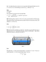
Operation of the Trackmate cleaning cassette The Trackmate system has engineered
quality cleaning into a single, easy-to-use cassette (Fig. 2-34). Other cleaning cassettes are
technically dependent on fabric tape or felt for cleaning. Tapes are ineffective and do not
reach where dirt collects, beyond the tape path. Felts touch only a narrow portion of the
record/play head, capstan, and pinchroller, missing the erase head, tape guides, and stud
posts, leaving them dirty. The Trackmate brushes form fit all these mechanical parts. The
32,000 absorbent, flexible, fibers seek and remove dirt from all of the surfaces and gaps
where it collects (Fig. 2-35). Static-control fibers inhibit the attraction of further dust.
These high-tech cotton buds have more than 100 times the active cleaning surface area of
some earlier products. They automatically clean deck parts from top to bottom, leaving a
dirt-free path for the recording tape to safely track around on. Figure 2-36 shows the spe-
cial cleaning fluid being applied the Trackmate fiber brushes.
AUDIOCASSETTE PROBLEMS, SOLUTIONS, AND CORRECTIONS
The following information includes cassette problems that you may have and tips on what
to do to solve these problems:
Portable cassette—no tape movement or sound Always check the batteries first for
any portable cassette problems. Replace if dead or weak. Some portable cassettes will
CASSETTE PLAYERS—OPERATION AND MAINTENANCE 79
FIGURE 2-34
The Trackmate cleaning cassette device.
80 RADIO/AUDIO/STEREO/SPEAKERS/MUSIC SYSTEMS AND CASSETTE PLAYER OPERATIONS
FIGURE 2-35
The Trackmate cleaning cassette has 32,000 absorbent, flexible
FIGURE 2-36
Cleaning fluid is being applied to the Trackmate fiber brushes.
cleaning fibers.
have a small leaf spring that makes contact when record, play, fast forward, and rewind are
switched into action. Check and clean these copper spring-type contacts with a cleaning
fluid, or pull a very fine piece of sandpaper between the closed contacts. If the batteries
and contacts are good, then the motor is probably defective.
Sluggish tape rewind You will find that rewind and fast forward run faster than the
play/record modes. In some older-model players in the rewind mode, the shifting idler
wheel is shifted when the rewind button is pushed against the turntable reel assembly as
shown in Fig. 2-37. Check for worn or slick, shinny surfaces on the idler or drive wheel
area. Clean well with alcohol. Note that the pinch roller does not rotate in either direction
for rewind or fast forward.
With a gear drive system, the idler is shifted against the gear of the supply spindle. Usu-
ally, you will find that the rewind speed is slower than the fast forward speed. In rewind,
the capstan gear rotates the large drive gear, which in turn rotates the shifter idler gear, and
the idler drives the gear on the bottom of the supply spindle.
No fast forward action With most surface drive tape systems, the idler wheel is flipped
over to rotate the take-up reel. The idler wheel is rotated by friction driving against a wheel
that is attached to the capstan/flywheel shaft. If the cassette player works normally in play
mode and slow in fast forward, then suspect slippage on the idler drive area. Note Fig. 2-38.
Clean all drive surfaces. When the fast forward is belt driven, clean the belts and drive
pulley. Should both play and fast forward operate slowly, clean the motor belt and fly-
wheel surfaces.
CASSETTE PLAYERS—OPERATION AND MAINTENANCE 81
Supply reel
Shift idler wheel
Take-up reel
FIGURE 2-37
The idler wheel will shift toward the supply reel in the
rewind mode.
In some model cassettes, the fast forward and rewind are driven from small plastic gears.
These small plastic teeth mesh when switched to fast forward. The capstan gear rotates a
larger idler wheel and drives another shifting idler gear wheel. Refer to Fig. 2-39. The idler
gear is shifted toward the take-up spindle, which engages two small gear wheels. At the
bottom of the take-up reel is a plastic gear wheel that rotates in fast forward and play.
82 RADIO/AUDIO/STEREO/SPEAKERS/MUSIC SYSTEMS AND CASSETTE PLAYER OPERATIONS
Take-up reel
Fast forward roller
Shifting idler
Supply reel
FIGURE 2-38
The idler wheel is shifted toward the fast forward roller.
It will then drive the take-up reel at a faster speed.
Flywheel
Drive belt
Motor
Gear for
take-up reel
Fast forward gear
Idler shift gear
Supply reel gear
FIGURE 2-39
The small plastic gears are shifted into different positions for
various cassette functions. In this drawing the idler gear is positioned to spin the
take-up spindle at a faster forward speed.
These gear-type assemblies generally will not operate slowly or slip while rotating.
Check for broken gear teeth or jammed gears when fast forward does not rotate. A miss-
ing C washer can let the small gears fall out of line, and this will disable the fast forward
and play modes.
Auto shutoff not working When the cassette is out of tape, increased tension on the tape
triggers a small ejection lever that mechanically releases the play/record assembly and
turns the drive or motor to off. In more expensive units, mechanical and electronic automatic
shutoff systems are utilized. In many units the ejection lever is referred to as a detection or
contact piece, as shown in Fig. 2-40.
The automatic stop-eject or detection piece has a plastic cover over a metal angle lever
that can be adjusted at the end where it triggers the play/record assembly and the automatic
stop. The ejection piece is mounted alongside the tape head. When the end of the tape has
been reached, the tape exerts pressure against the ejection piece and mechanically triggers
the play/record mechanism.
Check the adjustment of the auto stop mechanism when the tape will not shut the machine
off automatically. Check and see if the lever is bent out of line. The eject or detection piece
should ride against the tape at its end. Straighten up the lever or replace it to correct the
auto shutoff problem. You can carefully place a drop of oil at the bearing if the ejection
piece is binding or difficult to move.
Checking the belt drives There are various belt drive systems found to operate cassette
machines. A majority have a belt drive to the capstan assembly. The drive belt is very
small in the mini/microcassette players. The motor drive belt in some models is very short.
These drive belts are usually flat or square in shape.
In addition to the motor drive belt, another belt runs from the flywheel to the take-up reel. A
few models of the mini-cassette players have a fast forward drive belt. Because these belts are
very small and thin, they have a problem of stretching and will then cause slow speeds. Clean
each of these belts when you have a speed or “wow” problem with alcohol and a clean cloth.
After these belts are cleaned and you still have a speed problem, replace the motor drive belt.
CASSETTE PLAYERS—OPERATION AND MAINTENANCE 83
Record/play head
Tape
Detection piece
FIGURE 2-40
The detection piece is located close to the tape path to shut
down the unit when end of the tape is reached.
Cassette switch problem notes You will usually find many small switches used in
these personal cassette player/recorders. The sound-level equalizer (SLE) switch improves
recording in locations away from the source, such as auditoriums and conference rooms.
The pause and VAS are slide switches. Usually, the radio-tape switch is a slide switch.
When these switches do not work, or are erratic or intermittent, squirt a switch cleaning
spray down into the switch contact. Try not to get any of this cleaning fluid on the belts or
idler wheels.
The on/off switch that controls power to the motor and amplifier circuits could be a leaf
switch that is pressed together for record, play, rewind, or fast forward. These small switch
contacts could become dirty; if so, clean them with a switch cleaning fluid. Suspect a defec-
tive or dirty leaf switch when you have intermittent operation. These switches are usually
squeezed together with a metal lever that may need to be adjusted.
Unit will not load cassette cartridge Check inside the tape holder for any dirt or for-
eign material. Check to make sure the record safety lever will release. Check for any
cracked or broken holder. Also, the cassette may be cracked or broken. Try a new cassette
tape.
Inspect for proper door closing. Check to make sure the unit is in the play mode. The
mechanism may be misaligned and will not let the cassette load. Look for any small items
that may be inside the cassette holder that can prevent proper cassette loading.
Cassette blows fuses In the larger-model cassettes, suspect a blown fuse if the unit is
dead and nothing will light up. A good place to start is to look for a shorted silicon diode
rectifier in the power supply. Also, a shorted filter capacitor, IC, or output transistor could
be the culprit. Remove these components one at a time, and if the fuse does not blow, then
you have probably found the defective component.
The deluxe stereo cassette players with higher-power audio output may have four large
transistors. Usually, two are located for each audio output channel. You can check out
which channel is blowing the fuse by taking a low-ohm resistance measurement between
the collector of these transistors and ground. Now test each one while in circuit for leak-
age. Next, test them out of circuit for leakage. You may find one transistor shorted and the
other one open.
While the transistors are out of the circuit, check for burned or open bias resistors. Usu-
ally, when a power-output transistor is shorted, the bias resistor will open up. Also, when
the two transistors are out of the circuit, check the driver transistor. In some cases the dri-
ver transistor becomes leaky and this can damage the directly coupled power-output tran-
sistors. Most all power-output transistors can be replaced with universal types. Leaky
power-output ICs may also blow out the fuse.
Deck shuts down after a few seconds If you have a case where the tape deck keeps
shutting off after only a few seconds, suspect that the automatic shutoff circuits are not
working. In these units with automatic shutoff, a magnet is fastened to the end of a pulley
on the counter assembly. Some models have a magnetic switch behind the magnet or IC.
The magnet must keep rotating to keep the cassette player operating. When the magnet or
tape stops, the magnetic switch or IC will shut down the operation of the cassette unit.
Should the drive belt to the counter be broken, the cassette will start up and shut down im-
mediately. Check for a broken belt from the counter pulley. Note if the tape counter is rotat-
ing. If the belt is operating and the counter pulley is also, but the unit shuts down, suspect a
84 RADIO/AUDIO/STEREO/SPEAKERS/MUSIC SYSTEMS AND CASSETTE PLAYER OPERATIONS
defective switch or IC. An IC is used in some units while other models have a magnetic
switch. The magnetic switch and ICs are special components.
A smoking cassette unit Quickly pull the ac plug on any cassette or other electronic
equipment if it’s smoking. With an ohm meter check the primary winding of the power
transformer for an open condition. If it’s OK, then check the B+ supply voltage or make a
resistance measurement across the large filter capacitor. An ohm reading below 100 indi-
cates a short circuit.
If the transformer is overheating, check each silicon diode for a short. Also, a shorted or
high leakage of the output IC or transistor will cause the power transformer to overheat.
If the transformer has been overheating and the above checks are OK, then remove all
other secondary transformer connections. Now plug the AC cord of the cassette into the
wall unit and if the transformer still runs hot or makes a noise, then it must be replaced.
Refer to Fig. 2-41 for this power supply circuit.
Noise problems If you hear loud mechanical noises, shut the cassette down and check
it out. Should the noise be a crackling, fuzzy, or frying noise, then suspect an IC or tran-
sistor fault. Now check for noise in each speaker. If you hear frying noise in only one chan-
nel with the volume turned down, then the noise is being developed in that audio output
channel.
To isolate the faulty component, spray each transistor or IC with coolant and note if the
noise stops or becomes louder. You should spray each component several times before
moving onto another one. At times when the coolant hits the faulty component the noise
will quiet immediately.
If the coolant test does not indicate a problem, you can try shorting the base of transis-
tors or input of ICs to ground with an electrolytic capacitor. Start at the volume control and
CASSETTE PLAYERS—OPERATION AND MAINTENANCE 85
120 VAC
Volt/ohm meter
C
4
C
5
C
2
C
3
C
1
T1
Power
transformer
F
ilter cap
B+
Diode chip
FIGURE 2-41
Use a volt-ohm meter to check for proper voltage and any
shorted components. Replace transformer T1 if it runs hot after all connections
and loads are removed.
work to the output stages and speaker. When the noise goes low in volume or quiets, then
you have located the faulty stage. Testing may not reveal the defective component so it's
best to replace it. You may also find a defective bypass capacitor in the audio circuits that
can be causing a frying noise.
Rewind and fast forward problems Usually the more expensive cassette decks have
two motors. One motor is used for regular playback and the other for faster forward and
rewind speeds. Suspect a defective high-speed motor or circuit when the deck does not
rewind or go into the fast forward mode.
Check for proper voltage into the motor terminals. To do this connect your volt meter
across the motor leads and then push the fast forward button. If it still does not operate,
push the rewind button. If there still is no tape movement, then suspect a faulty motor if
voltage is OK across its terminals. Also, check the possibility that a diode or resistor may
be open in series with the motor leads if voltage is found at the terminals. Also, look for
broken belts if the rewind or fast forward is not performing properly.
Erratic tape speed In some cases erratic speed could be caused by a loose motor drive
belt, an oily belt, or a dry capstan bearing. For this speed problem clean the motor drive belt,
motor pulley, and capstan/flywheel.
Uneven tape speed can also be caused by a pinch or pressure roller that is not perfectly
round or is worn. Check the rubber pinch roller area for broken tape. In many cases when
the tape spills out and breaks, excess tape is wound around the pinch roller. The pressure
roller can be removed for cleaning and removal of tape that is wound around it. Before
replacing the pressure roller, put a drop of oil on its bearing. Do not get any oil on the rub-
ber parts. Make sure the roller will move freely.
Check to make sure the pressure roller spring has enough tension. The pressure roller
helps pull the tape, along with the capstan, across the tape heads and feeds it onto the take-up
reel table. Make sure the pinch roller runs smoothly and evenly. Replace the pinch roller if
it’s lopsided or has worn edges.
Poor recordings You can be sure that the erase head is not working if you hear several
recordings during playback. The erase head erases any previous recording before the tape
passes the record/play head(s). To check, place the unit in the record mode but do not have
any audio input. Operate the unit in the record mode for a few minutes. Now, rewind the
tape and put it into the play mode. All of the previous recordings should be removed.
Should the tape still have recordings on it, the erase circuits are not working. Clean the
erase head and any other heads with alcohol. Also, clean the record/play switch with a
spray switch cleaner. Now recheck again.
If the recordings are still on the tape after cleaning, check the erase head for an open
winding or broken lead wires to a head. Also check for a good ground connection to the
erase head. Check for a dc voltage to the erase head. Use a scope to check for the bias oscil-
lator waveform, as that is required for the erase head to function.
Fast forward problems (single-motor unit) The fast forward function in a single-motor
deck is done with mechanical idlers or gears to increase the speed. In some of these decks,
another winding runs at a faster rate of speed. When the player is placed in fast forward,
the normal running motor wire is out of the circuit and the fast forward winding is
switched into action.
86 RADIO/AUDIO/STEREO/SPEAKERS/MUSIC SYSTEMS AND CASSETTE PLAYER OPERATIONS
With normal-speed operation, the B+ voltage is fed to the main winding and through
a resistor and capacitor. In fast forward, the switch places the fast forward winding to the
B+ and removes the resistor and capacitor from the circuit. In these cassette systems, the
motor speed is changed by switching the windings at the motor instead of using a mechani-
cal scheme.
Following is a list of symptoms, causes, and solutions:
Symptom: Cassette tape will not move.
What to do: Clean and/or adjust the control switches.
Probable cause: Motor not running.
What to do: Replace motor.
Probable cause: Drive belt worn or broken.
What to do: Replace with new belt.
Symptom: Tape movement erratic or slow.
Probable cause: Motor bearing dry or drive belt worn.
What to do: Replace motor or drive belt.
Probable cause: Oil or grease on capstan.
What to do: Clean capstan with alcohol.
Probable cause: Pinch roller dirty or cassette defective.
What to do: Clean pinch roller and try a new cassette tape.
Symptom: Tape tears or jams.
Probable cause: Take-up reel torque is too high.
What to do: Adjust or clean turntable clutch assembly.
Probable cause: Bent tape guide or misaligned head.
What to do: Replace head or readjust.
Symptom: Tape will not wind properly.
Probable cause: Tape torque is too low.
What to do: Adjust clutch subassembly.
Probable cause: Clutch arm assembly worn.
What to do: Replace clutch arm assembly.
Probable cause: Pinch roller out of alignment with capstan.
What to do: Adjust pinch roller or replace it.
Probable cause: Belt loose or off clutch assembly.
What to do: Clean belt and/or replace it.
Probable cause: Take-up idler wheel is worn.
What to do: Replace idler wheel.
Symptom: Tape speed is too slow.
Probable cause: Voltage to motor is low.
What to do: Check power supply.
Probable cause: Drive belt is slipping.
What to do: Clean or replace drive belt.
Probable cause: Motor stalls.
What to do: Replace motor.
Probable cause: Pinch roller is dirty.
CASSETTE PLAYERS—OPERATION AND MAINTENANCE 87
What to do: Clean pinch roller with alcohol.
Probable cause: Oil or grease on capstan.
What to do: Clean capstan with alcohol.
Symptom: Wow and flutter during playback.
Probable cause: Cassette pad pressure is too high.
What to do: Replace with a new cassette.
Probable cause: Pinch roller is dirty or worn.
What to do: Clean or replace pinch roller.
Probable cause: Oil on capstan or other moving parts.
What to do: Clean all of these parts.
Probable cause: Capstan shaft is eccentric.
What to do: Replace flywheel.
Probable cause: Tape not following (tracking) in the proper path.
What to do: Check all components and realign the tape path.
Symptom: Fast forward is inoperative.
Probable cause: Fast forward torque is low. Clean or replace fast-forward clutch assem-
bly. Replace spring in fast-forward clutch if pressure is low.
Probable cause: Defective motor.
What to do: Replace motor.
Symptom: Tape will not rewind.
Probable cause: Idler arm damaged.
What to do: Replace idler arm.
Probable cause: Rewind torque is weak.
What to do: Clean fast-forward clutch, idler assembly, and drive reel surfaces from oil,
grease, or other impurities. Replace any rubber surfaces that are worn or uneven.
Probable cause: Brake assembly is still in contact with drive reels.
What to do: Adjust, repair, or replace the brake assembly.
Symptom: Rewind speed is slow.
Probable cause: Supply voltage is low or motor is defective.
What to do: Check power supply or install new motor.
Probable cause: Idler is slipping.
What to do: Replace or clean idler wheel.
Symptom: Tape climbs up capstan.
Probable cause: Shaft of pinch roller assembly is bent or loose.
What to do: Replace pinch roller assembly.
Symptom: No audio when playing a tape back.
Probable cause: Defective play/record head.
What to do: Replace or clean play/record head.
Probable cause: Defective power supply or playback amplifier circuits.
What to do: Check the power supply and recorder electronic playback circuits.
Probable cause: Defective cables or cable connections to the power amplifiers or speakers.
What to do: Check all connections and cables. Check power amplifiers for proper
operation.
88 RADIO/AUDIO/STEREO/SPEAKERS/MUSIC SYSTEMS AND CASSETTE PLAYER OPERATIONS
Symptom: No sound, only noise comes from the speakers.
Probable cause: Record/play head open.
What to do: Replace the play/record head.
Probable cause: Open or short circuit in cable to head or faulty plug connection.
What to do: Clean connections and cable or replace cable assembly.
Probable cause: Shielded wire between record/play head and circuitry is pinched, cut, or
shorted.
What to do: Replace this shielded wire or repair.
Symptom: Weak playback audio sound.
Probable cause: Dirty play/record head. Check and clean.
Probable cause: Defective amplifier components.
What to do: Check voltages and repair amplifier stages.
Probable cause: Cassette is defective.
What to do: Try a known-good cassette.
Symptom: Poor high-frequency audio response on playback.
Probable cause: Record/play head is dirty.
What to do: Clean the head.
Probable cause: Azimuth adjustment is wrong.
What to do: Check and correct azimuth adjustment if it is wrong.
Probable cause: Record/play head is magnetized.
What to do: Demagnetize the head.
Symptom: The volume varies on tape playback.
Probable cause: Improper pressure of record/play head against the tape.
What to do: Adjust for proper head penetration.
Probable cause: The tape is not following the proper path.
What to do: Check and adjust mechanical components in the tape path.
Symptom: Audio is distorted during tape playback.
Probable cause: Defective components such, as transistors and ICs, in the playback
amplifiers.
What to do: Repair audio amplifiers.
Probable cause: Defective speakers or connections.
What to do: Check for poor speaker lead connections or rubbing voice coils and warped
speaker cones. Replace speakers if defective.
Probable cause: Record/play head is dirty.
What to do: Clean the head and adjust if necessary.
Symptom: Tape not being recorded in Record mode.
Probable cause: Defective play/record head.
What to do: Replace defective head.
Probable cause: Defective bias oscillator circuit.
What to do: Repair bias oscillator circuit. A typical bias oscillator circuit is shown in
Fig. 2-42.
CASSETTE PLAYERS—OPERATION AND MAINTENANCE 89
Symptom: No recording be made with microphones.
Probable cause: Defective microphone or microphone plug in jacks.
What to do: Replace microphone or repair the plug-in microphone jacks.
Symptom: Tape cannot be erased.
Probable cause: Defective erase head, dirty erase head, or bias oscillator not working.
What to do: Replace or clean erase head. Repair bias oscillator circuit.
90 RADIO/AUDIO/STEREO/SPEAKERS/MUSIC SYSTEMS AND CASSETTE PLAYER OPERATIONS
Bias
osc. IC
B+
voltage
B+
voltage
To bias switch circuit
Left record
head
Right record
head
Erase head
FIGURE 2-42
A simplified bias oscillator circuit is shown. The bias
oscillator signal is fed to the left and right recording heads and to the erase
head.
3
AUDIO/VIDEO AND
CD PLAYER
OPERATIONS
91
CONTENTS AT A GLANCE
How CD and Laserdisc Players Work
Skip, search, and scan operation
How the laserdisc is made
DVD Discs
DVD technology
Laser light and laser diode
information
CD player sections
The electronics PC board
The disc motor
The spindle platform table
The sled mechanism
The pickup motor
The disc clamper
The optical pickup unit
CD Player Problems and solutions
Some CD player commands will not
function
Dead CD player
Drawer will not open or close
Unpredictable drawer operation
Drawer will not close properly
Various intermittent operation
modes
Problems develop after unit heats
up
Player audio problems
A review of common CD player
problems
Checking and Cleaning the Laser Player
CD player will not operate (start-up)
The CD sequence start-up routine
Notes on CD readout failures
CD skipping problems
Noise problem
Optical pickup sled comments
How CD and Laserdisc Players Work
To explain CD player operation, this chapter uses a Zenith LDP510 multi laserdisc player.
This laserdisc player produces very good quality video and audio.
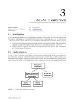
Figure 3-1 shows the cartridge for a Pioneer audio CD player that uses a six-disc plug-in
CD holder. In Fig 3-2, you can see how these CDs swing out to load and also play them. Fully
loaded, these cartridges will give you six hours of uninterrupted music in your home or auto.
The Zenith laserdisc and CD player can play back five different kinds of discs:
■ 12-inch laserdiscs (LD) These can contain up to 120 minutes (60 minutes per side) of
high-quality video and digital or analog audio.
■ 8-inch laser discs (LD single) Plays back up to 40 minutes (20 minutes per side) of
high-quality video and digital or analog audio.
■ 5-inch compact disc video (CDV) This plays up to 5 minutes of high-quality video and
up to 20 minutes of digital audio.
■ 3-inch compact disc (CD single) This plays up to 20 minutes of digital audio.
92 AUDIO/VIDEO AND CD PLAYER OPERATIONS
FIGURE 3-1
A six-CD
cartridge that slides into
a Pioneer home or auto
CD player device.
This Zenith multidisc player is a remarkably versatile player unit for both video and
audio playback modes. Unlike video and audio tape players, these players can quickly find
a specific point on the recorded CD.
SKIP, SEARCH, AND SCAN OPERATION
Now look at how the disc players perform these search and scan operations.
Chapter/program skip Most laserdiscs are divided into segments or chapters, and com-
pact discs are divided into programs. Each program on an audio CD is usually an individ-
ual song. With either a laser or compact disc loaded in the CD player machine, pressing the
Skip button, forward or reverse, will cause it to skip almost instantly to the beginning of
the next or previous chapter or program.
Chapter/program search mode Laserdiscs and CDs with individual chapter or program
numbers and descriptions written on the jacket label make it even easier to access specific
segments directly. Simply press the Chapter/program key on the remote control and then
the desired number of the chapter or program to be played back.
Disc scan mode Both laserdiscs and CDs can be scanned by the Zenith laserdisc player
to access a section within a chapter or program. Laserdiscs recorded in CAV (standard
play) will show high-speed playback of the video on the TV screen. Compact discs, too, will
deliver high-speed audio playback when scanning.
HOW CD AND LASERDISC PLAYERS WORK 93
FIGURE 3-2
Another view of the Pioneer six-CD cartridge, showing how the
discs swing out for replacement. This cartridge, when fully loaded, can provide
approximately 6 hours of music.
The laserdisc players all use the same operating principles as CDs and CVDs. This
Zenith player is capable of playing these discs in addition to laserdiscs.
The recording of the master disc is accomplished (as shown in the description blocks of
Fig. 3-3). The video is FM modulated on a 8.5-MHz carrier frequency. Audio signals are
94 AUDIO/VIDEO AND CD PLAYER OPERATIONS
FM modulator: The video signal is
FM modulated and changes into
video FM waves.
FM modulator: The audio signals (2 channels)
are independently FM modulated, and change
into audio FM waves.
Composite circuit: FM video signals
and FM audio signals are combined
to create composite signals.
Limiter: The composite signals
amplitudes are limited for driving
the modulator.
Optical modulator: On the basis of
the limiter signals, the laser beam is
turned on/off and irradiates the
master disk.
Laser
Video signals
Audio signals (2 channels)
Master disk
Motor for spinning the disk
FIGURE 3-3
A block diagram of how a laser master disc is
produced. (Zenith Corp.)
also FM (frequency modulated) on two carrier frequencies at 2.3 MHz and 2.8 MHz. The
video and audio signals are combined to create a composite FM signal. This is passed
through a limiter before going onto the modulator. In the limiter, the FM signal wave is
formed into square waves that are coupled to the modulator to turn the laser beam on and
off to create pits in the disc surface.
The master disc is composed of a photoresist, that is exposed by the laser beam, to cre-
ate pits, in accordance with the video and audio information from the FM carrier wave.
The master disc is then used to produce a completed laser vision disc.
The frequency spectrum of a recorded signal is shown in Fig. 3-4. The video frequency
spectrum is from 4 to 14 MHz, thus giving it a very wide bandwidth. The chrome signal is
comprised of a low frequency and is then frequency converted to produce sidebands as
indicated. In this spectrum is a vacant space from 0 to 2 MHz, allowing for digital audio
signal recording.
HOW THE LASERDISC IS MADE
Precision recording and playback of the CD in the very small micron scale is possible because
laser beams are used for cutting. The rows of audio and video signals (called pits, recorded
as bumps on the disc surface) are actually tracks impressed on one side of the CD disc.
Each of these tracks contains one video frame.
One picture after another is picked up at the rate of 30 frames per second to produce a full
TV picture during playback.
Disc construction information Of the six types of CD discs, the 5-inch size is the most
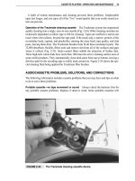
popular today. Refer to Fig. 3-10 for more details on these disc types. The 12-inch disc con-
sists of two one-sided discs (300 mm in size) that are bonded together and are 1.2 mm thick.
Program recordings begin at the 110-mm diameter point and end wherever the program ends,
HOW CD AND LASERDISC PLAYERS WORK 95
010
246
8
12
14
-60
-40
-20
0
Digital audio
Frequency (MHz)
R
ecording
level (db)
Audio FM carrier
Video FM carrier
Upper side chroma
sideband wave
Lower side chroma
sideband wave
7.6 MHz
9.3 MHz
FIGURE 3-4
The frequency spectrum chart of the laser CD beam. (Zenith Corp.)
up to a maximum diameter point of 290 mm. The shape, dimensions and cross-section view
of the CD is illustrated in Fig. 3-5. Disc playback systems are classed as either standard
(CAV) discs, which play for 30 minutes on one side, or long-playing (CLV) discs, which
play for 60 minutes on one side. In either case, playback begins on the inner circumference
and ends at the outer circumference.
96 AUDIO/VIDEO AND CD PLAYER OPERATIONS
(1)Shape and dimension
(2)Cross-sectional dimension
Lead out area: 1 mm
Aluminum reflective film
Plastic protective film
Rubber adhesive layer
PMMA resin
Label
Center hole
Lead in area
Program area
Lead out area
35
1.25
scale: mm
2.6
2.7
Program
area
Lead
in area:
900 track,
1.5 mm
Label
2.6 mm
maximum 290
mm
110
mm
35
mm
93
mm
300
mm
93
53.5
56
maximum
145(96)
150(100)
FIGURE 3-5
The shape and dimensions of a cross-sectional drawing of a laser
disc. (Zenith Corp.)
A lead in about 1.5 mm wide is placed at the inner circumference, which is before the
program starting point. The lead in serves as the intro for the program and contains infor-
mation, such as the trademark of the company that made the disc.
A lead out at least 1 mm wide is located at the outer circumference, which is after the
program ending point. It is used to display information, such as the end mark. The installed
CD discs rotate clockwise when viewed from the top of the machine.
Standard discs rotate at a constant 1800 RPM (rotations per minute), but because long-
playing discs are recorded at a constant linear velocity of 11 m/s, the number of rotations
vary with pickup location from the inner circumference (1800 rotations) to the outer cir-
cumference (600 rotations). The center hole of the disc is 35 mm in diameter to provide
stable support and suppress warping—even when the disc rotates at such high speeds.
How the disc is constructed A resin protective-film coating is applied above an alu-
minum reflective film deposited on the pit transfer surface of the 1.2-mm thick PMMA
base (transparent acrylic resin disc).
Because the protective films are bonded together, the pits of recorded information on
finished discs are fully protected by embedding them at least 1.2 mm from the disc surface.
Refer to Fig. 3-6 for the construction of the disc’s internal structure.
This structure protects against scratches and dust on the signal pickup surface, and pre-
vents scratches and fingerprints from deteriorating the audio or video quality during play-
back. This is also because the laser beam is precisely focused on the signal (pit) and the
disk surface is outside the focal point. Discs have a very long operating life because you
can wipe them clean with a soft cloth when they get very dirty. Handling and storage of the
CD discs are very easy and convenient.
Signal (pit) detection scheme Now see how the disc signal (pit) and signal pickup is
accomplished. The pickup of a laserdisc player extracts signals impressed on the disc for
amplification and playback, and generates an output that can be used as audio and video
signals for TV picture reproduction.
HOW CD AND LASERDISC PLAYERS WORK 97
Pit
Side 1
Side 2
Disc surface
Laser beam
PMMA resin
Reflective film
Protective film
Adhesive layer
2.5 mm
1.5 m
.5 m
.1.67 m
.75 mm
FIGURE 3-6
A drawing
of the internal structure of
a laser disc.
(Zenith Corp.)
Each laserdisc signal is recorded as bump-like pits in varying sizes. The signal record-
ing method is exactly like that for CDs (compact discs), so the method for extracting sig-
nals is also the same.
A semiconductor laser emits a pin point of light on a laserdisc. Only light that strikes
a pit and is reflected is picked up and converted to an electrical signal. This operation is
depicted in Fig. 3-7. The slight distance maintained between the pickup and the signal sur-
face prevents damage to the pickup and disc. These are the advantages of the noncontact-type
laserdiscs.
Optical pickup and detection via the pit signal Almost all light emitted from the semi-
conductor laser is reflected at locations without the pits. A reflected light differential
(power) is generated at the pit locations because only a portion of the light is reflected.
Because the length of each pit differs according to the impressed information, the reflected
light differential (power) based on the varying length is converted to an electrical signal by
the photodiode. Eventually, it becomes the audio and video signals, as shown in Fig. 3-8.
Light shone on the disc and reflected back just as it would return to its place of origin
during the process of signal extraction, so an extraction method that can identify the light is
required. For this job, a half mirror is used because it reflects 50% and passes the other 50%.
Besides the route just described, the light also passes through the grating, collimator
lens, and objective lens. Each of these items are designed to control the direction in which
the light advances and then to assign the correct signal to the pit.
The laserdisc pits The size of a disc pit that represents a recorded signal is extremely
small. An enlarged view of these pits are shown in Fig. 3-9.
A standard CD contains approximately 12 to 15 billion pits on one side. To get some per-
spective on this number, you can think of it as roughly equivalent to the number of brain
cells in an adult person. The large 12-inch disc would contain much more information.
These tiny pits lined up on a single circuit of the disc is called a track. One track contains
information for a single picture or screen full on a TV. Two fields, like that on a TV, are
formed from 30-frame screens every second.
98 AUDIO/VIDEO AND CD PLAYER OPERATIONS
Objective lens
Film-deposited
aluminum
PMMA resin (transparent)
Plastic protective film
1.67m
FIGURE 3-7
A drawing
of how the laser signal op-
erates and picks up data
from the CD disc.
(Zenith Corp.)
Movies are 24 frames and one laserdisc track equals one frame. Consequently, one side
of a laserdisc records 54,000 tracks. Because 30 tracks form a one-second image, one side of
a disc records 30 minutes of video.
Various types of CDs The types of discs that can be played back on laser players are
shown in Fig. 3-10. Nearly all discs are LD, CD, or CDV compatible. Let’s now look at
the specifications of these various laserdiscs.
Standard (CAV) discs These standard discs have a constant angular velocity. A disc spins
with a constant rotational speed of 1800 RPM. Playback time on one side of a 12 inch
disc is 30 minutes, recording a maximum of 54,000 frames of picture information. As the
HOW CD AND LASERDISC PLAYERS WORK 99
(a) Laser beam light reflection when there
is no pit on the signal surface (almost all the
light is reflected)
(b) Laser beam light reflected by a pit
Pit on a track
Photodiode output (amount of reflected light)
Time
FIGURE 3-8
Signal extraction from the disc by the optical pickup device. (Zenith Corp.)
0.4m
1.67m
FIGURE 3-9
A magnified view of the pit found on a CD
disc. (Zenith Corp.)
disc spins once, it turns each picture frame, which are each provided with frame numbers
from l to 54,000.
Long play (CLV) These discs have a constant linear velocity. The rotational speed
changes accordingly, when the signal in the inner circumference is being read, it spins at
1800 rpm. When the signal in the outer circumference is being read, it spins at 600 rpm.
The playback time for one side of a 12-inch disc is 60 minutes. The playback elapsed time
is recorded on the disc from the beginning.
Compact disc with video (CDV) Pictures associated with digital sound are recorded on
the outer tracks (video part) five minutes long. Digital audio on the inner tracks (audio)
20 minutes: A normal playback begins at the video part through to the audio part.
The main component of this CD equipment is the mechanical operating portion. This
part of the CD player is broadly divided into the pickup carriage portion and the mechan-
ical subchassis section that handles the loading and motor elevation operations. This CD
player section is shown in Fig. 3-11.
How the pickup carriage functions
■
The pickup carriage, which features all tilt mechanisms, including a tilt sensor and tilt
motor, is driven in the feed direction along the feed rack. A drawing of this pickup car-
riage unit is shown in Fig. 3-12.
■ This pickup carriage is equipped with a mechanism to adjust the tilt sensor mounting
angle (screw) so that the sensor is constantly vertical in the radial direction with respect
100 AUDIO/VIDEO AND CD PLAYER OPERATIONS
Disc
CD
CDV
LD
Disc
size
20 minutes
(one side only)
LD singleCD single
74 minutes
(one side only)
25 minutes
(one side only)
Audio only:
digital audio
Video & digital / analog audio
Maximum
recording
time
Recorded
contents
Indication
symbol
A: Video&Digital audio
(5 min.)
B: Digital audio (20 min.)
CAV: 14 mins.
3-inch
CAV: 28 mins.
CLV: 40 mins.
CAV: 60 mins.
CLV: 120 mins.
CLV: 20 mins.
(one side only)
5-inch 5-inch
8-inch
8-inch
12-inch
A
B
Types of discs
The following types of discs can be played back on laser players because nearly all discs are LD, CD, or CDV
compatible
FIGURE 3-10
The various types and sizes of laser discs.
to the disc position. The tilt cam gear, which controls tilt, is equipped with an overtilt
mechanism to lower the position of the pickup when tray loading, and a limiter mecha-
nism to prevent the tilt cam gear from over rotating.
■ The pickup base to which the pickup is attached is adjusted in the normal direction by a
screw to maintain positional accuracy of the pickup in the normal adjustment direction.
How the mechanical subchassis works
■
The loading mechanism, spindle motor elevation mechanism that clamps the disc, and
the feed mechanism for the pickup carriage are located on the same chassis. All of these
operations are handled by a single loading motor.
HOW CD AND LASERDISC PLAYERS WORK 101
FIGURE 3-11
A laser disc drawer and its inside component view. (Zenith Corp.)
FIGURE 3-12
The tilt
sensor unit. (Zenith Corp.)
■ The loading mechanism uses an auto loading system so that a light push on the tray or
a press of the Open/close button triggers the loading motor to pull in the drawer. On
some PCs, the CD drawer is pulled in (loaded) as the program is being run.
■ The clamp mechanism raises the spindle motor to clamp a disc between the turntable
and the clamper mounted on the subchassis.
Protection, setting mode, playback, and disc ejection of each disc is performed by each
mechanical sequence on the subchassis that has just been described.
Mechanical tray operations Refer to Fig. 3-13. The tray has a guide groove on the right
side to engage the resin guide on the subchassis, as well as a drive transmission rack for
horizontal movement that engages the slide on the right bottom surfaces and drive gears on
the left bottom surfaces.
102 AUDIO/VIDEO AND CD PLAYER OPERATIONS
FIGURE 3-13
Component layout and parts location inside the laser player
drawer assembly. (Zenith Corp.)
A protrusion at the rear of the tray serves as a stopper. When the tray is finished unload-
ing, the stopper contacts the protrusion on the subchassis to prevent the tray from moving
too far forward.
The end of slide tray unloading operations is detected when the protrusion at the left rear
of the tray presses the limiter switch mounted on the subchassis side. In other words, the
loading motor is off when the tray is unloading, but a slight press on the tray breaks con-
tact between the protrusion on the tray and limiter switch. This causes the loading motor
to turn on, and the tray is automatically pulled into the player. Normal tray operation can
be performed by the player operating buttons.
The disc loading operations Refer to Fig. 3-14 for how the disc loading is accomplished.
The loading mechanism is made up of the following items:
■ Tray.
■ Slide plate assembly.
HOW CD AND LASERDISC PLAYERS WORK 103
FIGURE 3-14
Location of the bracket motor and Geneva gear assembly
located in the disk drawer. (Zenith Corp.)