Calculations for machine design ~ team tolly
Bạn đang xem bản rút gọn của tài liệu. Xem và tải ngay bản đầy đủ của tài liệu tại đây (3.31 MB, 465 trang )
P1: Shibu
Brown.cls Brown˙fm January 6, 2005 10:41
ii
MARKS’
CALCULATIONS FOR
MACHINE DESIGN
P1: Shibu
Brown.cls Brown˙fm January 6, 2005 10:41
This page intentionally left blank.
P1: Shibu
Brown.cls Brown˙fm January 6, 2005 10:41
MARKS’
CALCULATIONS FOR
MACHINE DESIGN
Thomas H. Brown, Jr., Ph.D., P.E.
Faculty Associate
Institute for Transportation Research and Education
NC State University
Raleigh, North Carolina
McGRAW-HILL
New York Chicago San Francisco Lisbon London Madrid
Mexico City Milan New Delhi San Juan Seoul
Singapore Sydney Toronto
iii
P1: Shibu
Brown.cls Brown˙fm January 6, 2005 10:41
iv
Copyright © 2005 by The McGraw-Hill Companies, Inc. All rights reserved. Manufactured in
the United States of America. Except as permitted under the United States Copyright Act of
1976, no part of this publication may be reproduced or distributed in any form or by any
means, or stored in a database or retrieval system, without the prior written permission of the
publisher.
0-07-146691-6
The material in this eBook also appears in the print version of this title: 0-07-143689-8.
All trademarks are trademarks of their respective owners. Rather than put a trademark symbol
after every occurrence of a trademarked name, we use names in an editorial fashion only, and
to the benefit of the trademark owner, with no intention of infringement of the trademark.
Where such designations appear in this book, they have been printed with initial caps.
McGraw-Hill eBooks are available at special quantity discounts to use as premiums and sales
promotions, or for use in corporate training programs. For more information, please contact
George Hoare, Special Sales, at or (212) 904-4069.
TERMS OF USE
This is a copyrighted work and The McGraw-Hill Companies, Inc. (“McGraw-Hill”) and its
licensors reserve all rights in and to the work. Use of this work is subject to these terms.
Except as permitted under the Copyright Act of 1976 and the right to store and retrieve one
copy of the work, you may not decompile, disassemble, reverse engineer, reproduce, modify,
create derivative works based upon, transmit, distribute, disseminate, sell, publish or
sublicense the work or any part of it without McGraw-Hill’s prior consent. You may use the
work for your own noncommercial and personal use; any other use of the work is strictly
prohibited. Your right to use the work may be terminated if you fail to comply with these
terms. THE WORK IS PROVIDED “AS IS.” McGRAW-HILL AND ITS LICENSORS
MAKE NO GUARANTEES OR WARRANTIES AS TO THE ACCURACY, ADEQUACY
OR COMPLETENESS OF OR RESULTS TO BE OBTAINED FROM USING THE WORK,
INCLUDING ANY INFORMATION THAT CAN BE ACCESSED THROUGH THE
WORK VIA HYPERLINK OR OTHERWISE, AND EXPRESSLY DISCLAIM ANY
WARRANTY, EXPRESS OR IMPLIED, INCLUDING BUT NOT LIMITED TO IMPLIED
WARRANTIES OF MERCHANTABILITY OR FITNESS FOR A PARTICULAR
PURPOSE. McGraw-Hill and its licensors do not warrant or guarantee that the functions
contained in the work will meet your requirements or that its operation will be uninterrupted
or error free. Neither McGraw-Hill nor its licensors shall be liable to you or anyone else for
any inaccuracy, error or omission, regardless of cause, in the work or for any damages
resulting therefrom. McGraw-Hill has no responsibility for the content of any information
accessed through the work. Under no circumstances shall McGraw-Hill and/or its licensors be
liable for any indirect, incidental, special, punitive, consequential or similar damages that
result from the use of or inability to use the work, even if any of them has been advised of the
possibility of such damages. This limitation of liability shall apply to any claim or cause
whatsoever whether such claim or cause arises in contract, tort or otherwise.
DOI: 10.1036/0071466916
P1: Shibu
Brown.cls Brown˙fm January 6, 2005 10:41
ii
Want to learn more?
We hope you enjoy this
McGraw-Hill eBook! If
you’d like more information about this book,
its author, or related books and websites,
please
click here.
P1: Shibu
Brown.cls Brown˙fm January 6, 2005 10:41
To Miriam and Paulie
v
P1: Shibu
Brown.cls Brown˙fm January 6, 2005 10:41
vi
This page intentionally left blank.
P1: Shibu
Brown.cls Brown˙fm January 6, 2005 10:41
CONTENTS
Foreword xi
Preface xiii
Acknowledgments xv
Part 1 Strength of Machines
Chapter 1. Fundamental Loadings 3
1.1. Introduction / 3
1.2. Axial Loading
/ 4
1.3. Direct Shear
/ 11
1.4. Torsion
/ 16
1.5. Bending
/ 24
Chapter 2. Beams: Reactions, Shear Force and Bending Moment
Distributions, and Deflections
33
2.1. Introduction / 33
2.2. Simply-Supported Beams
/
35
2.2.1. Concentrated Force at Midpoint / 36
2.2.2. Concentrated Force at Intermediate Point / 41
2.2.3. Concentrated Couple / 48
2.2.4. Uniform Load / 55
2.2.5. Triangular Load / 60
2.2.6. Twin Concentrated Forces / 67
2.2.7. Single Overhang: Concentrated Force at Free End / 73
2.2.8. Single Overhang: Uniform Load / 79
2.2.9. Double Overhang: Concentrated Forces at Free Ends / 86
2.2.10. Double Overhang: Uniform Load / 92
2.3. Cantilevered Beams / 97
2.3.1. Concentrated Force at Free End / 98
2.3.2. Concentrated Force at Intermediate Point / 104
2.3.3. Concentrated Couple / 110
2.3.4. Uniform Load / 115
2.3.5. Triangular Load / 120
Chapter 3. Advanced Loadings 127
3.1. Introduction / 127
3.2. Pressure Loadings / 127
vii
For more information about this title, click here
P1: Shibu
Brown.cls Brown˙fm January 6, 2005 10:41
viii CONTENTS
3.2.1. Thin-Walled Vessels / 128
3.2.2. Thick-Walled Cylinders / 130
3.2.3. Press or Shrink Fits / 134
3.3. Contact Loading / 139
3.3.1. Spheres in Contact / 139
3.3.2. Cylinders in Contact / 143
3.4. Rotational Loading / 147
Chapter 4. Combined Loadings 153
4.1. Introduction / 153
4.2. Axial and Torsion / 156
4.3. Axial and Bending / 159
4.4. Axial and Thermal / 164
4.5. Torsion and Bending / 167
4.6. Axial and Pressure / 172
4.7. Torsion and Pressure / 175
4.8. Bending and Pressure / 184
Chapter 5. Principal Stresses and Mohr’s Circle 189
5.1. Introduction / 189
5.2. Principal Stresses / 190
5.3. Mohr’s Circle / 205
Chapter 6. Static Design and Column Buckling 233
6.1. Static Design / 233
6.1.1. Static Design for Ductile Materials / 234
6.1.2. Static Design for Brittle Materials / 246
6.1.3. Stress-Concentration Factors / 258
6.2. Column Buckling / 260
6.2.1. Euler Formula / 261
6.2.2. Parabolic Formula / 263
6.2.3. Secant Formula / 266
6.2.4. Short Columns / 270
Chapter 7. Fatigue and Dynamic Design 273
7.1. Introduction / 273
7.2. Reversed Loading / 274
7.3. Marin Equation / 279
7.4. Fluctuating Loading / 285
7.5. Combined Loading / 311
Part 2 Application to Machines
Chapter 8. Machine Assembly 321
8.1. Introduction / 321
8.2. Bolted Connections / 321
P1: Shibu
Brown.cls Brown˙fm January 6, 2005 10:41
CONTENTS ix
8.2.1. The Fastener Assembly / 321
8.2.2. The Members / 326
8.2.3. Bolt Strength and Preload / 331
8.2.4. The External Load / 332
8.2.5. Static Loading / 335
8.2.6. Fatigue Loading / 337
8.3. Welded Connections / 348
8.3.1. Axial and Transverse Loading / 348
8.3.2. Torsional Loading / 352
8.3.3. Bending Loading / 356
8.3.4. Fillet Welds Treated as Lines / 360
8.3.5. Fatigue Loading / 365
Chapter 9. Machine Energy 367
9.1. Introduction / 367
9.2. Helical Springs / 367
9.2.1. Loads, Stresses, and Deflection / 367
9.2.2. Spring Rate / 371
9.2.3. Work and Energy / 375
9.2.4. Series and Parallel Arrangements / 377
9.2.5. Extension Springs / 379
9.2.6. Compression Springs / 380
9.2.7. Critical Frequency / 383
9.2.8. Fatigue Loading / 385
9.3. Flywheels / 388
9.3.1. Inertial Energy of a Flywheel / 388
9.3.2. Internal Combustion Engine Flywheels / 392
9.3.3. Punch Press Flywheels / 395
9.3.4. Composite Flywheels / 401
Chapter 10. Machine Motion
409
10.1. Introduction / 409
10.2. Linkages / 410
10.2.1. Classic Designs / 410
10.2.2. Relative Motion / 412
10.2.3. Cyclic Motion / 421
10.3. Gear Trains / 424
10.3.1. Spur Gears / 425
10.3.2. Planetary Gears / 428
10.4. Wheels and Pulleys / 431
10.4.1. Rolling Wheels / 432
10.4.2. Pulley Systems / 435
Bibliography
439
Index 441
P1: Shibu
Brown.cls Brown˙fm January 6, 2005 10:41
x
This page intentionally left blank.
P1: Shibu
Brown.cls Brown˙fm January 6, 2005 10:41
FOREWORD
Once the design and components of a machine have been selected there is an important
engineering analysis process the machine designer should perform to verify the integrity of
the design. That is what this book is about.
The purpose of Marks’ Calculations for Machine Design is to uncover the mystery
behind the principles, and particularly the formulas, used in machine design. All too often
a formula found in the best of references is presented without the necessary background
for the designer to understand how it was developed. This can be frustrating because of
a lack of clarity as to what assumptions have been made in the formula’s development.
Typically, few if any examples are presented to illustrate the application of the formula with
appropriate units. While these references are invaluable this companion book presents the
application.
In Marks’ Calculations for Machine Design the necessary background for every ma-
chine design formula presented is provided. The mathematical details of the development
of a particular design formula have been provided only if the development enlightens and
illuminates the fundamental principles for the machine designer. If the details of the devel-
opment are only a mathematical exercise, they have been omitted. For example, in Chapter 9
the steps involved in the development of the design formulas for helical springs are pre-
sented in great detail since valuable insight is obtained about the true nature of the loading
on such springs and because algebra is the only mathematics needed in the steps. On the
other hand, in Chapter 3 the formulas for the tangential and radial stresses in a high-speed
rotating thin disk are presented without their mathematical development since they derive
from the simultaneous integration of two differential equations and the application of ap-
propriate boundary conditions. No formula is presented unless it is used in one or more of
the numerous examples provided or used in the development of another design formula.
Why has this approach been taken? Because a formula that remains a mystery is a
formula unused, and a formula unused is an opportunity missed—forever.
It is hoped that Marks’ Calculations for Machine Design will provide a level of comfort
and confidence in the principles and formulas of machine design that ultimately produces
a successful and safe design, and a proud designer.
T
HOMAS H. BROWN,JR., PH.D., P.E.
xi
Copyright © 2005 by The McGraw-Hill Companies, Inc. Click here for terms of use.
P1: Shibu
Brown.cls Brown˙fm January 6, 2005 10:41
xii
This page intentionally left blank.
P1: Shibu
Brown.cls Brown˙fm January 6, 2005 10:41
PREFACE
As the title of this book implies, Marks’ Calculations for Machine Design was written
to be a companion to Marks’ Standard Handbook for Mechanical Engineers, providing
detailed calculations to the important problems in machine design. For each of the over
175 examples presented, complete solutions are provided, including appropriate figures and
diagrams, all algebra and arithmetic steps, and using both the U.S. Customary and SI/Metric
systems of units. It is hoped that Marks’ Calculations for Machine Design will provide an
enthusiastic beginning for those just starting out in mechanical engineering, as well as
provide a comprehensive resource for those currently involved in machine design projects.
Marks’ Calculations for Machine Design is divided into two main parts: Part 1, Strength
of Machines, and Part 2, Application to Machines. Part 1 contains seven chapters on the
foundational principles and equations of machine design, from basic to advanced, while
Part 2 contains three chapters on the most common machine elements based on these
principles and equations.
Beginning Part 1, Chapter 1, Fundamental Loadings, contains the four foundational
loadings: axial, direct shear, torsion, andbending.Formulas for stress and strain, both normal
and shear, along with appropriate examples are presented for each of these loadings. Thermal
stress and strain are also covered. Stress-strain diagrams are provided for both ductile and
brittle materials, and the three engineering properties, (E), (G), and (ν), are discussed.
Chapter 2, Beams, provides the support reactions, shear and bending moment diagrams,
and deflection equations for fifteen different beam configurations. There are ten simply-
supported beam configurations, from end supported, single overhanging, and double over-
hanging. There are five cantilevered beam configurations. Loadings include concentrated
forces and couples, as well as uniform and triangular shaped distributed loadings. Almost
45% of the total number of examples and over 30% of the illustrations are in this single
chapter. Nowhere is there a more comprehensive presentation of solved beam examples.
Chapter 3, Advanced Loadings, covers three such loadings: pressure loadings, to include
thin- and thick-walled vessels and press/shrink fits; contact loading, to include spherical
and cylindrical geometries; and high-speed rotational loading.
Chapter 4, Combined Loadings, brings the basic and advanced loadings covered in
Chapters 1, 2, and 3 together in a discussion of how loadings can be combined. Seven
different combinations are presented, along with the concept of a plane stress element.
Chapter 5, Principal Stresses and Mohr’s Circle, takes the plane stress elements devel-
oped in Chapter 4 and presents the transformation equations for determining the principal
stresses, both normal and shear, and the associated rotated stress elements. Mohr’s circle,
the graphical representation of these transformation equations, is also presented. The Mohr’s
circle examples provided include multiple diagrams in the solution process, a half dozen
on average, so that the reader does not get lost, as typically happens with the more complex
single solution diagrams of most other references.
Chapter 6, Static Design and Column Buckling, includes two major topics: design
under static conditions and the buckling of columns. The section on static design
covers both ductile and brittle materials, and a discussion on stress concentration fac-
tors for brittle materials with notch sensitivity. In the discussion on ductile materials, the
xiii
Copyright © 2005 by The McGraw-Hill Companies, Inc. Click here for terms of use.
P1: Shibu
Brown.cls Brown˙fm January 6, 2005 10:41
xiv PREFACE
maximum-normal-stress theory, the maximum-shear-stress theory, andthe distortion-energy
theory are presented with examples. Similarly, for brittle materials, the maximum-normal-
stress theory, the Coulomb-Mohr theory, and the modified Coulomb-Mohr theory are pre-
sented with examples. The discussion on stress concentration factors provides how to use the
stress-concentration factors found in Marks’ Standard Handbook for Mechanical Engineers
and other references. In the discussion on column buckling, the Euler formula is presented
for long slender columns, the parabolic formula for intermediate length columns, the secant
formula for eccentric loading, as well as a discussion on how to deal with short columns.
Chapter 7, Fatigue and Dynamic Design, contains information on how to design for
dynamic conditions, or fatigue. Fatigue associated with reversed loading, fluctuating load-
ing, and combined loading is discussed with numerous examples. The Marin equation is
provided with examples on the influence of its many modifying factors that contribute to
establishing an endurance limit, which in turn is used to decide whether a design is safe.
Extensive use of the Goodman diagram as a graphical approach to determine the safety of
a design is presented with appropriate examples.
Beginning Part 2, Chapter 8, Machine Assembly, discusses the two most common ways
of joining machine elements: bolted connections and welded connections. For bolted con-
nections, the design of the fastener, the members, calculation of the bolt preload in light of
the bolt strength and the external load, static loading, and fatigue loading are presented with
numerous examples. For welded connections, both butt and fillet welds, axial, transverse,
torsional, and bending loading is discussed, along with the effects of dynamic loading, or
fatigue, in shear.
Chapter 9, Machine Energy, considers two of the most common machine elements
associated with the energy of a mechanical system: springs and flywheels. The extensive
discussion on springs is limited to helical springs, however these are the most common
type used. Additional spring types will be presented in future editions. In the discussion
on flywheels, two system types are presented: internal combustion engines where torque is
a function of angular position, and electric motor driven punch presses where torque is a
function of angular velocity.
Chapter 10, Machine Motion, covers the typical machine elements that move: linkages,
gears, wheels and pulleys. The section on linkages includes the three most famous designs:
the four-bar linkage, the quick-return linkage, and the slider-crank linkage. Extensive calcu-
lations of velocity and acceleration for the slider-crank linkage are presented with examples.
Gears, whether spur, helical, or herringbone, are usually assembled into gear trains, of which
there are two general types: spur and planetary. Spur gear trains involve two or more fixed
parallel axles. The relationship between the speeds of these gear trains, based on the num-
ber of gear teeth in contact, is presented with examples. Planetary gear trains, where one
or more planet gears rotate about a single sun gear, are noted for their compactness. The
relative speeds between the various elements of this type of design are presented.
While much has been presented in these ten chapters, some topics had to be left out
to meet the schedule, not unlike the choices and tradeoffs that are part of the day-to-day
practice of engineering. If there are topics the reader would like to see covered in the second
edition, the author would very much like to know. Though much effort has been spent in
trying to make this edition error free, there are inevitably still some that remain. Again, the
author would appreciate knowing where these appear.
Good luck on your designs. It has been a pleasure uncovering the mystery of the prin-
ciples and formulas in machine design that are so important to bringing about a safe and
operationally sound design. It is hoped that the material in this book will inspire and give
confidence to your designs. There is no greater reward to a machine designer than to know
they have done their best, incorporating the best practices of their profession. And remem-
ber the first rule of machine design as told to me by my first supervisor, “when in doubt,
make it stout!”
P1: Shibu
Brown.cls Brown˙fm January 6, 2005 10:41
ACKNOWLEDGMENTS
My deepest appreciation and abiding love goes to my wife, Miriam, who is also my dearest
and best friend. Her encouragement, help, suggestions, and patience over the many long
hours it took to complete this book is a blessing from the Lord.
I am grateful for the love and understanding of my three children, Sianna, Hunter, and
Elliott, who have been so very patient through the many weekends without their Dad, and
who are a continual joy and source of immense pride.
To my Senior Editor Ken McCombs, whose confidence and support have guided me
throughout this project, I gratefully give thanks. To Sam (Samik RoyChowdhury) and his
wonderful and competent staff at International Typesetting and Composition (ITC) in Noida,
India—it has been a pleasure and honor to work with you in dealing with the “bzillion”
details to bring this book to reality.
And finally, thanks to Paulie (Paul Teutel, Jr.) of Orange County Choppers who embodies
the true art of machine design. The unique motorcycles he and the staff at OCC bring to life,
particularly the fabulous theme bikes, represents the joy and pride that mechanical design
can provide.
THOMAS H. BROWN,JR., PH.D., P.E.
xv
Copyright © 2005 by The McGraw-Hill Companies, Inc. Click here for terms of use.
P1: Shibu
Brown.cls Brown˙fm January 6, 2005 10:41
xvi
This page intentionally left blank.
P1: Shibu
Brown.cls Brown˙C01 January 4, 2005 12:26
P
•
A
•
R
•
T
•
1
STRENGTH OF
MACHINES
1
Copyright © 2005 by The McGraw-Hill Companies, Inc. Click here for terms of use.
P1: Shibu
Brown.cls Brown˙C01 January 4, 2005 12:26
2
This page intentionally left blank.
P1: Shibu
Brown.cls Brown˙C01 January 4, 2005 12:26
CHAPTER 1
FUNDAMENTAL LOADINGS
1.1 INTRODUCTION
The fundamental loadings on machine elements are axial loading, direct shear loading,
torsion, and bending. Each of these loadings produces stresses in the machine element, as
well as deformations, meaning a change in shape. There are only two types of stresses:
normal and shear. Axial loading produces a normal stress, direct shear and torsion produce
shear stresses, and bending produces both a normal and a shear stress.
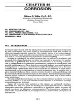
Figure 1.1 shows a straight prismatic bar loaded in tension by opposing forces (P) at each
end. (A prismatic bar has a uniform cross section along its length.) These forces produce
a tensile load along the axis of the bar, which is why it is called axial loading, resulting in
a tensile normal stress in the bar. There is also a corresponding lengthening of the bar. If
these forces were in the opposite direction, then the bar would be loaded in compression,
producing a compressive normal stress and a shortening of the bar.
P
P
Prismatic bar
FIGURE 1.1 Axial loading.
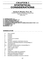
Figure 1.2 shows a riveted joint, where a simple rivet holds two overlapping bars together.
The shaft of the rivet at the interface of the bars is in direct shear, meaning that a shear
stress is produced in the rivet. As the forces (P) increase, the joint will rotate until either
the rivet shears off, or the material around the hole of either bar pulls out.
P
P
Riveted joint
FIGURE 1.2 Direct shear loading.
Figure 1.3 shows a circular shaft acted upon by opposing torques (T ), causing the shaft
to be in torsion. This type of loading produces a shear stress in the shaft, thereby causing
one end of the shaft to rotate about the axis of the shaft relative to the other end.
3
Copyright © 2005 by The McGraw-Hill Companies, Inc. Click here for terms of use.
P1: Shibu
Brown.cls Brown˙C01 January 4, 2005 12:26
4 STRENGTH OF MACHINES
T
T
FIGURE 1.3 Torsion.
Figure 1.4 shows a simply supported beam with a concentrated force (F) located at
its midpoint. This force produces both a bending moment distribution and a shear force
distribution in the beam. At any location along the length (L) of the beam, the bending
moment produces a normal stress, and the shear force produces a shear stress.
B
L
F
A
L
/2
FIGURE 1.4 Bending.
The beam shown in Fig. 1.4 will deflect downward along its length; however, unlike axial
loading, direct shear loading, and torsion that have a single equation associated with their
deformation, there is not a single equation for the deformation or deflection of any beam
under any loading. Each beam configuration and loading is different. A detailed discussion
of 15 different beam configurations is presented in Chap. 2, complete with reactions, shear
force and bending moment distributions, and deflection equations.
1.2 AXIAL LOADING
The prismatic bar shown in Fig. 1.5 is loaded in tension along its axis by the opposing
forces (P) at each end. Again, a prismatic bar has a uniform cross section, and therefore a
constant area (A) along its length.
P
P
Prismatic bar
FIGURE 1.5 Axial loading.
Stress. These two forces produce a tensile load along the axis of the bar, resulting in a
tensile normal stress (σ ) given by Eq. (1.1).
σ =
P
A
(1.1)
As stress is expressed by force over area, the unit is given in pound per square inch (psi)
in the U.S. Customary System, and in newton per square meter, or pascal (Pa), in the metric
system.
P1: Shibu
Brown.cls Brown˙C01 January 4, 2005 12:26
FUNDAMENTAL LOADINGS 5
U.S. Customary SI/Metric
Example 1. Determine the normal stress in a
square bar with side (a) loaded in tension with
forces (P), where
P = 12 kip = 12,000 lb
a = 2in
Example 1. Determine the normal stress in a
square bar with side (a) loaded in tension with
forces (P), where
P = 55 kN = 55,000 N
a = 5cm= 0.05 m
solution
solution
Step 1. Calculate the cross-sectional area (A)
of the bar.
Step 1. Calculate the cross-sectional area A of
the bar.
A = a
2
= (2in)
2
= 4in
2
A = a
2
= (0.05 m)
2
= 0.0025 m
2
Step 2. From Eq. (1.1), calculate the normal
stress (σ ) in the bar.
Step 2. From Eq. (1.1), calculate the normal
stress (σ ) in the bar.
σ =
P
A
=
12,000 lb
4in
2
= 3,000 lb/in
2
= 3.0 kpsi
σ =
P
A
=
55,000 N
0.0025 m
2
= 22,000,000 N/m
2
= 22 MPa
Example 2. Calculate the minimum cross-
sectional area (A
min
) needed for a bar axially
loaded in tension by forces (P) so as not to ex-
ceed a maximum normal stress (σ
max
), where
P = 10 kip = 10,000 lb
σ
max
= 36,000 psi
Example 2. Calculate the minimum cross-
sectional area (A
min
) needed for a bar axially
loaded in tension by forces (P) so as not to ex-
ceed a maximum normal stress (σ
max
), where
P = 45 kN = 45,000 N
σ
max
= 250 MPa
solution
solution
Step 1. Start with Eq. (1.1) where the normal
stress (σ) is maximum and the area (A) is min-
imum to give
Step 1. Start with Eq. (1.1) where the normal
stress (σ) is maximum and the area (A) is min-
imum to give
σ
max
=
P
A
min
σ
max
=
P
A
min
Step 2. Solve for the minimum area (A
min
). Step 2. Solve for the minimum area (A
min
).
A
min
=
P
σ
max
A
min
=
P
σ
max
Step 3. Substitute for the force (P) and the
maximum normal stress.
Step 3. Substitute for the force (P) and the
maximum normal stress.
A
min
=
10,000 lb
36,000 lb/in
2
= 0.28 in
2
A
min
=
45,000 N
250 ×10
6
N/m
2
= 0.00018 m
2
Strain. The axial loading shown in Fig. 1.6 also produces an axial strain (ε), given by
Eq. (1.2).
ε =
δ
L
(1.2)
where (δ) is change in length of the bar and (L) is length of the bar.
P1: Shibu
Brown.cls Brown˙C01 January 4, 2005 12:26
6 STRENGTH OF MACHINES
P
P
Prismatic bar
FIGURE 1.6 Axial loading.
Strain is a dimensionless quantity and does not have a unit if the change in length ε and
the length (L) are in the same units. However, if the change in length (δ) is in inches or
millimeters, and the length (L) is in feet or meters, then the strain (ε) will have a unit.
U.S. Customary SI/Metric
Example 3. Calculate the strain (ε) for a
change in length (δ) and a length (L), where
δ = 0.015 in
L = 5ft
Example 3. Calculate the strain (ε) for a
change in length (δ) and a length (L), where
δ = 0.038 cm
L = 1.9 m
solution
solution
Step 1. Calculate the strain (ε) from Eq. (1.2).
Step 1. Calculate the strain (ε) from Eq. (1.2).
ε =
δ
L
=
0.015 in
5ft
= 0.003 in /ft × 1 ft /12 in
= 0.00025 in /in = 0.00025
ε =
δ
L
=
0.038 cm
1.9m
= 0.02 cm /m × 1 m /100 cm
= 0.0002 m /m = 0.0002
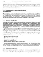
Stress-Strain Diagrams. If the stress (σ) is plotted against the strain (ε) for an axially
loaded bar, the stress-strain diagram for a ductile material in Fig. 1.7 results, where A is
proportional limit, B elastic limit, C yield point, D ultimate strength, and F fracture point.
s
A
B, C
D
F
e
E
FIGURE 1.7 Stress-strain diagram (ductile material).
The stress-strain diagram is linear up to the proportional limit, and has a slope (E) called
the modulus of elasticity. In this region the equation of the straight line up to the proportional
limit is called Hooke’s law, and is given by Eq. (1.3).
σ = E ε (1.3)
The numerical value for the modulus of elasticity (E) is very large, so the stress-strain
diagram is almost vertical to point A, the proportional limit. However, for clarity the hori-
zontal placement of point A has been exaggerated on both Figs. 1.7 and 1.8.
P1: Shibu
Brown.cls Brown˙C01 January 4, 2005 12:26
FUNDAMENTAL LOADINGS 7
A
,
B
,
C
,
D
,
F
s
e
E
FIGURE 1.8 Stress-strain diagram (brittle material).
The stress-strain diagram for a brittle material is shown in Fig. 1.8, where points A, B,
C, D, and F are all at the same point. This is because failure of a brittle material is virtually
instantaneous, giving very little if any warning.
Poisson’s Ratio. The law of conservation of mass requires that when an axially loaded
bar lengthens as a result of a tensile load, the cross-sectional area of the bar must reduce
accordingly. Conversely, if the bar shortens as a result of a compressive load, then the cross-
sectional area of the bar must increase accordingly. The amount by which the cross-sectional
area reduces or increases is given by a material property called Poisson’s ratio (ν), and is
defined by Eq. (1.4).
ν =−
lateral strain
axial strain
(1.4)
where the lateral strain is the change in any lateral dimension divided by that lateral dimen-
sion. For example, if the lateral dimension chosen is the diameter (D) of a circular rod, then
the lateral strain could be calculated using Eq. (1.5).
lateral strain =
D
D
(1.5)
The minus sign in the definition of Poisson’s ratio in Eq. (1.4) is needed because the
lateral and axial strains will always have opposite signs, meaning that a positive axial strain
produces a negative lateral strain, and a negative axial strain produces a positive lateral
strain. Strangely enough, Poisson’s ratio is bounded between a value of zero and a half.
0 ≤ ν ≤
1
2
(1.6)
Again, this is a consequence of the law of conservation of mass that must not be violated
during deformation, meaning a change in shape. Values of both the modulus of elasticity (E)
and Poisson’s ratio (ν) are determined by experiment and can be found in Marks’ Standard
Handbook for Mechanical Engineers.