EARTH STATION TECHNOLOGY
Bạn đang xem bản rút gọn của tài liệu. Xem và tải ngay bản đầy đủ của tài liệu tại đây (2.09 MB, 244 trang )
EARTH STATION
TECHNOLOGY
Revision 5, June 1999
FOREWORD
This handbook has been prepared under INTELSAT’s Assistance and
Development Program (IADP). It is also used as a reference handbook for courses
on Earth station communications technology organized under the INTELSAT
Signatory Training Program (ISTP).
The handbook is updated from time to time. Address any questions or suggestions
to:
Manager
Application Support and Training (IADP/ISTP)
Mail Stop 20B
INTELSAT
3400 International Drive, NW
Washington, DC 20008-3098
Telephone:
Facsimile:
Telex:
International Telex:
First printed:
Revision 1:
Revision 2:
Revision 3:
Revision 4:
Revision 5:
+1 202 944 7070
+1 202 944 8214
(WUT) 89-2707
(WUI) 64290
April 1983
January 1984
September 1985
November 1987
March 1995
June 1999
INTELSAT Earth Station Technology
Table of Contents
CONTENTS
Chapter 1 - SATELLITE ORBITS ..................................................... 1
1.1 Introduction ............................................................................................................ 1
1.2 Orbits ..................................................................................................................... 2
1.3 Stabilization............................................................................................................ 5
1.4 Position .................................................................................................................. 5
1.5 Frequency Bands ................................................................................................... 5
1.6 Time Delay............................................................................................................. 8
1.7 Geographical Advantage........................................................................................ 9
1.8 Path Loss ............................................................................................................... 9
1.9 Sun Interference................................................................................................... 11
1.10 Tropospheric Scintillation ..................................................................................... 12
Chapter 2 - INTELSAT SATELLITES............................................. 13
2.1
2.2
2.3
2.4
INTELSAT SYSTEM ............................................................................................ 13
SATELLITE DESIGN ........................................................................................... 16
INTELSAT SATELLITE SERIES.......................................................................... 25
Summary.............................................................................................................. 44
Chapter 3 - EARTH STATION ANTENNAS .................................. 45
3.1
3.2
3.3
3.4
3.5
3.6
3.7
3.8
3.9
Introduction .......................................................................................................... 45
Antenna Configurations........................................................................................ 45
Antenna Mounts ................................................................................................... 50
Dish Antennas Geometry ..................................................................................... 52
Antenna Parameters ............................................................................................ 52
Antenna Standards .............................................................................................. 57
Entry of Earth Stations into the INTELSAT System.............................................. 60
INTELSAT Documentation................................................................................... 61
Earth Station Site Selection.................................................................................. 64
Chapter 4 - ANTENNA TRACKING............................................... 73
4.1
4.2
4.3
4.4
4.5
4.6
4.7
Introduction .......................................................................................................... 73
Satellite Stationkeeping........................................................................................ 73
Look Angles to Geostationary Satellites............................................................... 76
IESS 412.............................................................................................................. 79
Antenna Gain Rolloff ............................................................................................ 80
Tracking Systems................................................................................................. 82
Student Question Paper ....................................................................................... 91
Chapter 5 - POWER AMPLIFIERS................................................ 93
5.1
5.2
5.3
5.4
5.5
5.6
Introduction .......................................................................................................... 93
Power Rating........................................................................................................ 93
Types of Power Amplifiers.................................................................................... 93
Power Combining (Multiplexing)......................................................................... 118
Common Terminology Used with Power Amplifiers ........................................... 123
Student Question Paper ..................................................................................... 124
Last Updated: 04 June 1999
Verify document currency before use.
Page i of 244
Doc. No.: ESTECH-1999-HNDBK-103
Pub. Rel. No.: 5
INTELSAT Earth Station Technology
Table of Contents
CONTENTS (cont.)
Chapter 6 - LOW-NOISE AMPLIFIERS....................................... 125
6.1 Introduction ........................................................................................................ 125
6.2 Noise.................................................................................................................. 125
6.3 FET Amplifiers.................................................................................................... 128
Chapter 7 -FREQUENCY CONVERTERS................................... 131
7.1
7.2
7.3
7.4
Introduction ........................................................................................................ 131
Frequency Conversion Principle ........................................................................ 131
Frequency Converters........................................................................................ 133
Student Question Paper ..................................................................................... 142
Chapter 8 - EARTH STATION TEST EQUIPMENT
and MEASUREMENT UNITS ...................................................... 145
8.1
8.2
8.3
8.4
8.5
8.6
8.7
8.8
Introduction ........................................................................................................ 145
Power Meter....................................................................................................... 145
Frequency Counter ............................................................................................ 147
Microwave Link Analyzer.................................................................................... 148
BER Test Set ..................................................................................................... 154
Spectrum Analyzer............................................................................................. 156
Measurement Units ............................................................................................ 160
Student Question Paper ..................................................................................... 163
Chapter 9 - EARTH STATION DESIGN ...................................... 165
9.1
9.2
9.3
9.4
9.5
Introduction ........................................................................................................ 165
Performance Objectives..................................................................................... 165
Link Budget ........................................................................................................ 165
Examples ........................................................................................................... 183
Student Question Paper ..................................................................................... 190
Chapter 10 - ENGINEERING SERVICE CIRCUIT (ESC)
and POWER PLANT................................................................... 191
10.0 Introduction ...................................................................................................... 191
10.1 Student Question Paper ................................................................................... 213
APPENDIX A -WAVEGUIDES AND FEEDS................................ 215
Last Updated: 04 June 1999
Verify document currency before use.
Page ii of 244
Doc. No.: ESTECH-1999-HNDBK-103
Pub. Rel. No.: 5
INTELSAT Earth Station Technology
Chapter 1 –Satellite Orbits
CHAPTER 1
SATELLITE ORBITS
1.1
Introduction
The concept of a global telecommunications system using satellites
was put forward first in an article for the British Magazine "Wireless
World" in May 1945 by the science fiction author, Arthur C. Clarke.
A brief extract from this article addressing the issue of orbital
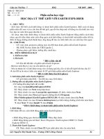
location for geostationary communications satellites is quoted below.
"All these problems can be solved by the use of a chain of
space-stations with an orbital period of 24 hours, which would
require them to be at a distance of 42,000 Km from the center of the
Earth. There are a number of possible arrangements for such a
chain but that shown (Figure 1.1) is the simplest. The stations would
lie in the Earth’s equatorial plane and would thus always remain
fixed in the same spots in the sky, from the point of view of terrestrial
observers. Unlike all other heavenly bodies they would never rise
nor set. This would greatly simplify the use of directive receivers
installed on the Earth."
"The following longitudes are provisionally suggested for the stations
to provide the best service to the inhabited portions of the globe,
though all parts of the planet will be covered.
30° E - Africa and Europe
150° E - China and Oceania
90° W - The Americas
Last Updated: 04 June 1999
Verify document currency before use.
Page 1 of 244
Doc. No.: ESTECH-1999-HNDBK-103
Pub. Rel. No.: 5
INTELSAT Earth Station Technology
Chapter 1 –Satellite Orbits
Figure 1.1 Arthur Clark’s View of a Global Communications System
Each station would broadcast programs over about a third of the
planet. Assuming the use of a frequency of 3,000 megacycles, a
reflector only a few feet across would give a beam so directive that
almost all the power would be concentrated on the Earth. Arrays a
meter or so in diameter could be used to illuminate single countries if
a more restricted service was required."
1.2
Orbits
Before discussing satellite orbits in more general terms, it is
important to understand the natural laws that control the movement
of satellites. These are based on Kepler’s Laws and state that:
1.
2.
The orbital plane of any Earth satellite must bisect the Earth
centrally.
The Earth must be at the center of any orbit.
There are basically three orbits: polar, equatorial, and inclined. The
shape of the orbit is limited to circular and elliptical.
Any
combination of type and shape is possible but our discussions are
concerned only with the circular polar, the elliptically inclined, and
the circular equatorial orbit as used by INTELSAT, and shown in
Figure 1.2.
Last Updated: 04 June 1999
Verify document currency before use.
Page 2 of 244
Doc. No.: ESTECH-1999-HNDBK-103
Pub. Rel. No.: 5
INTELSAT Earth Station Technology
Chapter 1 –Satellite Orbits
ELLIPTICALLY
INCLINED
CIRCULAR
POLAR
EQUATOR
CIRCULAR EQUATORIAL
Figure 1.2 Three Basic Orbits
Circular Polar
Orbit
This is the only orbit that can provide full global coverage by one
satellite, but requires a number of orbits to do so. In the field of
communications where the instantaneous transfer of information is
required, full global coverage could be achieved with a series of
satellites, where each satellite is separated in time and angle from
its orbit. However, because of economic, technical, and operational
drawbacks, global coverage is not used for telecommunications,
though it is favored for some navigation, meteorological, and land
resource satellite systems.
EllipticallyInclined Orbit
An orbit of this type has unique properties that have been
successfully used by some communications satellite systems,
notably a Soviet domestic system. For this system, the elliptical
orbit has an angle of inclination of 63° and a 12-hour orbit period.
By design, the satellite is made to be visible for eight of its 12-hour
orbit periods to minimize the handover problem while providing
substantial coverage of the Earth's surface. By using three
satellites, suitably phased, continuous coverage of the polar region
that would not be covered by other orbits can be provided.
Last Updated: 04 June 1999
Verify document currency before use.
Page 3 of 244
Doc. No.: ESTECH-1999-HNDBK-103
Pub. Rel. No.: 5
INTELSAT Earth Station Technology
Chapter 1 –Satellite Orbits
Circular
Equatorial Orbit
(Geostationary)
A satellite in a circular orbit at 35,800 km has a period of 24 hours,
and consequently appears stationary over a fixed point on the
Earth’s surface. This orbit is known as the geostationary orbit. The
satellite is visible from one-third of the Earth’s surface, up to the
Arctic Circle, and this orbit is used for the INTELSAT satellite
communications system. Figure 1.3 shows typical coverage areas
for different geostationary satellites.
POR
AOR
IOR
APR
POR
Figure 1.3 INTELSAT Global Network and Coverage Areas
As shown in Figure 1.3, there is a satellite positioned over each
ocean region. In fact, INTELSAT has 19 satellites in the
geostationary orbit, grouped into four regions.
There is a
considerable overlap of some of the beams that enables some
countries to look at satellites in two or three different regions.
Last Updated: 04 June 1999
Verify document currency before use.
Page 4 of 244
Doc. No.: ESTECH-1999-HNDBK-103
Pub. Rel. No.: 5
INTELSAT Earth Station Technology
Chapter 1 –Satellite Orbits
1.3
Stabilization
Stabilization of the satellite is necessary because the Earth is not
truly spherical. The Earth’s tidal motion, the Moon and the Sun have
gravitational effects on the satellite, which tends to make it drift from
its correct position. An orbit that is inclined towards the equatorial
plane produces a sinusoidal variation in longitude, seen from Earth
as motion around an ellipse once every 24 hours. Incorrect velocity
results in incorrect altitude and a drift to the east or to the west.
1.4
Position
The satellite must be maintained in position for its required lifetime
(typically 10 to 15 years). This positioning is regularly corrected to
within ±0.10°. To extend the life of the satellites, less frequent
corrections may be made. For example, keeping the satellite in its
current North-South position is particularly demanding on satellite
fuel reserves. If the North-South positioning is left unchecked, the
satellite will tend to move to a natural position (Inclination) of 15°
away from the geostationary orbit. INTELSAT allows some of its
satellites to increase inclination up to about ± 3 degrees, which
extends the operational life up to 3 years or more. These satellites
are said to be in "inclined orbit".
1.5
Frequency Bands
A communication satellite is basically an electronic communication
package placed in orbit around the Earth. Its prime objective is to
facilitate communications transmission from one point on Earth to
another. The satellite collects the electromagnetic field, and
retransmits the modulated carriers as a downlink.
As the signal levels from the satellite are expected to be very low,
any natural phenomena to facilitate the reception of the incoming
signal must be exploited. Note in Figure 1.4 that between the
frequencies of 2 GHz to 10 GHz the level of the sky noise
diminishes, and this band is known as the "microwave window."
The frequencies allocated to satellite communications are in this
band. Those initially used by INTELSAT were 6 GHz and 4 GHz (Cband). Due to the increased demand for more bandwidth, higher
frequencies of 14 GHZ and 11/12 GHZ (Ku-band) are now being
used. Also, new extensions to the existing bands were required.
Tables 1.1 and 1.2, show the satellite frequency bands, and Figure
1.5 shows the different downlink frequencies for Ku-band according
to the region.
Last Updated: 04 June 1999
Verify document currency before use.
Page 5 of 244
Doc. No.: ESTECH-1999-HNDBK-103
Pub. Rel. No.: 5
INTELSAT Earth Station Technology
Chapter 1 –Satellite Orbits
The operational frequency band of the satellite is divided into small
portions called transponders (it transmits the downlink by
responding to the uplink).
A transponder receives the uplink carriers, amplifies them, converts
them to the correct downlink frequency band and then transmits
them, via high-powered amplifiers, back to Earth.
DEG
KELVIN
1000K
OXYGEN
RESONANCE
60 GHz
SKY TEMPERATURE
GALACTIC
BACKGROUND
100K
WATER VAPOUR
RESONANCE
22 GHz
MICRIWAVE
WINDOW
10K
SKY TEMP
(TOTAL)
ATMOSPHERIC
ABSORPTION
1K
0.5
5
10
50
FREQUENCY GHz
Figure 1.4 Sky-Noise and Frequency Bands
Last Updated: 04 June 1999
Verify document currency before use.
Page 6 of 244
Doc. No.: ESTECH-1999-HNDBK-103
Pub. Rel. No.: 5
INTELSAT Earth Station Technology
Chapter 1 –Satellite Orbits
Table 1.1 INTELSAT Satellite Frequency Bands and Nomenclature (Ku-band)
FREQUENCY BANDS (GHz)
CURRENT
DENOMINATION
14/11 GHz
Ku-band
14/12 GHz
Ku-band
UPLINK
DOWNLINK
BANDWIDTH BANDWIDTH
Shorthand
TYPICAL UTILIZATION
Nomenclature
13.75 – 14.50
(750 MHz)
10.95 - 11.20
(250 MHz)
Satellite series INTELSAT V, V-A, V-A(IBS)
VI, VII, VII-A, VIII, and IX
Lower 11GHz band
Ku-band or Band A
@
11.45 - 11.70
(250 MHz)
Satellite series INTELSAT V, V-A, V-A(IBS)
VI, VII, VII-A, VIII, and IX
Upper 11GHz band
Ku-band or Band B
13.75 – 14.50
(750 MHz)
11.70 - 11.95
(250 MHz)
Satellite series INTELSAT V-A (IBS), VII
VII-A, VIII
Lower 12 GHz band
Ku-band or Band C
12.50 - 12.75
(250 MHz)
Satellite series INTELSAT V-A (IBS), VII
VII-A, VIII
Upper 12 GHz band
Ku-band or Band D
@
@ The frequency band 13.75 - 14.00 GHz was allocated to Fixed Satellite Service by WARC - 92 Resolution 112.
Table 1.2 INTELSAT Satellites Frequency Bands and Nomenclature (C-band)
FREQUENCY BANDS (GHz)
CURRENT
DENOMINATION
6/4 GHz
C-band
UPLINK
DOWNLINK
BANDWIDTH BANDWIDTH
Shorthand
TYPICAL UTILIZATION
Nomenclature
5.925 – 6.425
(500 MHz)
3.700 - 4.200
(500 MHz)
At present the most widely used band
all INTELSAT series.
C – band
5.850 – 6.425
(575 MHz)
3.625 - 4.200
(575 MHz)
75 MHz of band extension, to nominal C-band.
Satellite series INTELSAT VI, VIII, IX & APR-1.
C – band
6.425 – 6.650
3.400 - 3.625
Extended C – Band
C – band
(225 MHz)
(225 MHz)
Last Updated: 04 June 1999
Verify document currency before use.
Added to the nominal C – band in
APR-1 and VIII-A.
Page 7 of 244
extended band
Doc. No.: ESTECH-1999-HNDBK-103
Pub. Rel. No.: 5
INTELSAT Earth Station Technology
REGION 3
REGION 2
FREQUENCY
BAND
(GHZ)
Chapter 1 –Satellite Orbits
REGION 1
REGION 1
10.7 - 11.7
11.7 - 12.5
12.5 - 12.75
REGION 3
REGION 2
10.7 - 11.7
11.7 - 12.2
12.2 - 12.75
REGION 3
10.7 - 11.7
12.5 - 12.75
Figure 1.5 Chart of Regions as defined by the ITU
for Ku-band Downlink
1.6
Time Delay
The total Earth-satellite-Earth path length may be as much as
84,000km thus giving a one-way propagation delay of 250ms. The
effect of this delay on telephone conversations, where a 500ms gap
can occur between one person asking a question and hearing the
other person reply, has been widely investigated, and found to be
less of a problem than had been anticipated. This phenomenon is
minimized with the use of "Echo cancelers". With geostationary
satellites, a two-hop operation is sometimes unavoidable and results
in a delay of over 1 second.
Last Updated: 04 June 1999
Verify document currency before use.
Page 8 of 244
Doc. No.: ESTECH-1999-HNDBK-103
Pub. Rel. No.: 5
INTELSAT Earth Station Technology
Chapter 1 –Satellite Orbits
1.7
Geographical
Advantage
A station which is located near the center of a satellite beam
(footprint), will have an advantage in the received signal compared
to another located at the edge of the same beam of the satellite.
The satellite antenna pattern has a defined beam edge to which the
values of the satellite Equivalent Isotropically Radiated Power
(EIRP), Gain-to-Noise Temperature ratio (G/T), and flux density are
referenced. Therefore, a footprint as shown in Figure 1.6 will have
lines of contours representing a 1 dB incremental toward the beam
center.
1.8
Path Loss
The total path loss for satellites in geostationary orbit depends on
the distance and frequency of operation but is in the order of 200 dB
in C-band and 206 dB in Ku-band.
Last Updated: 04 June 1999
Verify document currency before use.
Page 9 of 244
Doc. No.: ESTECH-1999-HNDBK-103
Pub. Rel. No.: 5
INTELSAT Earth Station Technology
Chapter 1 –Satellite Orbits
+1
+2
+3
+4
BEAM
EDGE
Figure 1.6 Example of Geographical Advantage
Last Updated: 04 June 1999
Verify document currency before use.
Page 10 of 244
Doc. No.: ESTECH-1999-HNDBK-103
Pub. Rel. No.: 5
INTELSAT Earth Station Technology
Chapter 1 –Satellite Orbits
1.9
Sun Interference
Sun interference is due to the satellite, the Sun, and the Earth
station antenna being aligned, causing the antenna to receive solar
noise, as shown in Figure 1.7.
The Sun represents a transmitter with significantly more power than
the satellite, and the solar noise will overwhelm the signals coming
from the satellite, causing a total loss of traffic.
Figure 1.7 Sun Interference
Last Updated: 04 June 1999
Verify document currency before use.
Page 11 of 244
Doc. No.: ESTECH-1999-HNDBK-103
Pub. Rel. No.: 5
INTELSAT Earth Station Technology
Chapter 1 –Satellite Orbits
This degradation occurs twice a year during the spring and autumn
and lasts for 5 to 6 days, with the degradation on the first and last
days lasting for a few minutes but no more than 15, depending on
location. INTELSAT advises each station of when Sun interference
can be expected and its duration as calculated for each day.
If continuous tracking is used at the Earth station, it is the duty of the
technician to deactivate the continuous tracking during the periods of
interference to ensure that the dish does not track the Sun instead of
the satellite.
It is normal policy to advise priority customers whose traffic is
susceptible to disturbances, i.e., banks, airline offices etc., well in
advance to minimize the effects of the outage.
1.10
Tropospheric
Scintillation
At unpredictable times the levels of receive signals from the satellite
rapidly fluctuate up and down. This is called scintillation. Scintillation
is brought about by the turbulent mixing of air mass at different
temperatures and humidities, and by the random addition of
particles such as rain, ice, and moisture. Changes of up to 12 dB
have been recorded across the 500 MHz satellite band for up to 2 or
3 hours, and may be observed at one Earth station while a
neighboring Earth station at a distance of 200km is not being
affected.
Scintillation is caused by variations in amplitude and phase of the
microwave signal as it propagates along the slant path through the
atmosphere. The air masses that comprise the atmosphere are not
homogenous causing the radio refractive index of the air mass to
vary with time and position within the mass.
Severe scintillations can adversely affect the tracking capabilities of
the Earth station and preventive action (such as program or memory
tracking) may have to be taken.
Last Updated: 04 June 1999
Verify document currency before use.
Page 12 of 244
Doc. No.: ESTECH-1999-HNDBK-103
Pub. Rel. No.: 5
INTELSAT Earth Station Technology
Chapter 2 – INTELSAT Satellites
CHAPTER 2
INTELSAT SATELLITES
2.1
INTELSAT
SYSTEM
Satellites’
Deployment
INTELSAT space segment currently comprises 19 satellites in orbit,
making the INTELSAT system the most comprehensive system for
global communications. It currently includes INTELSAT V/VA, VI,
VII/VIIA, and VIII series satellites. In the near future, the system will
also have APR-1 and INTELSAT IX.
Figure 2.1 Deployment of INTELSAT Satellites
Last Updated: 04 June 1999
Verify document currency before use.
Page 13 of 244
Doc. No.: ESTECH-1999-HNDBK-103
Pub. Rel. No.: 5
INTELSAT Earth Station Technology
Chapter 2 – INTELSAT Satellites
Coverage Areas
Atlantic Ocean Region (AOR): Covers the Americas, the
Caribbean, Europe, the Middle East, India, and Africa with satellites
at orbital locations ranging from 304.5° E to 359° E.
Indian Ocean Region (IOR): Covers Europe, Africa, Asia, the
Middle East, India, and Australia with satellites at orbital locations
ranging from 33° E to 66° E.
Pacific Ocean Region (POR): Covers Asia, Australia, the Pacific
Rim, and the Western part of North America with satellites at orbital
locations ranging from 174° E to 180° E.
Asia Pacific Region (APR): As three ocean regions no longer meet
customer demand, a fourth region, Asia Pacific, was introduced and
began service in 1993 using INTELSAT 501. This new region,
highlighted in Figure 2.2, provides an improved connectivity for the
western Pacific Rim and the Asian land mass as well as for all parts
of Central and Eastern Europe, Japan, and Australia with one
satellite, currently located at 72° E. A new satellite, APR1 at 83° E
will be available for operation in 1999.
Last Updated: 04 June 1999
Verify document currency before use.
Page 14 of 244
Doc. No.: ESTECH-1999-HNDBK-103
Pub. Rel. No.: 5
INTELSAT Earth Station Technology
Chapter 2 – INTELSAT Satellites
APR
POR
AOR
IOR
POR
Figure 2.2 INTELSAT Coverage Areas
Upcoming
Launches
The following satellites will be deployed in the near future to
replace the satellites ending their projected lifetime.
Table 2.1 Upcoming Launches
New Satellite
APR-1 @ 83°E
IS-901 @ 60°E
IS-902 @ 62°E
IS-903 @ 335.5°E
IS-904 @ 325.5°E
Last Updated: 04 June 1999
Verify document currency before use.
Replaced Satellite
IS-604 @ 60°E
IS-902 @ 62°E
IS-603 @ 335.5°E
IS-601 @ 325.5°E
Page 15 of 244
Launch Window
1999
2000
2000
2001
2001
Doc. No.: ESTECH-1999-HNDBK-103
Pub. Rel. No.: 5
INTELSAT Earth Station Technology
Chapter 2 – INTELSAT Satellites
2.2
SATELLITE
DESIGN
SatellitesSeries Overview
Figure 2.3 displays INTELSAT communications satellites. Since
INTELSAT’s inception in 1965, traffic growth has been extremely
rapid. Invariably, the capacity offered by any individual satellite has
been filled quickly, resulting in the requirement for larger satellites
with increased capacity every few years. This has meant that
INTELSAT has only just been able to keep pace with demand, but to
do this each successive satellite has had to use a new technique to
obtain increased channel capacity within the limitations imposed by
satellite design.
Some of the limitations affecting the design include:
1.
2.
3.
A maximum weight that a particular launch vehicle can carry
into orbit.
Bandwidth allocated by the ITU for satellite communications.
This is presently 875 MHz in the C-band and 750 MHz in the
Ku-band.
A maximum radiofrequency (RF) power such that terrestrial
microwave links using the same frequencies are not
affected, but one that still provides sufficient power for
realistic signal-to-noise ratios at the receiving Earth stations.
Table 2.2 shows INTELSAT satellites since Early Bird. A brief
description of each type of satellite used by INTELSAT follows,
showing the continuous improvements in design and capacity.
Last Updated: 04 June 1999
Verify document currency before use.
Page 16 of 244
Doc. No.: ESTECH-1999-HNDBK-103
Pub. Rel. No.: 5
INTELSAT Earth Station Technology
INTELSAT I
INTELSAT II
Chapter 2 – INTELSAT Satellites
INTELSAT III
INTELSAT V
INTELSAT IV
INTELSAT IV-A
INTELSAT VI
INTELSAT VII
INTELSAT VIII
INTELSAT IX
Figure 2.3 INTELSAT Satellite Series
Last Updated: 04 June 1999
Verify document currency before use.
Page 17 of 244
Doc. No.: ESTECH-1999-HNDBK-103
Pub. Rel. No.: 5
INTELSAT Earth Station Technology
Chapter 2 – INTELSAT Satellites
Table 2.2 Summary of INTELSAT Satellites’ Features
INTELSAT
TOTAL
RF
PRIME
WEIGHT
STABILI-
Satellite
RF BW
BAND
POWER
(Kg).
ZATION
LIFE
Series
(MHz)
TYPE
(years)
I
50
C
45
SPIN
1.5
(Watts)
45
Design
NEW FEATURE
First satellite
services
for
international
telephony
II
125
C
75
45
SPIN
3
III
450
C
120
300
SPIN
5
Telephony plus TV capacity.
The first global satellite system.
IV
480
C
460
720
SPIN
7
SCPC service and the RF band divided into 36
MHz transponders.
IV-A
800
C
595
795
SPIN
7
Frequency reuse by spatial isolation
V
2200
C and Ku
175
970
3-AXES
7
Frequency reuse by polarization isolation, Kuband package and cross-strapped operation.
V-A
2250
C and Ku
1475
970
3-AXES
7
Frequency reuse for
steerable spot beams
VI
3300
C and Ku
2100
1800
SPIN
10
SS-TDMA operation and Solid State Power
Amplifiers (SSPAs) as output amplifiers in
some beams.
VII
2432
C and Ku
4000
1437
3-AXES
10.9
SSPAs in all C-band transponders; switchable
transponder and enhanced U/L connectivity in
Zone Beams; 12 GHz D/L capability; enhanced
Ku-Spot 2 coverage for POR
VII-A
3160
C and Ku
5000
1823
3-AXES
10.9
Linearized Traveling Wave Tube Amplifiers
(LTWTAs) and paralleled LTWTAs in Ku-band
for a high power mode; Ku- to C-band
connectivity
VIII
2550
C and Ku
5100
1587
3-AXES
10
Polarization reversal option in Ku-band; TV
Broadcast mode in Zone Beams for a West
Quasi-Hemi coverage; flexible transponder
activation for 6 out of 10 Channels in Ku-band
APR
396
Extended
C
2200
1118
3-AXES
12
Linear polarization, extended C-band, higher
EIRP
IX
3456
C and Ku
8085
1900
3-AXES
13
Selectable split uplink in Global Channel 12 for
SNG; selectable split uplink in Hemi Channel 9
for DAMA. Flexible transponder activation for
12 out of 16 channels in Ku-band. Equipped
with an overdrive control for Ku-band
transponders.
global
beams
Satellite
Stabilization
INTELSAT communication satellites use two basic designs:
1.
Cylindrical spin-stabilized
2.
3-Axes stabilized
Last Updated: 04 June 1999
Verify document currency before use.
Page 18 of 244
Doc. No.: ESTECH-1999-HNDBK-103
Pub. Rel. No.: 5
and
INTELSAT Earth Station Technology
Chapter 2 – INTELSAT Satellites
ROTATIONAL
SPEED
30 r.p.m.
Figure 2.4 Cylindrical Spin-Stabilized
Y - AXIS
ROTABLE
SOLAR PANELS
X - AXIS
Z - AXIS
Figure 2.5 Three-Axes Stabilized
Cylindrical
Spin-Stabilized
The satellite in Figure 2.4 is cylindrical in shape, and is made to
rotate at approximately 30 rpm to maintain orbital stability.
Last Updated: 04 June 1999
Verify document currency before use.
Page 19 of 244
Doc. No.: ESTECH-1999-HNDBK-103
Pub. Rel. No.: 5