motor control centers
Bạn đang xem bản rút gọn của tài liệu. Xem và tải ngay bản đầy đủ của tài liệu tại đây (5.55 MB, 80 trang )
1
Table of Contents
Introduction 2
Motor Control 4
Power Supplies 8
Design Standards 12
Need for Circuit Protection 13
Motor Control Centers 21
tiastar MCC Construction 32
tiastar Arc Resistant MCC 43
Combination Motor Control Units 47
Motor Starters 54
Pilot Devices 60
Circuit Breakers 61
Other Types of Devices in MCCs 62
Smart MCCs 65
tiastar Smart MCCs 70
Review Answers 77
Final Exam 80
2
Introduction
Welcome to another course in the STEP series, Siemens
Technical Education Program, designed to prepare our
distributors to sell Siemens Industry, Inc. products more
effectively. This course covers Basics of Motor Control
Centers.
Upon completion of Basics of Motor Control Centers, you
should be able to:
• Explain the role of motor control centers (MCCs) in a
distribution system
• Define an MCC according to NEMA and UL
• Explain the need for circuit protection
• Identify various components of a MCC
• Explain the difference between the various classifications
and types of motor control center wiring
• Describe key features of the tiastar MCCs
• Describe key features of tiastar arc resistant MCCs
• Explain the term smart MCC
• Identify key advantages of smart MCCs
• Describe key features of tiastar smart MCCs
This knowledge will help you better understand customer
applications. In addition, you will be better prepared to describe
motor control products to customers. You should complete
Basics of Electricity and Basics of Control Components
before attempting Basics of Motor Control Centers.
After you have completed this course, if you wish to determine
how well you have retained the information covered, you can
complete a final exam online as described later in this course. If
you pass the exam, you will be given the opportunity to print a
certificate of completion.
3
Siemens is a trademark of Siemens AG. Product names
mentioned may be trademarks or registered trademarks of their
respective companies. Specifications are subject to change
without notice.
NFPA70®, National Electrical Code® and NEC® are registered
trademarks of the National Fire Protection Association, Quincy,
MA 02169.
NEMA® is a registered trademark and service mark of the
National Electrical Manufacturers Association, Rosslyn, VA
22209.
Underwriters Laboratories Inc. and UL are registered
trademarks of Underwriters Laboratories Inc., Northbrook, IL
60062-2096.
Other trademarks are the property of their respective owners.
4
Motor Control
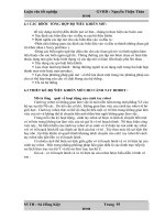
Power distribution systems used in large commercial and
industrial applications can be complex. Power may be
distributed through switchgear, switchboards, transformers,
and panelboards. Power distributed throughout a commercial
or industrial application is used for a variety of applications such
as heating, cooling, lighting, and motor-driven machinery. Unlike
other types of power distribution equipment, which are used
with a variety of load types, motor control centers primarily
control the distribution of power to electric motors.
Feeder Busway
Motor Control Center
Switchboard
Panelboard
Transformer
Panelboard
480 VAC
480 VAC
480 VAC
120 VAC
480 VAC
480 VAC
From Utility
Outdoor
Feeder
Busway
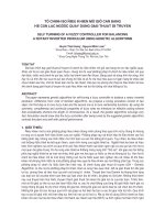
Basic Motor Control Wherever motors are used, they must be controlled. In Basics
of Control Components you learned how various control
products are used to control the operation of motors. For
example, the most basic type of AC motor control, involves
turning the motor on and off. This is often accomplished using a
motor starter made up of a contactor and an overload relay.
The contactor’s contacts are closed to start the motor and
opened to stop the motor. This is done electromechanically
and often requires using start and stop pushbuttons and other
devices wired to control the contactor.
5
The overload relay protects the motor by disconnecting power
to the motor when an overload condition exists. Although the
overload relay provides protection from overloads, it does not
provide short-circuit protection for the wiring supplying power
to the motor. For this reason, a circuit breaker or fuses are also
used.
Circuit Breaker
L1
L2
L3
Motor Starter
Contactor
Overload Relay
Motor
OL
OL
OL
M
M
M
Start
Pushbutton
Stop
Pushbutton
Ma
M
Auxiliary Contactor Contact
(Holding Circuit)
Contactor Coil
Overload Contact
1
5
0
A
OFF
O
I
ON
Ty
pe/T
ip
o
N
D
G
Frame DG
AC Motor
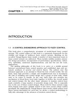
Typically one motor starter controls one motor. When only a
few geographically dispersed AC motors are used, the circuit
protection and control components may be in an enclosure
mounted close to the motor.
Short Circiut
Protection
Disconnect
Motor Starter
OFF
ON
OFF
ST
AR
T
STOP
6
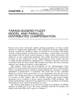
Motor Control Centers In many commercial and industrial applications, quite a few
electric motors are required, and it is often desirable to control
some or all of the motors from a central location. The apparatus
designed for this function is the motor control center (MCC).
Motor control centers are simply physical groupings of
combination starters in one assembly. A combination starter is
a single enclosure containing the motor starter, fuses or circuit
breaker, and a device for disconnecting power. Other devices
associated with the motor, such as pushbuttons and indicator
lights, may also be included.
Motor Control Center
Siemens tiastar tiastar (pronounced tie-star) is the trade name for Siemens
Motor Control Centers motor control centers. tiastar motor control centers offer a
number of innovative features as described throughout this
course.
tiastar Motor Control Center
7
Advantages of Some of the advantages of using tiastar motor control
Siemens tiastar MCCs centers are:
• Ruggedness and reliability
• Reduced time needed for installation and startup
• Space saving design
• Excellent component selection
• Simplicity in adding special components
• Ease of future modifications.
TIA The TIA portion of the tiastar name stands for Totally
Integrated Automation. TIA is more than a concept. It is a
strategy developed by Siemens that emphasizes the seamless
integration of automation, networking, drive, and control
products. The TIA strategy is the cornerstone of development
for a wide variety of Siemens products.
TIA is important not just because it simplifies the engineering,
startup, and maintenance of systems developed using Siemens
products, but also because it lowers the life-cycle costs for
systems incorporating these products. Additionally, by reducing
the engineering and startup time and expense for systems, TIA
helps Siemens customers reduce time to market and improve
overall financial performance.
8
Power Supplies
The major source of electrical power used by motor control
centers is an AC generator located at a power generating
facility. AC generators operate on the theory of electromagnetic
induction. This simply means that when conductors are
moved through a magnetic field, a voltage is induced into the
conductors. A basic generator consists of a magnetic field, an
armature, slip rings, brushes, and some type of resistive load.
An armature is any number of conductive wires (conductors)
wound in loops which rotate through the magnetic field. For
simplicity, one loop is shown.
If the rotation of the AC generator were tracked through a
complete revolution of 360°, it could be seen that during
the first quarter of a revolution voltage would increase until
it reached a maximum positive value at 90°. Voltage would
decrease during the second quarter of revolution until it reached
zero at 180°. During the third quarter of a revolution voltage
would increase in the opposite direction until it reached a
maximum negative value at 270°. During the last quarter of a
revolution voltage would decrease until it reached zero at 360°.
This is one complete cycle or one complete alternation between
positive and negative.
9
If the armature of the simple two-pole AC generator shown
here rotates 3600 times per minute (3600 RPM), the generator
produces 60 cycles of voltage per second, or 60 hertz (Hz). If
the generator had four poles, it would generate the needed
60 Hz with a rotational speed of 1800 RPM.
Three-Phase Voltage In most large commercial and industrial motor applications,
three-phase power is used. In a three-phase system, the
generator produces three voltages. Each voltage phase rises
and falls at the same frequency (60 Hz in the U.S., 50 Hz in
many other countries); however, the phases are offset by 120°
from each other.
Motor control centers receive this power through complex
distribution systems which include power distribution lines and
related equipment. Transformers used with three-phase power
require three interconnected coils in both the primary and the
secondary. These transformers can be connected in either a
wye or a delta configuration. The type of transformer and the
actual voltage depend on the requirements and capability of the
power company and the needs of the customer. The following
illustration shows examples of the secondary windings of
wye and delta transformers. Keep in mind that these are
only examples and other transformer secondary voltages are
possible.
10
Motor Rotation Three-phase voltage is used throughout large commercial and
industrial facilities to run AC motors. An AC motor is made up
of a stationary member, called a stator, and a rotating member,
called a rotor. Three-phase AC power is applied to the stator
through the power connections.
Stator
Rotor
Power Connections
The direction a three-phase AC motor rotor turns depends
on the phase sequence of the incoming power supply. In the
following example, L1 (A) is connected to motor lead T1, L2 (B)
is connected to motor lead T2, and L3 (C) is connected to motor
lead T3. When power is applied through the “F” contacts, the
motor turns in a clockwise (forward) direction.
However, if any two of the three power supply leads are
reversed, the motor runs in the opposite direction. In the
following example, when the F contacts open and the R
contacts close, L1 (A) is connected to motor lead T3, L2 (B) is
connected to motor lead T2, and L3 (C) is connected to motor
lead T1. (L1 and L3 have been reversed.) As a result, the motor
runs in the counterclockwise (reverse) direction.
11
Many applications are designed for forward and reverse
operation. An overhead crane, for example, might use the
forward direction to raise the crane and reverse direction to
lower the crane.
Overhead Crane
Review 1
1. Which of the following is a advantage of using a tiastar
motor control center?
a. Ruggedness and reliability
b. Reduced time needed for installation and startup
c. Space saving design
d. All the above
2. The TIA portion of the tiastar name stands for ______.
3. In most large commercial and industrial motor
applications, ________-phase power is used.
4. Motor rotation of a three-phase AC induction motor
can be reversed by reversing any ________ of the three
power supply leads.
12
Design Standards
Although several organizations are involved in establishing
standards for the design, construction, and application of motor
control centers, the primary standards discussed in this book
were established by UL, NEMA, and NFPA. The following
organizations have established standards which may be applied
to motor control centers. It is beyond the scope of this course
to cover every standard; however, reference will be made
throughout the course to important standards with which
Siemens motor control centers comply.
UL Underwriters Laboratories (UL) is a private company that is
nationally recognized as an independent testing laboratory. UL
tests products for safety, and products that pass UL tests can
carry a UL mark. Siemens motor control centers are designed
to UL 845 standards.
NEMA The National Electrical Manufacturers Association (NEMA)
is an organization that, among other things, develops standards
for electrical equipment.
NFPA The National Fire Protection Association (NFPA) is a
nonprofit organization which publishes the National Electrical
Code® (NEC®). The intent of the NEC® is to describe safe
electrical practices.
IEC The International Electrotechnical Commission (IEC)
is an organization based in Geneva, Switzerland with over
50 member nations. IEC writes standards for electrical and
electronic equipment practices.
13
Need for Circuit Protection
Some of the components described in this course are designed
to protect circuits and/or motors from overcurrents. In order
to understand these components, you must have a clear
understanding of what an overcurrent condition is and why
overcurrent protection is needed.
Current and Temperature To begin with, current flow always generates heat. The amount
of heat generated is proportional to both the amount of current
flow and the resistance of the conductive path. Keep in mind
that conductors can be damaged by excess heat. For that
reason, each conductor has a continuous current rating, also
called its ampacity.
Excessive current is referred to as overcurrent. An overcurrent
may result from a short circuit, overload, or ground fault. The
first two types of overcurrent conditions are pertinent to this
discussion.
Normal Current Flow
Excessive Current Flow
14
Overloads An overload occurs when too many devices are operated on
a single circuit or when electrical equipment is made to work
harder than its rated capabilities. In the following illustration, a
package has become jammed on a conveyor, causing the motor
to work harder and draw more current. Because the motor is
drawing more current, it heats up. Damage will occur to the
motor in a short time if the problem is not corrected or if the
circuit is not shut down by an overcurrent protection device.
Conductor Insulation Motors, of course, are not the only devices that require circuit
protection for an overload condition. Every circuit requires some
form of protection against overcurrent. Heat is one of the major
causes of insulation failure of any electrical component. High
levels of heat to insulated wire can cause the insulation to
breakdown, melt, or flake off, exposing conductors.
Insulation Affected by Heat
Good Insulation
15
Short Circuits When two bare conductors touch, a short circuit occurs. When
a short circuit occurs, resistance drops to almost zero. Short
circuit current can be thousands of times higher than normal
operating current.
Ohm’s Law demonstrates the relationship of current, voltage,
and resistance. For example, a 240 volt motor with 24 Ω (ohms)
of resistance would normally draw 10 amperes of current.
When a short circuit develops, resistance drops. If resistance
drops to 24 milliohms, current will be 10,000 amperes.
Short-Circuit Current on When a short circuit occurs, current will continue to flow
Unprotected Electrical in an unprotected electrical circuit. The peak short-circuit
Circuits current of the first cycle is the greatest and is referred to as
peak let-thru current (IP). The force of this current can cause
damage to wires and circuit components.
16
Associated with the peak let-thru current is peak let-thru
energy (I
2
t). For an unprotected circuit, this energy is often
capable of dramatic destruction of equipment and is a serious
safety concern.
Short-Circuit Current on Fortunately, if a circuit has a properly applied overcurrent
Protected Electrical Circuits protection device, the device will open the circuit quickly when
a short circuit occurs, limiting peak let-thru current (IP) and
energy (I
2
t).
17
Main Overcurrent Protection Devices
NEC® Article 240 NEC® Article 240 covers overcurrent protection and
overcurrent protection devices with nominal voltage ratings
of 600 volts or less. This article applies to many types of
equipment and provides important overcurrent protection
guidelines. Refer to this article for additional details.
As described later in this course, various types of overcurrent
protection devices are used in the combination motor control
units found in motor control centers as well as in other types of
circuits.
NEC® Article 430.94 In addition, NEC® Article 430.94 requires a motor control
center to have a main overcurrent protection device located
in or ahead of the motor control center. Ahead of the motor
control center means between the MCC and its source of
supply. This main device must provide overcurrent protection in
accordance with NEC® Article 240 and must have a continuous
current rating or setting that does not to exceed the ampere
rating of the MCC’s main bus.
An overcurrent protection device must be able to recognize the
difference between an overload and short circuit and respond
in the proper way. Slight overcurrents can be allowed to
continue for some period of time, but, as the current magnitude
increases, the protection device must open faster. Short circuits
must be interrupted instantly.
18
Fusible Disconnect Switch A fusible disconnect switch is one type of device used to
provide overcurrent protection. Properly sized fuses located
in the switch open the circuit when an overcurrent condition
exists.
Fusible Disconnect Switch
Fuses
Fuse A fuse is a one-shot device. The heat produced by overcurrent
causes the current carrying element to melt open,
disconnecting the load from the source voltage.
Fuse During Fault Fuse After Fault
Non-time-Delay Fuses Non-time-delay fuses provide excellent short-circuit
protection. When an overcurrent occurs, heat builds up rapidly
in the fuse. Non-time-delay fuses usually hold 500% of their
rating for approximately one-fourth second, after which the
current-carrying element melts. This means that these fuses
should not be used in motor circuits which often have inrush
currents greater than 500%.
Time-Delay Fuses Time-delay fuses provide overload and short-circuit protection.
Time-delay fuses usually allow several times the rated current
to flow for a short time to allow a motor to start.
19
Fuse Classes Fuses are grouped into classes based on their operating and
construction characteristics. Each class has an interrupting
rating (IR) in amperes, which is the amount of fault current this
class of fuses is capable of interrupting without destroying the
fuse casing. Fuses are also rated according to the maximum
continuous current and maximum voltage they can handle.
Underwriters Laboratories (UL) establishes and standardizes
basic performance and physical specifications to develop
its safety-test procedures. These standards have resulted in
distinct classes of low-voltage fuses rated at 600 volts or less.
The following chart lists some of the fuse classes and their
ratings.
Fuse
Class
Fuse Overload
Characteristic
Ampere
Ratings
AC Voltage
Ratings
Interrupting
Rating
H
Renewable Fuses,
Fast-acting
1-600 A 250 V, 600 V 10,000 A
K5 Fast-acting 1-600 A 250 V, 600 V 50,000 A
J Time-delay 0.8-600 A 600 V 200,000 A
J Fast-acting 1-600 A 600 V 200,000 A
RK1 Time-delay 0.1-600 A 250 V, 600 V 200,000 A
RK1 Fast-acting 1-600 A 250 V, 600 V 200,000 A
RK5 Time-delay 0.1-600 A 250 V, 600 V 200,000 A
T Fast-acting 1-1200 A 300 V, 600 V 200,000 A
L Time-delay 200-6000 A 600 V 200,000 A
Circuit Breakers Another device used for overcurrent protection is a circuit
breaker. In addition to providing overcurrent protection, a
circuit breaker provides a manual means of energizing and de-
energizing a circuit.
One key advantage of a circuit breaker is that it allows a circuit
to be reactivated quickly after a short circuit or overload is
cleared by simply resetting the breaker.
O
N
O
F
F
l
O
10
0
10
0
Am
p
T
y
p
e
/T
i
p
o
N
E
G
Fram
e
-E
G
Circuit Breaker
20
Ampere Rating Like fuses, every circuit breaker has ampere, voltage, and
interrupting ratings. The ampere rating is the maximum
continuous current a circuit breaker can carry. In general, the
circuit breaker ampere rating should not exceed the conductor
ampere rating. For example, if the conductor is rated for 20
amps, the circuit breaker rating should not exceed 20 amps.
Siemens breakers are rated on the basis of using 60° C or 75° C
conductors. This means that even if a conductor with a higher
temperature rating were used, the ampacity of the conductor
must be figured on its 60° C or 75° C rating.
Voltage Rating The voltage rating of the circuit breaker must be at least equal
to the supply voltage. The voltage rating of a circuit breaker can
be higher than the supply voltage, but never lower.
Fault-Current Circuit breakers are also rated according to the level of fault
Interrupting Rating current they can interrupt. Because potential fault currents vary
depending on the electrical service and the position of a circuit
breaker within a distribution system, Siemens offers circuit
breakers with interrupting ratings from 10,000 to 200,000
amps.
Review 2
1. ________ is a private company that is nationally
recognized as an independent testing laboratory.
2. An ________ occurs when too many devices are
operated on a single circuit or when electrical
equipment is made to work harder than its rated
capability.
3. Time-delay fuses provide ________ and short-circuit
protection.
4. Class R fuses have an interrupting rating of ________
amps.
5. The ________ rating of a circuit breaker must be at least
equal to the supply voltage.
21
Motor Control Centers
NEMA Definition According to NEMA standards publication ICS-18-2001 a motor
control center is a floor-mounted assembly with the following
characteristics.
• One or more enclosed vertical sections
• Horizontal and vertical buses for distributing power
• Principally contains combination motor control units
Combination Motor Control Units
Of these items, the fact that an MCC principally contains
combination motor control units is what differentiates a motor
control center from other power distribution equipment.
The NEMA definition for a motor control center is consistent
with the definitions found in UL 845 and the NEC®.
22
Vertical Sections A motor control center is made up of a steel structure that
contains the combination motor control units, wireways,
internal wiring, and bus bars. As the NEMA definition states,
a motor control center is a floor-mounted assembly made up
of enclosed vertical sections. One vertical section may stand
alone as a complete motor control center, or several sections
may be bolted and bussed together. Vertical sections are
generally 20” wide by 90” high, but structures less than 90” are
available, and structures wider than 20” are sometimes used.
Additional dimension information is provided later in this course.
Three Vertical Sections
90”
20” 20”20”
Enclosure Types An enclosure surrounds equipment to protect personnel
from contact with live buses or connections and to protect
equipment from external conditions. The amount of
environmental protection an enclosure provides depends on the
type of enclosure.
NEMA standard 250 and UL publications 50 and 508 provide
similar enclosure type definitions. The following enclosures
types are available for tiastar motor control centers.
• Type 1 - Standard - Indoor
• Type 1A - Gasket Front - Indoor
• Type 2 - Drip-Proof - Indoor
• Type 12 - Dust Tight - Indoor
• Type 3R - Rainproof - Outdoor
23
Type 1 Enclosure Type 1 enclosures are intended for indoor use primarily to
provide protection against limited amounts of falling dirt and
contact with the enclosed equipment in locations where
unusual service conditions do not exist. This is the standard
enclosure type for tiastar motor control centers, but tiastar
motor control centers can also be provided with the other
NEMA enclosure types listed in the following paragraphs.
Type 1A Gasketed Front Type 1A gasketed front, general purpose, indoor enclosures
have the same use as Type 1 enclosures except some additional
gasketing is used.
Type 2, Drip-Proof, Indoor Type 2, drip-proof, indoor enclosures are intended to
protect equipment from falling noncorrosive liquids and dirt.
The enclosure prevents the entrance of dripping liquid at a
higher level than the lowest live part within the enclosure. This
design is a Type 1A gasketed front, or Type 12, with a drip shield
mounted on top of the enclosure.
Type 12 Enclosure Type 12 enclosures are intended for indoor use primarily to
provide a degree of protection against circulating dust, falling
dirt, and dripping noncorrosive liquids. They are not intended
to provide protection against conditions such as internal
condensation. All openings in Type 12 enclosures are gasketed.
There is no gap between sections, allowing for much greater
dust resistance. In addition, interconnection holes in the side
sheet assemblies are sealed. Bottom plates are included. These
features allow Type 12 enclosures to provide a greater degree of
protection than Type 1 enclosures.
24
Type 3R Enclosure Type 3R enclosures are intended for outdoor use primarily to
provide a degree of protection against falling rain and sleet and
protection from contact with the enclosed equipment. They are
not dust, snow, or sleet (ice) proof. They will prevent entrance of
rain at a level higher than the lowest live part. The enclosure has
provisions for locking and drainage.
The enclosure entirely surrounds the motor control center
for outdoor operation. The Type 3R enclosure is designed
to accommodate bottom cable entry and exit only. The 3R
enclosure is not a walk-in type design.
IEC Enclosure Types The International Electrotechnical Commission (IEC) is another
organization that defines the degree of ingress protection
provided by enclosures.
The IEC designation consists of the letters IP followed by two
numbers. The first number indicates the degree of protection
provided to prevent people from touching hazardous parts
and to prevent solid objects from entering the enclosure. The
second number indicates the degree of protection against the
ingress of water.
tiastar motor control centers are available in the UL/NEMA
enclosure types listed on the preceding pages. Tests for
compliance with these enclosure types are described in
UL 50 (Enclosures for Electrical Equipment). Because these
tests are specific and some tests take into consideration
factors such as rust or corrosion resistance, there is no exact
conversion between UL enclosure types and IEC IP enclosure
designations.
25
MCC Voltage Rating In addition to the various ratings of individual components used
in motor control centers, motor control centers also have an
overall rating of 600 volts. This is the maximum voltage that can
be applied to a motor control center. A motor control center can
be connected to a lower voltage, however, and a three-phase,
480 VAC supply voltage is common.
3-Phase, 4-Wire
480 Volt Transformer
Motor Control Center
There are several ways incoming power can be terminated
in a motor control center. Cable can be routed directly to the
incoming power lugs, to main breakers or disconnects, or to a
terminal block in a vertical section. Also, incoming power cables
can enter and exit the motor control center from the top or
bottom depending on the application. Finally, incoming power
can be provided using busway.
Main Lugs When using main lugs, the amount of vertical space required
varies with the amperage rating and the bus bracing. When the
main lugs are located on the top, as in the following illustration,
additional vertical space is needed at the top. In this example,
main lugs rated for 600 amps are located on the top of the
MCC, and 24” of vertical space is required. A motor control
center can also have the lugs located at the bottom.
24”
Lugs for
Incoming
Power