the VHDL cookbook
Bạn đang xem bản rút gọn của tài liệu. Xem và tải ngay bản đầy đủ của tài liệu tại đây (294.09 KB, 111 trang )
The
VHDL
Cookbook
First Edition
Peter J. Ashenden
The VHDL Cookbook
First Edition
July, 1990
Peter J. Ashenden
Dept. Computer Science
University of Adelaide
South Australia
© 1990, Peter J. Ashenden
Contents iii
Contents
1. Introduction 1-1
1.1. Describing Structure 1-2
1.2. Describing Behaviour 1-2
1.3. Discrete Event Time Model 1-3
1.4. A Quick Example 1-3
2. VHDL is Like a Programming Language 2-1
2.1. Lexical Elements 2-1
2.1.1. Comments 2-1
2.1.2. Identifiers 2-1
2.1.3. Numbers 2-1
2.1.4. Characters 2-2
2.1.5. Strings 2-2
2.1.6. Bit Strings 2-2
2.2. Data Types and Objects 2-2
2.2.1. Integer Types 2-3
2.2.2. Physical Types 2-3
2.2.3. Floating Point Types 2-4
2.2.4. Enumeration Types 2-4
2.2.5. Arrays 2-5
2.2.6. Records 2-7
2.2.7. Subtypes 2-7
2.2.8. Object Declarations 2-8
2.2.9. Attributes 2-8
2.3. Expressions and Operators 2-9
2.4. Sequential Statements 2-10
2.4.1. Variable Assignment 2-10
2.4.2. If Statement 2-11
2.4.3. Case Statement 2-11
2.4.4. Loop Statements 2-12
2.4.5. Null Statement 2-13
2.4.6. Assertions 2-13
2.5. Subprograms and Packages 2-13
2.5.1. Procedures and Functions 2-14
2.5.2. Overloading 2-16
2.5.3. Package and Package Body Declarations 2-17
2.5.4. Package Use and Name Visibility 2-18
iv The VHDL Cookbook
Contents (cont'd)
3. VHDL Describes Structure 3-1
3.1. Entity Declarations 3-1
3.2. Architecture Declarations 3-3
3.2.1. Signal Declarations 3-3
3.2.2. Blocks 3-4
3.2.3. Component Declarations 3-5
3.2.4. Component Instantiation 3-6
4. VHDL Describes Behaviour 4-1
4.1. Signal Assignment 4-1
4.2. Processes and the Wait Statement 4-2
4.3. Concurrent Signal Assignment Statements 4-4
4.3.1. Conditional Signal Assignment 4-5
4.3.2. Selected Signal Assignment 4-6
5. Model Organisation 5-1
5.1. Design Units and Libraries 5-1
5.2. Configurations 5-2
5.3. Complete Design Example 5-5
6. Advanced VHDL 6-1
6.1. Signal Resolution and Buses 6-1
6.2. Null Transactions 6-2
6.3. Generate Statements 6-2
6.4. Concurrent Assertions and Procedure Calls 6-3
6.5. Entity Statements 6-4
7. Sample Models: The DP32 Processor 7-1
7.1. Instruction Set Architecture 7-1
7.2. Bus Architecture 7-4
7.3. Types and Entity 7-6
7.4. Behavioural Description 7-9
7.5. Test Bench 7-18
7.6. Register Transfer Architecture 7-24
7.6.1. Multiplexor 7-25
7.6.2. Transparent Latch 7-25
7.6.3. Buffer 7-26
7.6.4. Sign Extending Buffer 7-28
7.6.5. Latching Buffer 7-28
7.6.6. Program Counter Register 7-28
7.6.7. Register File 7-29
Contents v
Contents (cont'd)
7.6.8. Arithmetic & Logic Unit 7-30
7.6.9. Condition Code Comparator 7-34
7.6.10. Structural Architecture of the DP32 7-34
1-1
1 . Introduction
VHDL is a language for describing digital electronic systems. It arose
out of the United States Government’s Very High Speed Integrated Circuits
(VHSIC) program, initiated in 1980. In the course of this program, it
became clear that there was a need for a standard language for describing
the structure and function of integrated circuits (ICs). Hence the VHSIC
Hardware Description Language (VHDL) was developed, and subsequently
adopted as a standard by the Institute of Electrical and Electronic
Engineers (IEEE) in the US.
VHDL is designed to fill a number of needs in the design process.
Firstly, it allows description of the structure of a design, that is how it is
decomposed into sub-designs, and how those sub-designs are
interconnected. Secondly, it allows the specification of the function of
designs using familiar programming language forms. Thirdly, as a
result, it allows a design to be simulated before being manufactured, so that
designers can quickly compare alternatives and test for correctness without
the delay and expense of hardware prototyping.
The purpose of this booklet is to give you a quick introduction to VHDL.
This is done by informally describing the facilities provided by the
language, and using examples to illustrate them. This booklet does not
fully describe every aspect of the language. For such fine details, you
should consult the IEEE Standard VHDL Language Reference Manual.
However, be warned: the standard is like a legal document, and is very
difficult to read unless you are already familiar with the language. This
booklet does cover enough of the language for substantial model writing. It
assumes you know how to write computer programs using a conventional
programming language such as Pascal, C or Ada.
The remaining chapters of this booklet describe the various aspects of
VHDL in a bottom-up manner. Chapter2 describes the facilities of VHDL
which most resemble normal sequential programming languages. These
include data types, variables, expressions, sequential statements and
subprograms. Chapter3 then examines the facilities for describing the
structure of a module and how it it decomposed into sub-modules.
Chapter4 covers aspects of VHDL that integrate the programming
language features with a discrete event timing model to allow simulation of
behaviour. Chapter5 is a key chapter that shows how all these facilities are
combined to form a complete model of a system. Then Chapter6 is a pot-
pourri of more advanced features which you may find useful for modeling
more complex systems.
Throughout this booklet, the syntax of language features is presented in
Backus-Naur Form (BNF). The syntax specifications are drawn from the
IEEE VHDL Standard. Concrete examples are also given to illustrate the
language features. In some cases, some alternatives are omitted from BNF
1-2 The VHDL Cookbook
A
B
Y
F
A
B
Y
G
A
B
Y
H
A
B
Y
I
F
A
B
Y
(a)
(b)
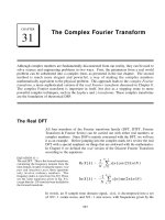
Figure 1-1. Example of a structural description.
productions where they are not directly relevant to the context. For this
reason, the full syntax is included in AppendixA, and should be consulted
as a reference.
1.1. Describing Structure
A digital electronic system can be described as a module with inputs
and/or outputs. The electrical values on the outputs are some function of
the values on the inputs. Figure1-1(a) shows an example of this view of a
digital system. The module
F has two inputs, A and B, and an output Y.
Using VHDL terminology, we call the module
F a design entity, and the
inputs and outputs are called ports.
One way of describing the function of a module is to describe how it is
composed of sub-modules. Each of the sub-modules is an instance of some
entity, and the ports of the instances are connected using signals.
Figure1-1(b) shows how the entity
F might be composed of instances of
entities
G, H and I. This kind of description is called a structural
description. Note that each of the entities
G, H and I might also have a
structural description.
1.2. Describing Behaviour
In many cases, it is not appropriate to describe a module structurally.
One such case is a module which is at the bottom of the hierarchy of some
other structural description. For example, if you are designing a system
using IC packages bought from an IC shop, you do not need to describe the
internal structure of an IC. In such cases, a description of the function
performed by the module is required, without reference to its actual
internal structure. Such a description is called a functional or behavioural
description.
To illustrate this, suppose that the function of the entity
F in
Figure1-1(a) is the exclusive-or function. Then a behavioural description of
F could be the Boolean function
Y = A . B + A . B
More complex behaviours cannot be described purely as a function of
inputs. In systems with feedback, the outputs are also a function of time.
VHDL solves this problem by allowing description of behaviour in the form
1.
Introduction 1-3
of an executable program. Chapters2 and4 describe the programming
language facilities.
1.3. Discrete Event Time Model
Once the structure and behaviour of a module have been specified, it is
possible to simulate the module by executing its bevioural description. This
is done by simulating the passage of time in discrete steps. At some
simulation time, a module input may be stimulated by changing the value
on an input port. The module reacts by running the code of its behavioural
description and scheduling new values to be placed on the signals
connected to its output ports at some later simulated time. This is called
scheduling a transaction on that signal. If the new value is different from
the previous value on the signal, an event occurs, and other modules with
input ports connected to the signal may be activated.
The simulation starts with an initialisation phase, and then proceeds by
repeating a two-stage simulation cycle. In the initialisation phase, all
signals are given initial values, the simulation time is set to zero, and each
module’s behaviour program is executed. This usually results in
transactions being scheduled on output signals for some later time.
In the first stage of a simulation cycle, the simulated time is advanced to
the earliest time at which a transaction has been scheduled. All
transactions scheduled for that time are executed, and this may cause
events to occur on some signals.
In the second stage, all modules which react to events occurring in the
first stage have their behaviour program executed. These programs will
usually schedule further transactions on their output signals. When all of
the behaviour programs have finished executing, the simulation cycle
repeats. If there are no more scheduled transactions, the whole simulation
is completed.
The purpose of the simulation is to gather information about the
changes in system state over time. This can be done by running the
simulation under the control of a simulation monitor. The monitor allows
signals and other state information to be viewed or stored in a trace file for
later analysis. It may also allow interactive stepping of the simulation
process, much like an interactive program debugger.
1.4. A Quick Example
In this section we will look at a small example of a VHDL description of
a two-bit counter to give you a feel for the language and how it is used. We
start the description of an entity by specifying its external interface, which
includes a description of its ports. So the counter might be defined as:
entity count2 is
generic (prop_delay : Time := 10 ns);
port (clock : in bit;
q1, q0 : out bit);
end count2;
This specifies that the entity count2 has one input and two outputs, all of
which are bit values, that is, they can take on the values '0' or '1'. It also
defines a generic constant called
prop_delay which can be used to control the
operation of the entity (in this case its propagation delay). If no value is
1-4 The VHDL Cookbook
T_FLIPFLOP
CK Q
INVERTER
AY
T_FLIPFLOP
CK Q
COUNT2
CLOCK Q
0
Q1
FF1
FF0
INV_FF0
BIT_0
BIT_1
INV
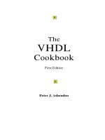
Figure1-2. Structure of count2.
explicitly given for this value when the entity is used in a design, the default
value of 10ns will be used.
An implementation of the entity is described in an architecture body.
There may be more than one architecture body corresponding to a single
entity specification, each of which describes a different view of the entity.
For example, a behavioural description of the counter could be written as:
architecture behaviour of count2 is
begin
count_up: process (clock)
variable count_value : natural := 0;
begin
if clock = '1' then
count_value := (count_value + 1) mod 4;
q0 <= bit'val(count_value mod 2) after prop_delay;
q1 <= bit'val(count_value / 2) after prop_delay;
end if;
end process count_up;
end behaviour;
In this description of the counter, the behaviour is implemented by a
process called
count_up, which is sensitive to the input clock. A process is a
body of code which is executed whenever any of the signals it is sensitive to
changes value. This process has a variable called
count_value to store the
current state of the counter. The variable is initialized to zero at the start of
simulation, and retains its value between activations of the process. When
the
clock input changes from '0' to '1', the state variable is incremented, and
transactions are scheduled on the two output ports based on the new value.
The assignments use the generic constant
prop_delay to determine how long
after the clock change the transaction should be scheduled. When control
reaches the end of the process body, the process is suspended until another
change occurs on
clock.
The two-bit counter might also be described as a circuit composed of two
T-flip-flops and an inverter, as shown in Figure1-2. This can be written in
VHDL as:
1.
Introduction 1-5
architecture structure of count2 is
component t_flipflop
port (ck : in bit; q : out bit);
end component;
component inverter
port (a : in bit; y : out bit);
end component;
signal ff0, ff1, inv_ff0 : bit;
begin
bit_0 : t_flipflop port map (ck => clock, q => ff0);
inv : inverter port map (a => ff0, y => inv_ff0);
bit_1 : t_flipflop port map (ck => inv_ff0, q => ff1);
q0 <= ff0;
q1 <= ff1;
end structure;
In this architecture, two component types are declared, t_flipflop and
inverter, and three internal signals are declared. Each of the components is
then instantiated, and the ports of the instances are mapped onto signals
and ports of the entity. For example,
bit_0 is an instance of the t_flipflop
component, with its ck port connected to the clock port of the count2 entity,
and its
q port connected to the internal signal ff0. The last two signal
assignments update the entity ports whenever the values on the internal
signals change.
2-1
2. VHDL is Like a Programming Language
As mentioned in Section 1.2, the behaviour of a module may be described
in programming language form. This chapter describes the facilities in
VHDL which are drawn from the familiar programming language
repertoire. If you are familiar with the Ada programming language, you
will notice the similarity with that language. This is both a convenience
and a nuisance. The convenience is that you don’t have much to learn to
use these VHDL facilities. The problem is that the facilities are not as
comprehensive as those of Ada, though they are certainly adequate for most
modeling purposes.
2.1. Lexical Elements
2.1.1. Comments
Comments in VHDL start with two adjacent hyphens (‘ ’) and extend to
the end of the line. They have no part in the meaning of a VHDL
description.
2.1.2. Identifiers
Identifiers in VHDL are used as reserved words and as programmer
defined names. They must conform to the rule:
identifier ::= letter { [ underline ] letter_or_digit }
Note that case of letters is not considered significant, so the identifiers cat
and Cat are the same. Underline characters in identifiers are significant,
so
This_Name and ThisName are different identifiers.
2.1.3. Numbers
Literal numbers may be expressed either in decimal or in a base
between two and sixteen. If the literal includes a point, it represents a real
number, otherwise it represents an integer. Decimal literals are defined
by:
decimal_literal ::= integer [ . integer ] [ exponent ]
integer ::= digit { [ underline ] digit }
exponent ::= E [ + ] integer | E - integer
Some examples are:
0 1 123_456_789 987E6 integer literals
0.0 0.5 2.718_28 12.4E-9 real literals
Based literal numbers are defined by:
based_literal ::= base # based_integer [ . based_integer ] # [ exponent ]
base ::= integer
based_integer ::= extended_digit { [ underline ] extended_digit }
2-2 The VHDL Cookbook
extended_digit ::= digit | letter
The base and the exponent are expressed in decimal. The exponent
indicates the power of the base by which the literal is multiplied. The
letters A to F (upper or lower case) are used as extended digits to represent
10 to 15. Some examples:
2#1100_0100# 16#C4# 4#301#E1 the integer 196
2#1.1111_1111_111#E+11 16#F.FF#E2 the real number 4095.0
2.1.4. Characters
Literal characters are formed by enclosing an ASCII character in
single-quote marks. For example:
'A' '*' ''' ' '
2.1.5. Strings
Literal strings of characters are formed by enclosing the characters in
double-quote marks. To include a double-quote mark itself in a string, a
pair of double-quote marks must be put together. A string can be used as a
value for an object which is an array of characters. Examples of strings:
"A string"
"" empty string
"A string in a string: ""A string"". " contains quote marks
2.1.6. Bit Strings
VHDL provides a convenient way of specifying literal values for arrays of
type
bit ('0's and '1's, see Section 2.2.5). The syntax is:
bit_string_literal ::= base_specifier " bit_value "
base_specifier ::= B | O | X
bit_value ::= extended_digit { [ underline ] extended_digit }
Base specifier B stands for binary, O for octal and X for hexadecimal. Some
examples:
B"1010110" length is 7
O"126" length is 9, equivalent to B"001_010_110"
X"56" length is 8, equivalent to B"0101_0110"
2.2. Data Types and Objects
VHDL provides a number of basic, or scalar, types, and a means of
forming composite types. The scalar types include numbers, physical
quantities, and enumerations (including enumerations of characters), and
there are a number of standard predefined basic types. The composite types
provided are arrays and records. VHDL also provides access types
(pointers) and files, although these will not be fully described in this booklet.
A data type can be defined by a type declaration:
full_type_declaration ::= type identifier is type_definition ;
type_definition ::=
scalar_type_definition
| composite_type_definition
| access_type_definition
| file_type_definition
scalar_type_definition ::=
enumeration_type_definition | integer_type_definition
| floating_type_definition | physical_type_definition
2.
VHDL is Like a Programming Language 2-3
composite_type_definition ::=
array_type_definition
| record_type_definition
Examples of different kinds of type declarations are given in the following
sections.
2.2.1. Integer Types
An integer type is a range of integer values within a specified range.
The syntax for specifying integer types is:
integer_type_definition ::= range_constraint
range_constraint ::= range range
range ::= simple_expression direction simple_expression
direction ::= to | downto
The expressions that specify the range must of course evaluate to integer
numbers. Types declared with the keyword
to are called ascending ranges,
and those declared with the keyword
downto are called descending ranges.
The VHDL standard allows an implementation to restrict the range, but
requires that it must at least allow the range –2147483647 to +2147483647.
Some examples of integer type declarations:
type byte_int is range 0 to 255;
type signed_word_int is range –32768 to 32767;
type bit_index is range 31 downto 0;
There is a predefined integer type called integer. The range of this type is
implementation defined, though it is guaranteed to include –2147483647 to
+2147483647.
2.2.2. Physical Types
A physical type is a numeric type for representing some physical
quantity, such as mass, length, time or voltage. The declaration of a
physical type includes the specification of a base unit, and possibly a
number of secondary units, being multiples of the base unit. The syntax for
declaring physical types is:
physical_type_definition ::=
range_constraint
units
base_unit_declaration
{ secondary_unit_declaration }
end units
base_unit_declaration ::= identifier ;
secondary_unit_declaration ::= identifier = physical_literal ;
physical_literal ::= [ abstract_literal ] unit_name
Some examples of physical type declarations:
2-4 The VHDL Cookbook
type length is range 0 to 1E9
units
um;
mm = 1000 um;
cm = 10 mm;
m = 1000 mm;
in = 25.4 mm;
ft = 12 in;
yd = 3 ft;
rod = 198 in;
chain = 22 yd;
furlong = 10 chain;
end units;
type resistance is range 0 to 1E8
units
ohms;
kohms = 1000 ohms;
Mohms = 1E6 ohms;
end units;
The predefined physical type time is important in VHDL, as it is used
extensively to specify delays in simulations. Its definition is:
type time is range
implementation_defined
units
fs;
ps = 1000 fs;
ns = 1000 ps;
us = 1000 ns;
ms = 1000 us;
sec = 1000 ms;
min = 60 sec;
hr = 60 min;
end units;
To write a value of some physical type, you write the number followed by
the unit. For example:
10 mm 1 rod 1200 ohm 23 ns
2.2.3. Floating Point Types
A floating point type is a discrete approximation to the set of real
numbers in a specified range. The precision of the approximation is not
defined by the VHDL language standard, but must be at least six decimal
digits. The range must include at least –1E38 to +1E38. A floating point
type is declared using the syntax:
floating_type_definition := range_constraint
Some examples are:
type signal_level is range –10.00 to +10.00;
type probability is range 0.0 to 1.0;
There is a predefined floating point type called real. The range of this
type is implementation defined, though it is guaranteed to include –1E38 to
+1E38.
2.2.4. Enumeration Types
An enumeration type is an ordered set of identifiers or characters. The
identifiers and characters within a single enumeration type must be
distinct, however they may be reused in several different enumeration
types.
2.
VHDL is Like a Programming Language 2-5
The syntax for declaring an enumeration type is:
enumeration_type_definition ::= ( enumeration_literal { , enumeration_literal } )
enumeration_literal ::= identifier | character_literal
Some examples are:
type logic_level is (unknown, low, undriven, high);
type alu_function is (disable, pass, add, subtract, multiply, divide);
type octal_digit is ('0', '1', '2', '3', '4', '5', '6', '7');
There are a number of predefined enumeration types, defined as follows:
type severity_level is (note, warning, error, failure);
type boolean is (false, true);
type bit is ('0', '1');
type character is (
NUL, SOH, STX, ETX, EOT, ENQ, ACK, BEL,
BS, HT, LF, VT, FF, CR, SO, SI,
DLE, DC1, DC2, DC3, DC4, NAK, SYN, ETB,
CAN, EM, SUB, ESC, FSP, GSP, RSP, USP,
' ', '!', '"', '#', '$', '%', '&', ''',
'(', ')', '*', '+', ',', '-', '.', '/',
'0', '1', '2', '3', '4', '5', '6', '7',
'8', '9', ':', ';', '<', '=', '>', '?',
'@', 'A', 'B', 'C', 'D', 'E', 'F', 'G',
'H', 'I', 'J', 'K', 'L', 'M', 'N', 'O',
'P', 'Q', 'R', 'S', 'T', 'U', 'V', 'W',
'X', 'Y', 'Z', '[', '\', ']', '^', '_',
'`', 'a', 'b', 'c', 'd', 'e', 'f', 'g',
'h', 'i', 'j', 'k', 'l', 'm', 'n', 'o',
'p', 'q', 'r', 's', 't', 'u', 'v', 'w',
'x', 'y', 'z', '{', '|', '}', '~', DEL);
Note that type character is an example of an enumeration type containing a
mixture of identifiers and characters. Also, the characters '0' and '1' are
members of both
bit and character . Where '0' or '1' occur in a program, the
context will be used to determine which type is being used.
2.2.5. Arrays
An array in VHDL is an indexed collection of elements all of the same
type. Arrays may be one-dimensional (with one index) or multi-
dimensional (with a number of indices). In addition, an array type may be
constrained, in which the bounds for an index are established when the
type is defined, or unconstrained, in which the bounds are established
subsequently.
The syntax for declaring an array type is:
array_type_definition ::=
unconstrained_array_definition | constrained_array_definition
unconstrained_array_definition ::=
array ( index_subtype_definition { , index_subtype_definition } )
of element_subtype_indication
constrained_array_definition ::=
array index_constraint of element_subtype_indication
index_subtype_definition ::= type_mark range <>
index_constraint ::= ( discrete_range { , discrete_range } )
discrete_range ::= discrete_subtype_indication | range
2-6 The VHDL Cookbook
Subtypes, referred to in this syntax specification, will be discussed in detail
in Section2.2.7.
Some examples of constrained array type declarations:
type word is array (31 downto 0) of bit;
type memory is array (address) of word;
type transform is array (1 to 4, 1 to 4) of real;
type register_bank is array (byte range 0 to 132) of integer;
An example of an unconstrained array type declaration:
type vector is array (integer range <>) of real;
The symbol ‘<>’ (called a box) can be thought of as a place-holder for the
index range, which will be filled in later when the array type is used. For
example, an object might be declared to be a vector of 20 elements by giving
its type as:
vector(1 to 20)
There are two predefined array types, both of which are unconstrained.
They are defined as:
type string is array (positive range <>) of character;
type bit_vector is array (natural range <>) of bit;
The types positive and natural are subtypes of integer, defined in Section2.2.7
below. The type
bit_vector is particularly useful in modeling binary coded
representations of values in simulations of digital systems.
An element of an array object can referred to by indexing the name of
the object. For example, suppose
a and b are one- and two-dimensional
array objects respectively. Then the indexed names
a(1) and b(1, 1) refer to
elements of these arrays. Furthermore, a contiguous slice of a one-
dimensional array can be referred to by using a range as an index. For
example
a(8 to 15) is an eight-element array which is part of the array a.
Sometimes you may need to write a literal value of an array type. This
can be done using an array aggregate, which is a list of element values.
Suppose we have an array type declared as:
type a is array (1 to 4) of character;
and we want to write a value of this type containing the elements 'f', 'o', 'o',
'd' in that order. We could write an aggregate with positional association
as follows:
('f', 'o', 'o', 'd')
in which the elements are listed in the order of the index range, starting
with the left bound of the range. Alternatively, we could write an aggregate
with named association:
(1 => 'f', 3 => 'o', 4 => 'd', 2 => 'o')
In this case, the index for each element is explicitly given, so the elements
can be in any order. Positional and named association can be mixed within
an aggregate, provided all the positional associations come first. Also, the
word
others can be used in place of an index in a named association,
indicating a value to be used for all elements not explicitly mentioned. For
example, the same value as above could be written as:
('f', 4 => 'd', others => 'o')
2.
VHDL is Like a Programming Language 2-7
2.2.6. Records
VHDL provides basic facilities for records, which are collections of
named elements of possibly different types. The syntax for declaring record
types is:
record_type_definition ::=
record
element_declaration
{ element_declaration }
end record
element_declaration ::= identifier_list : element_subtype_definition ;
identifier_list ::= identifier { , identifier )
element_subtype_definition ::= subtype_indication
An example record type declaration:
type instruction is
record
op_code : processor_op;
address_mode : mode;
operand1, operand2: integer range 0 to 15;
end record;
When you need to refer to a field of a record object, you use a selected
name. For example, suppose that
r is a record object containing a field
called
f. Then the name r.f refers to that field.
As for arrays, aggregates can be used to write literal values for records.
Both positional and named association can be used, and the same rules
apply, with record field names being used in place of array index names.
2.2.7. Subtypes
The use of a subtype allows the values taken on by an object to be
restricted or constrained subset of some base type. The syntax for declaring
a subtype is:
subtype_declaration ::= subtype identifier is subtype_indication ;
subtype_indication ::= [ resolution_function_name ] type_mark [ constraint ]
type_mark ::= type_name | subtype_name
constraint ::= range_constraint | index_constraint
There are two cases of subtypes. Firstly a subtype may constrain values
from a scalar type to be within a specified range (a range constraint). For
example:
subtype pin_count is integer range 0 to 400;
subtype digits is character range '0' to '9';
Secondly, a subtype may constrain an otherwise unconstrained array
type by specifying bounds for the indices. For example:
subtype id is string(1 to 20);
subtype word is bit_vector(31 downto 0);
There are two predefined numeric subtypes, defined as:
subtype natural is integer range 0 to
highest_integer
subtype positive is integer range 1 to
highest_integer
2-8 The VHDL Cookbook
2.2.8. Object Declarations
An object is a named item in a VHDL description which has a value of a
specified type. There are three classes of objects: constants, variables and
signals. Only the first two will be discusses in this section; signals will be
covered in Section3.2.1. Declaration and use of constants and variables is
very much like their use in programming languages.
A constant is an object which is initialised to a specified value when it is
created, and which may not be subsequently modified. The syntax of a
constant declaration is:
constant_declaration ::=
constant identifier_list : subtype_indication [ := expression ] ;
Constant declarations with the initialising expression missing are called
deferred constants, and may only appear in package declarations (see
Section2.5.3). The initial value must be given in the corresponding package
body. Some examples:
constant e : real := 2.71828;
constant delay : Time := 5 ns;
constant max_size : natural;
A variable is an object whose value may be changed after it is created.
The syntax for declaring variables is:
variable_declaration ::=
variable identifier_list : subtype_indication [ := expression ] ;
The initial value expression, if present, is evaluated and assigned to the
variable when it is created. If the expression is absent, a default value is
assigned when the variable is created. The default value for scalar types is
the leftmost value for the type, that is the first in the list of an enumeration
type, the lowest in an ascending range, or the highest in a descending
range. If the variable is a composite type, the default value is the
composition of the default values for each element, based on the element
types.
Some examples of variable declarations:
variable count : natural := 0;
variable trace : trace_array;
Assuming the type trace_array is an array of boolean, then the initial value of
the variable
trace is an array with all elements having the value false.
Given an existing object, it is possible to give an alternate name to the
object or part of it. This is done using and alias declaration. The syntax is:
alias_declaration ::= alias identifier : subtype_indication is name ;
A reference to an alias is interpreted as a reference to the object or part
corresponding to the alias. For example:
variable instr : bit_vector(31 downto 0);
alias op_code : bit_vector(7 downto 0) is instr(31 downto 24);
declares the name op_code to be an alias for the left-most eight bits of instr.
2.2.9. Attributes
Types and objects declared in a VHDL description can have additional
information, called attributes, associated with them. There are a number
of standard pre-defined attributes, and some of those for types and arrays
2.
VHDL is Like a Programming Language 2-9
are discussed here. An attribute is referenced using the ‘'’ notation. For
example,
thing'attr
refers to the attribute attr of the type or object thing.
Firstly, for any scalar type or subtype T, the following attributes can be
used:
Attribute Result
T'left Left bound of T
T'right Right bound of T
T'low Lower bound of T
T'high Upper bound of T
For an ascending range, T'left = T'low, and T'right = T'high. For a
descending range, T'left = T'high, and T'right = T'low.
Secondly, for any discrete or physical type or subtype T, X a member of T,
and N an integer, the following attributes can be used:
Attribute Result
T'pos(X) Position number of X in T
T'val(N) Value at position N in T
T'leftof(X) Value in T which is one position left from X
T'rightof(X) Value in T which is one position right from X
T'pred(X) Value in T which is one position lower than X
T'succ(X) Value in T which is one position higher than X
For an ascending range, T'leftof(X) = T'pred(X), and T'rightof(X) =
T'succ(X). For a descending range, T'leftof(X) = T'succ(X), and T'rightof(X)
= T'pred(X).
Thirdly, for any array type or object A, and N an integer between 1 and
the number of dimensions of A, the following attributes can be used:
Attribute Result
A'left(N) Left bound of index range of dim’n N of A
A'right(N) Right bound of index range of dim’n N of A
A'low(N) Lower bound of index range of dim’n N of A
A'high(N) Upper bound of index range of dim’n N of A
A'range(N) Index range of dim’n N of A
A'reverse_range(N) Reverse of index range of dim’n N of A
A'length(N) Length of index range of dim’n N of A
2.3. Expressions and Operators
Expressions in VHDL are much like expressions in other programming
languages. An expression is a formula combining primaries with
operators. Primaries include names of objects, literals, function calls and
parenthesized expressions. Operators are listed in Table 2-1 in order of
decreasing precedence.
The logical operators
and, or, nand, nor, xor and not operate on values of
type
bit or boolean, and also on one-dimensional arrays of these types. For
array operands, the operation is applied between corresponding elements of
each array, yielding an array of the same length as the result. For
bit and
2-10 The VHDL Cookbook
Highest precedence: **
abs not
*/
mod rem
+ (sign) – (sign)
+–&
=/=<<=>>=
Lowest precedence:
and or nand nor xor
Table 7-1. Operators and precedence.
boolean operands, and, or, nand, and nor are ‘short-circuit’ operators, that
is they only evaluate their right operand if the left operand does not
determine the result. So
and and nand only evaluate the right operand if
the left operand is true or '1', and
or and nor only evaluate the right
operand if the left operand is false or '0'.
The relational operators =, /=, <, <=, > and >= must have both operands
of the same type, and yield
boolean results. The equality operators (= and /=)
can have operands of any type. For composite types, two values are equal if
all of their corresponding elements are equal. The remaining operators
must have operands which are scalar types or one-dimensional arrays of
discrete types.
The sign operators (+ and –) and the addition (+) and subtraction (–)
operators have their usual meaning on numeric operands. The
concatenation operator (&) operates on one-dimensional arrays to form a
new array with the contents of the right operand following the contents of
the left operand. It can also concatenate a single new element to an array,
or two individual elements to form an array. The concatenation operator is
most commonly used with strings.
The multiplication (*) and division (/) operators work on integer, floating
point and physical types types. The modulus (
mod) and remainder (rem)
operators only work on integer types. The absolute value (
abs) operator
works on any numeric type. Finally, the exponentiation (**) operator can
have an integer or floating point left operand, but must have an integer
right operand. A negative right operand is only allowed if the left operand
is a floating point number.
2.4. Sequential Statements
VHDL contains a number of facilities for modifying the state of objects
and controlling the flow of execution of models. These are discussed in this
section.
2.4.1. Variable Assignment
As in other programming languages, a variable is given a new value
using an assignment statement. The syntax is:
variable_assignment_statement ::= target := expression ;
target ::= name | aggregate
In the simplest case, the target of the assignment is an object name, and
the value of the expression is given to the named object. The object and the
value must have the same base type.
2.
VHDL is Like a Programming Language 2-11
If the target of the assignment is an aggregate, then the elements listed
must be object names, and the value of the expression must be a composite
value of the same type as the aggregate. Firstly, all the names in the
aggregate are evaluated, then the expression is evaluated, and lastly the
components of the expression value are assigned to the named variables.
This is effectively a parallel assignment. For example, if a variable
r is a
record with two fields
a and b, then they could be exchanged by writing
(a => r.b, b => r.a) := r
(Note that this is an example to illustrate how such an assignment works;
it is not an example of good programming practice!)
2.4.2. If Statement
The if statement allows selection of statements to execute depending on
one or more conditions. The syntax is:
if_statement ::=
if condition then
sequence_of_statements
{ elsif condition then
sequence_of_statements }
[ else
sequence_of_statements ]
end if ;
The conditions are expressions resulting in boolean values. The
conditions are evaluated successively until one found that yields the value
true. In that case the corresponding statement list is executed. Otherwise,
if the else clause is present, its statement list is executed.
2.4.3. Case Statement
The case statement allows selection of statements to execute depending
on the value of a selection expression. The syntax is:
case_statement ::=
case expression is
case_statement_alternative
{ case_statement_alternative }
end case ;
case_statement_alternative ::=
when choices =>
sequence_of_statements
choices ::= choice { | choice }
choice ::=
simple_expression
| discrete_range
| element_simple_name
| others
The selection expression must result in either a discrete type, or a one-
dimensional array of characters. The alternative whose choice list
includes the value of the expression is selected and the statement list
executed. Note that all the choices must be distinct, that is, no value may be
duplicated. Furthermore, all values must be represented in the choice
lists, or the special choice
others must be included as the last alternative. If
no choice list includes the value of the expression, the others alternative is
selected. If the expression results in an array, then the choices may be
strings or bit strings.
2-12 The VHDL Cookbook
Some examples of case statements:
case element_colour of
when red =>
statements for red
;
when green | blue =>
statements for green or blue
;
when orange to turquoise =>
statements for these colours
;
end case;
case opcode of
when X"00" => perform_add;
when X"01" => perform_subtract;
when others => signal_illegal_opcode;
end case;
2.4.4. Loop Statements
VHDL has a basic loop statement, which can be augmented to form the
usual while and for loops seen in other programming languages. The
syntax of the loop statement is:
loop_statement ::=
[ loop_label : ]
[ iteration_scheme ] loop
sequence_of_statements
end loop [ loop_label ] ;
iteration_scheme ::=
while condition
| for loop_parameter_specification
parameter_specification ::=
identifier in discrete_range
If the iteration scheme is omitted, we get a loop which will repeat the
enclosed statements indefinitely. An example of such a basic loop is:
loop
do_something;
end loop;
The while iteration scheme allows a test condition to be evaluated before
each iteration. The iteration only proceeds if the test evaluates to true. If
the test is false, the loop statement terminates. An example:
while index < length and str(index) /= ' ' loop
index := index + 1;
end loop;
The for iteration scheme allows a specified number of iterations. The
loop parameter specification declares an object which takes on successive
values from the given range for each iteration of the loop. Within the
statements enclosed in the loop, the object is treated as a constant, and so
may not be assigned to. The object does not exist beyond execution of the
loop statement. An example:
for item in 1 to last_item loop
table(item) := 0;
end loop;
There are two additional statements which can be used inside a loop to
modify the basic pattern of iteration. The ‘next’ statement terminates
execution of the current iteration and starts the subsequent iteration. The
2.
VHDL is Like a Programming Language 2-13
‘exit’ statement terminates execution of the current iteration and
terminates the loop. The syntax of these statements is:
next_statement ::= next [ loop_label ] [ when condition ] ;
exit_statement ::= exit [ loop_label ] [ when condition ] ;
If the loop label is omitted, the statement applies to the inner-most
enclosing loop, otherwise it applies to the named loop. If the when clause is
present but the condition is false, the iteration continues normally. Some
examples:
for i in 1 to max_str_len loop
a(i) := buf(i);
exit when buf(i) = NUL;
end loop;
outer_loop : loop
inner_loop : loop
do_something;
next outer_loop when temp = 0;
do_something_else;
end loop inner_loop;
end loop outer_loop;
2.4.5. Null Statement
The null statement has no effect. It may be used to explicitly show that
no action is required in certain cases. It is most often used in case
statements, where all possible values of the selection expression must be
listed as choices, but for some choices no action is required. For example:
case controller_command is
when forward => engage_motor_forward;
when reverse => engage_motor_reverse;
when idle => null;
end case;
2.4.6. Assertions
An assertion statement is used to verify a specified condition and to
report if the condition is violated. The syntax is:
assertion_statement ::=
assert condition
[ report expression ]
[ severity expression ] ;
If the report clause is present, the result of the expression must be a string.
This is a message which will be reported if the condition is false. If it is
omitted, the default message is "Assertion violation". If the severity clause
is present the expression must be of the type
severity_level. If it is omitted,
the default is
error. A simulator may terminate execution if an assertion
violation occurs and the severity value is greater than some
implementation dependent threshold. Usually the threshold will be under
user control.
2.5. Subprograms and Packages
Like other programming languages, VHDL provides subprogram
facilities in the form of procedures and functions. VHDL also provided a
package facility for collecting declarations and objects into modular units.
Packages also provide a measure of data abstraction and information
hiding.
2-14 The VHDL Cookbook
2.5.1. Procedures and Functions
Procedure and function subprograms are declared using the syntax:
subprogram_declaration ::= subprogram_specification ;
subprogram_specification ::=
procedure designator [ ( formal_parameter_list ) ]
| function designator [ ( formal_parameter_list ) ] return type_mark
A subprogram declaration in this form simply names the subprogram and
specifies the parameters required. The body of statements defining the
behaviour of the subprogram is deferred. For function subprograms, the
declaration also specifies the type of the result returned when the function
is called. This form of subprogram declaration is typically used in package
specifications (see Section 2.5.3), where the subprogram body is given in the
package body, or to define mutually recursive procedures.
The syntax for specifying the formal parameters of a subprogram is:
formal_parameter_list ::= parameter_interface_list
interface_list ::= interface_element { ; interface_element }
interface_element ::= interface_declaration
interface_declaration ::=
interface_constant_declaration
| interface_signal_declaration
| interface_variable_declaration
interface_constant_declaration ::=
[ constant ] identifier_list : [ in ] subtype_indication [ := static_expression ]
interface_variable_declaration ::=
[ variable ] identifier_list : [ mode ] subtype_indication [ := static_expression ]
For now we will only consider constant and variable parameters, although
signals can also be used(see Chapter3). Some examples will clarify this
syntax. Firstly, a simple example of a procedure with no parameters:
procedure reset;
This simply defines reset as a procedure with no parameters, whose
statement body will be given subsequently in the VHDL program. A
procedure call to
reset would be:
reset;
Secondly, here is a declaration of a procedure with some parameters:
procedure increment_reg(variable reg : inout word_32;
constant incr : in integer := 1);
In this example, the procedure increment_reg has two parameters, the
first called
reg and the second called incr. Reg is a variable parameter,
which means that in the subprogram body, it is treated as a variable object
and may be assigned to. This means that when the procedure is called, the
actual parameter associated with
reg must itself be a variable. The mode of
reg is inout, which means that reg can be both read and assigned to. Other
possible modes for subprogram parameters are
in, which means that the
parameter may only be read, and
out, which means that the parameter
may only be assigned to. If the mode is
inout or out, then the word variable
can be omitted and is assumed.
The second parameter,
incr, is a constant parameter, which means that
it is treated as a constant object in the subprogram statement body, and may
not be assigned to. The actual parameter associated with
incr when the
procedure is called must be an expression. Given the mode of the