The MPEG Representation of Digital Media potx
Bạn đang xem bản rút gọn của tài liệu. Xem và tải ngay bản đầy đủ của tài liệu tại đây (3.95 MB, 275 trang )
The MPEG Representation of Digital Media
Leonardo Chiariglione
Editor
The MPEG Representation
of Digital Media
Editor
Leonardo Chiariglione
CEDEO
Via Borgionera 103
10040 Villar Dora, Italy
ISBN 978-1-4419-6183-9 e-ISBN 978-1-4419-6184-6
DOI 10.1007/978-1-4419-6184-6
Springer New York Dordrecht Heidelberg London
Library of Congress Control Number: 2011936224
© Springer Science+Business Media, LLC 2012
All rights reserved. This work may not be translated or copied in whole or in part without the written
permission of the publisher (Springer Science+Business Media, LLC, 233 Spring Street, New York,
NY 10013, USA), except for brief excerpts in connection with reviews or scholarly analysis. Use in
connection with any form of information storage and retrieval, electronic adaptation, computer software,
or by similar or dissimilar methodology now known or hereafter developed is forbidden.
The use in this publication of trade names, trademarks, service marks, and similar terms, even if they
are not identifi ed as such, is not to be taken as an expression of opinion as to whether or not they are
subject to proprietary rights.
Printed on acid-free paper
Springer is part of Springer Science+Business Media (www.springer.com)
v
Contents
1 An Introduction to MPEG Digital Media 1
Leonardo Chiariglione
2 MPEG Video Compression Basics 7
B.G. Haskell and A. Puri
3 MPEG Video Compression Advances 39
Jens-Rainer Ohm and Gary J. Sullivan
4 MPEG Video Compression Future 69
Jörn Ostermann and Masayuki Tanimoto
5 MPEG Image and Video Signature 81
Miroslaw Z. Bober and Stavros Paschalakis
6 MPEG Audio Compression Basics 97
Marina Bosi
7 MPEG Audio Compression Advances 125
Schuyler Quackenbush
8 MPEG Audio Compression Future 141
Schuyler Quackenbush
9 MPEG System Basics 161
Peter P. Schirling
10 MPEG Multimedia Scene Representation 177
Young-Kwon Lim, Cyril Concolato, Jean Le Feuvre,
and Kyuheon Kim
vi
Contents
11 MPEG 3D Graphics Representation 203
Francisco Morán Burgos and Marius Preda
12 MPEG Reconfi gurable Video Representation 231
Marco Mattavelli
13 MPEG Video/Audio Quality Evaluation 249
Vittorio Baroncini and Schuyler Quackenbush
Abbreviated List of Acronyms 263
1
L. Chiariglione (ed.), The MPEG Representation of Digital Media,
DOI 10.1007/978-1-4419-6184-6_1, © Springer Science+Business Media, LLC 2012
The Moving Picture Experts Group (MPEG) has produced a number of successful
standards that have facilitated the conversion of the various components of the
media industry from an analogue to the digital world. In the process MPEG has
caused an orderly restructuring of the industry from a largely vertical arrangement
to a horizontal one. This has been possible thanks to a properly designed standards
development process that accommodates industry practices and promotes a healthy
technology competition.
A communication system requires the means to convert a message to a form that
is suitable for transmission over the selected channel. In a verbal communication
acoustic waves are the channel and modulation of the waves in accordance to the
intended verbal message is the means to convert the message to a form suitable for
transmission over the channel. The channel used by sound recording of the early
days was a medium (vinyl disc) that could be graved in proportion to the intensity
of the sound and the means to convert the message was a membrane that converted
sound intensity to the movement of a stylus. Analogue facsimile used a telephone
line as the channel and a sensor detecting the intensity of the light from a page as
the means to modulate the intensity of the telephone signal.
In the 170 years since the development of photography, the first media commu-
nication system that could communicate media information without human inter-
vention, a very large number of such systems have been invented and deployed.
As it is clear from the examples above, while the message can be considered as an
abstract entity independent of the communication system, the means to convert the
message to a form suitable for transmission over a selected channel is in general
specific of that channel.
L. Chiariglione (*)
CEDEO.net, Via Borgionera 103, 10040 Villar Dora, Turin, Italy
e-mail:
Chapter 1
An Introduction to MPEG Digital Media
Leonardo Chiariglione
2
L. Chiariglione
The use of channels based on electrical, magnetic and electromagnetic techniques
has made simpler the definition of a more generic form of “information representa-
tion” for communication. In the example above the microphone output can in
principle be used for recording, transmission over a cable or over a radio channel.
In general, however, the wildly differing specificities of the transmission mecha-
nism have led designers of such communication systems to produce independent,
“vertical” systems that are not able to communicate between them.
The development of digital technologies has triggered the birth of a new branch
of science called Digital Signal Processing (DSP). Once electrical, magnetic, elec-
tromagnetic and even mechanical signals carrying information are converted into
numbers, it is possible to convert the abstract entity called “message” into a digital
form that is still “abstract” – because it does not depend on the channel – and can be
processed by, stored in and communicated to physical devices for eventual conver-
sion to a form that can be perceived by human senses.
Because of the designers’ tendency to produce “vertical” solutions, analogue
communication systems used to be beset with interoperability problems – suffice it
to recall the incompatibilities between Beta and VHS video recorders or between
the many colour television systems, the many versions of NTSC, PAL and SECAM.
The existence of a digital representation of information could have led designers to
produce more “horizontal” solutions, but the first digital communication systems
designed, and some of them deployed, in the 1980s were still following the old
pattern.
MPEG was established in 1988 in the framework of the International Organisation
for Standardisation (ISO). The main driver for its creation was to exploit standardi-
sation as the means to create markets for products and services with improved user
experience because of assured interoperability. More than 20 years after that, one
can indeed assess that MPEG standards for the digital representation of audio, video
and related information have facilitated the transition of the media industry to the
digital world, made convergence of hitherto disparate industries less chaotic than it
could have been and sustains the growth of the industry at large.
Mindful of the need to create a layered organisation as opposed to the existing
vertical organisation, MPEG has consistently applied its notion of “digital represen-
tation of information” to provide standard solutions that are, to the extent possible,
independent of specific applications and industries. As a result its standards are
indeed used by the broadest range of communication industries ever achieved in
history and have been the drivers of the fastest ever transformation of an industry
from a set of vertical systems to a set of horizontal layers.
This has been achieved by amalgamating industry practices into a set of coher-
ent practices proper of the MPEG group. The typical process of MPEG standard
development goes through the phases of gathering and rationalisation of require-
ments from multi-industry sources; the issuing of “Calls for proposals” of tech-
nologies or solutions satisfying some or all requirements; testing of and selection
among suitable proposals; integration of proposed technologies into a complete
solution; several rounds of ballots in the ISO National Bodies to perfect the solu-
tion; development of reference software, a complete implementation of the encoder
3
1 An Introduction to MPEG Digital Media
(i.e. the part of the communication system that generates the digital representation
of information) and of the decoder (i.e. the part that generates the information from
its digital representation); development of conformance testing methodology to
assess conformance of an implementation to the standard; verification testing to
verify the degree of satisfaction of the standard to the original requirements; release
of the agreed standard.
The process described requires that MPEG standards be anticipatory, in the sense
that standards are developed anticipating needs that are not yet entirely defined.
Obviously MPEG takes a risk but this is unavoidable if a standard technology is
to be available before members of the industry make commitments to some other
technology before a standard exists.
MPEG implements the ISO/IEC-defined standard development process in a very
meticulous way, even adding some further steps. A typical MPEG standard goes
through the phases of project identification, requirements definition, call for pro-
posals, assessment of proposals, development of test model, working draft, com-
mittee draft, final committee draft, final draft international standard, verification
test, conformance test. Therefore, when all steps are required and complex tech-
nologies are involved, it may take some time for MPEG to develop a standard.
Still the process is very healthy because it fosters competition among its members,
but actually not just members since the rule in MPEG is that anybody is entitled to
respond to a call for proposals (but membership is required to participate in the
development of the standard). Letting companies compete with their technologies at
the time a standard is being developed is very effective because competition happens
at the time of important technology choices – those impacting on the performance
of the standard – but also less wasteful because competition does not require the
actual deployment of products or services that typically require investments orders
of magnitude larger than those required by standardisation.
Since its early days, MPEG has discovered that targeting its standards to satisfy the
needs of a broad range of industries is an obviously laudable but often nearly impos-
sible task to achieve. Indeed requirements may be too diverse: an industry may seek
maximum performance, another low cost and yet another flexibility. All this bearing
in mind that convergence – an easy word for a complex phenomenon – may force
different parts of different industries to coalesce.
MPEG has found a solution to this problem with the adoption of Profiles and
Levels. With Profiles MPEG is able to control the amount of “technology” (i.e.
features, performance and sometimes complexity) needed in an instance of the stan-
dard and with Levels MPEG is able to control the amount of “resources” (e.g. video
resolution) involved.
Another feature of MPEG standards is the provision – whenever possible – of
integrated solutions. MPEG prides itself for having been the first to develop a com-
plete “system-level” standard solution for digital audio and video. The MPEG-1
standard includes a part for “video compression”, another for “audio compression”
and a third for “putting the two digital streams together” so that an application can
deal with an “audio-visual” stream. This practice was followed with MPEG-2,
MPEG-4 and MPEG-7 and is likely to continue for some of the planned standard.
4
L. Chiariglione
MPEG was one of the first bodies to make intense use of programming languages
in the actual design of its standards to the extent of writing significant parts of its
standards in a pseudo C code. Therefore it was easy to make the further step of
providing, next to its traditional textual form, computer code implementing a stan-
dard. In later standards the computer code has been given “normative” status, in the
sense that “human readable” text and “machine readable” computer code are two
alternative representations of the same standard.
Going against the practice of other bodies, MPEG has consistently applied the
notion that standards should specify the minimum that is required for interopera-
bility between implementations of transmitters (encoders) and receivers (decoders)
from different sources. Therefore all MPEG standards contain clauses with norma-
tive value for decoders while the corresponding text for encoders has only informa-
tive value. The unique advantage of this policy is that there is a great deal of freedom
in the design of encoders whose “performance” can improve over time partly as a
result of the implementation of new ideas and partly from the continuous improve-
ment of technology that enables more sophisticated implementations.
As MPEG standards are very sophisticated and offer a lot of freedom to the
designer, sometimes incompatibilities between encoders and decoders from differ-
ent sources arise. Continuing the established tradition of some industries (e.g. tele-
com, broadcasting and consumer electronics) all MPEG standards contain
“conformance testing” clauses and suites to help implementors assess the confor-
mity of their products to a standard before releasing them to the market.
Many MPEG standards carry the result of many years of research by companies
participating in their development. Therefore MPEG is well aware that those who
have invested in new successful technologies typically expect to be rewarded of
their efforts that enable standards to provide leading-edge performance. MPEG
develops its standards in accordance to the ISO/IEC/ITU Intellectual Property
Rights (IPR) rules having as sole guidance the production of the most effective
standards, with due regard to the state of technology.
As a body seeking to serve the needs of different industries across the board,
MPEG sees it difficult and often improper to establish relationships with individual
companies. On the other hand MPEG is fully aware that industries have felt and
keep on feeling the need to establish organisations catering to their needs. MPEG
has ongoing “liaison” relationships with some 50 organisations, within ISO, with
the other two international standards organisations International Electrotechnical
Commission (IEC) and International Telecommunication Union (ITU), and with a
host of other bodies.
Of particular importance is the relationship with Study Group 16 (SG 16) of ITU.
Since the time of the MPEG-2 Systems and Video standards (ISO/IEC 13818-1 and -2)
MPEG has seen the benefit for the industry to exploit multi-industry standards
jointly developed under the auspices of the international standardisation organisa-
tions – ISO, IEC and ITU – to serve the needs of their constituencies. This collabora-
tion was resumed in 2001 with the goal of producing a new generation video coding
standard – ISO/IEC 14496-10 Advanced Video Coding (AVC) and is currently
progressing with the High-Efficiency Video Coding (HEVC) standard project.
5
1 An Introduction to MPEG Digital Media
Judging from the title of its mission “digital representation of media information”,
the scope of MPEG may seem narrow. In practice, however, the scope is hardly so.
Probably the area drawing most participants is “media compression”, which includes
video, audio, 3D graphics (3DG) and other media types. A second area is “media
composition”, namely the digital representation of “attributes” (time, space, interac-
tivity, etc.) of the different “objects” in a multimedia scene. A third area is “media
description”, namely the digital representation of the description – textual, but other
descriptions as well – related to a media object. MPEG has several other activity
areas that will not be described in this book. For sure the MPEG mission is highly
strategic, judging from the some 500 participants in its quarterly meetings repre-
senting some 200 companies and organisations from some 25 countries.
After this introduction the book continues with three chapters dealing with past,
present and future of MPEG video coding standards. Chapter 5 provides some sam-
ples of the huge world of MPEG “media description” standards focusing on video.
The next three chapters deal with past, present and future of MPEG audio coding
standards. Chapters 9 and 10 describe the task of “putting together” digital media for
two types of MPEG standards. Chapter 11 introduces the world of standards for com-
pression of 3DG information and is followed by Chap. 12 dealing with a new future-
oriented approach to video and 3DG information coding. Chapter 13 deals with
“subjective testing” of audio and video information that is used by MPEG throughout
its entire process of video and audio coding standard development.
This book seeks to provide to its readers the means to achieve a basic technology
understanding of the mechanisms underpinning the operation of MPEG standards
for those making decisions in products and services based on digital media, those
engaged in studies or developments of MPEG-related implementations starting
from general background and those curious about such a wonderful developer of
successful standard technologies as MPEG.
7
L. Chiariglione (ed.), The MPEG Representation of Digital Media,
DOI 10.1007/978-1-4419-6184-6_2, © Springer Science+Business Media, LLC 2012
2.1 Video Coding Basics
Video signals differ from image signals in several important characteristics. Of
course the most important difference is that video signals have a camera frame rate
of anywhere from 15 to 60 frames/s, which provides the illusion of smooth motion
in the displayed signal.
1
Another difference between images and video is the ability
to exploit temporal redundancy as well as spatial redundancy in designing compres-
sion methods for video. For example, we can take advantage of the fact that objects
in video sequences tend to move in predictable patterns, and can therefore be
motion-compensated from frame-to-frame if we can detect the object and its motion
trajectory over time.
Historically, there have been five major initiatives in video coding [1–5] that
have led to a range of video standards.
Video coding for ISDN video teleconferencing, which has led to the ITU video s
coding standard called H.261 [6]. H.261 is also the baseline video mode for most
multimedia conferencing systems.
Video coding for low bitrate video telephony over POTSs
2
networks with as little
as 10 kbits/s allocated to video and as little as 5.3 kbits/s allocated to voice
coding, which led to the ITU video coding standard called H.263 [7]. The H.263
low bitrate video codec is used at modem rates of from 14.4 to 56 kbits/s, where
the modem rate includes video coding, speech coding, control information, and
other logical channels for data.
B.G. Haskell (*)
Apple Computer, 1 Infinite Loop, Cupertino, CA 95014, USA
e-mail:
Chapter 2
MPEG Video Compression Basics
B.G. Haskell and A. Puri
1
If the camera rate, chosen to portray motion, is below the display rate, chosen to avoid flicker,
then some camera frames will have to be repeated.
2
Plain Old Telephone Service.
8
B.G. Haskell and A. Puri
Video coding for storing movies on CD-ROM with on the order of 1.2 Mbits/s s
allocated to video coding and 256 kbits/s allocated to audio coding, which led to
the initial ISO MPEG-1 (Motion Picture Experts Group) standard [8].
Video coding for broadband ISDN, broadcast and for storing video on DVD s
(Digital Video Disks) with on the order of 2–400 Mbits/s allocated to video and
audio coding, which led to the ISO MPEG-2 video coding standard [9]. The ITU
has given this standard the number H.262.
Video coding for s object-based coding at rates as low as 8 kbits/s, and as high as
1 Mbits/s, or higher, which led to the ISO MPEG-4 video coding standard [10].
Key aspects of this standard include independent coding of objects in a picture; the
ability to interactively composite these objects into a scene at the display; the abil-
ity to combine graphics, animated objects, and natural objects in the scene; and
finally the ability to transmit scenes in higher dimensionality formats (e.g., 3D).
Before delving in to details of standards, a few general remarks are in order. It is
important to note that standards specify syntax and semantics of the compressed bit
stream produced by the video encoder, and how this bit stream is to be parsed and
decoded (i.e., decoding procedure) to produce a decompressed video signal. However,
many algorithms and parameter choices in the encoding are not specified (such as
motion estimation, selection of coding modes, allocation of bits to different parts of
the picture, etc.) and are left open and depend greatly on encoder implementation.
However it is a requirement that resulting bit stream from encoding be compliant to
the specified syntax. The result is that the quality of standards based video codecs,
even at a given bitrate, depends greatly on the encoder implementation. This explains
why some implementations appear to yield better video quality than others.
In the following sections, we provide brief summaries of each of these video
standards, with the goal of describing the basic coding algorithms as well as the
features that support use of the video coding in multimedia applications.
2.1.1 Basics of Interframe Video Coding
A video scene captured as a sequence of frames can be efficiently coded by
estimating and compensating for motion between frames prior to generating inter-
frame difference signal for coding. Since motion compensation is a key element in
most video coders, it is worthwhile understanding the basic concepts in this pro-
cessing step.
For the ease of processing, each frame of video is uniformly partitioned into
smaller units called Macroblocks (MBs, formally defined a bit later) where each
macroblock consists of a 16 × 16 block of luma, and corresponding chroma blocks.
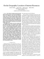
The way that the motion estimator works is illustrated in Fig. 2.1. Each block of
pixels (say 16 × 16 luma block of a MB) in the current frame is compared with a set
of candidate blocks of same size in the previous frame to determine the one that best
predicts the current block. The set of blocks includes those within a search region in
previous frame centered on the position of current block in the current frame.
9
2 MPEG Video Compression Basics
When the best matching block is found, a motion vector is determined, which
specifies the reference block.
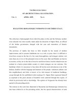
Figure
2.2 shows a block diagram of a motion-compensated image codec. The
key idea is to combine transform coding (in the form of the Discrete Cosine
Transform (DCT) of 8 × 8 pixel blocks) with predictive coding (in the form of
mv
current
frame
previous
frame
A’
A
Fig. 2.1 Motion compensation of interframe blocks
Quant.
Inv. 2D
DCT
Inv.
Quant.
Motion
Estimator
Motion Compe-
nsated Predictor
Variable
Length
Encoder
2D
DCT
Buffer
Variable
Length
Decoder
MOTION
VECTORS
Inv.
Quant.
Inv. 2D
DCT
Motion Compe-
nsated Predictor
Buffer
$%#/$%2
%.#/$%2
MOTION
VECTORS
Fig. 2.2 Motion compensated encoder/decoder for interframe coding
10
B.G. Haskell and A. Puri
differential Pulse Code Modulation (PCM)) in order to reduce storage and
computation of the compressed image, and at the same time to give a high degree of
compression and adaptability.
Since motion compensation is difficult to perform in the transform domain, the
first step in the interframe coder is to create a motion compensated prediction error
in the pixel domain. For each block of current frame, a prediction block in the refer-
ence frame is found using motion vector found during motion estimation, and dif-
ferenced to generate prediction error signal. This computation requires only a single
frame store in the encoder and decoder. The resulting error signal is transformed
using 2D DCT, quantized by an adaptive quantizer, entropy encoded using a Variable
Length Coder (VLC) and buffered for transmission over a fixed rate channel.
We now discuss how various MPEG standards are built using principles and
building blocks discussed so far.
2.2 The MPEG-1 Video Coding Standard
The MPEG-1 standard is the first true multimedia standard with specifications for
coding, compression, and transmission of audio, video, and data streams in a series
of synchronized, mixed Packets. The driving focus of the standard was storage of
multimedia content on a standard CDROM, which supported data transfer rates of
1.4 Mb/s and a total storage capability of about 600 MB. MPEG-1 was intended to
provide VHS VCR-like video and audio quality, along with VCR-like controls.
MPEG-1 is formally called ISO/IEC 11172.
2.2.1 Requirements of the MPEG-1 Video Standard
Uncompressed digital video of full component TV resolution requires a very high
transmission bandwidth, while VHS VCR-grade equivalent raw digital video
requires transmission bandwidth of around 30 Mbits/s, with compression still nec-
essary to reduce the bit-rate to suit most applications. The required degree of com-
pression is achieved by exploiting the spatial and temporal redundancy present in a
video signal. However, the compression process is inherently lossy, and the signal
reconstructed from the compressed bit stream is not identical to the input video
signal. Compression typically introduces some artifacts into the decoded signal.
The primary requirement of the MPEG-1 video standard was that it should achieve
the high quality of the decoded motion video at a given bit-rate. In addition to picture
quality under normal play conditions, different applications have additional requirements.
For instance, multimedia applications may require the ability to randomly access and
decode any single video picture
3
in the bitstream. Also, the ability to perform fast
3
Frames and pictures are synonymous in MPEG-1.
11
2 MPEG Video Compression Basics
search directly on the bit stream, both forward and backward, is extremely desirable
if the storage medium has “seek” capabilities. It is also useful to be able to edit com-
pressed bit streams directly while maintaining decodability. And finally, a variety of
video formats were needed to be supported.
2.2.2 H.261 Coding Concepts as Applicable to MPEG-1 Video
The H.261 standard employs interframe video coding that was described earlier.
H.261 codes video frames using a DCT on blocks of size 8 × 8 pixels, much the same
as used for the original JPEG coder for still images. An initial frame (called an INTRA
frame) is coded and transmitted as an independent frame. Subsequent frames, which
are modeled as changing slowly due to small motions of objects in the scene, are
coded efficiently in the INTER mode using a technique called Motion Compensation
(MC) in which the displacement of groups of pixels from their position in the previous
frame (as represented by so-called motion vectors) are transmitted together with the
DCT coded difference between the predicted and original images.
2.2.2.1 H.261 Bitstream Data Hierarchy
We will first explain briefly the data structure in an H.261 video bit stream and then
the functional elements in an H.261 decoder.
Only two picture formats, common intermediate format (CIF) and quarter-CIF
(QCIF), are allowed. CIF pictures are made of three components: luminance Y and
color differences Cb and Cr, as defined in ITU-R Recommendation BT601. The CIF
picture size for Y is 352 pels
4
per line by 288 lines per frame. The two color differ-
ence signals are subsampled to 176 pels per line and 144 lines per frame. The image
aspect ratio is 4(horizontal):3(vertical), and the picture rate is 29.97 non-interlaced
frames per second. All H.261 standard codecs must be able to operate with QCIF;
CIF is optional. A picture frame is partitioned into 8 line × 8 pel image blocks.
A Macroblock (MB) is defined as four 8 × 8 (or one 16 × 16) Y block/s, one Cb
block, and one Cr block at the same location.
The compressed H.261 video bit stream contains several layers. They are picture
layer, group of blocks (GOB) layer, Macroblock (MB) layer, and block layer. The
higher layer consists of its own header followed by a number of lower layers.
Picture Layer
In a compressed video bit stream, we start with the picture layer. Its header contains:
Picture start code (PSC) a 20-bit pattern.
4
Abbreviation of pixel.
12
B.G. Haskell and A. Puri
Temporal reference (TR) a 5-bit input frame number.
Type information (PTYPE) such as CIF/QCIF selection.
Spare bits to be defined in later versions.
GOB Layer
At the GOB layer, a GOB header contains:
Group of blocks start code (GBSC) a 16-bit pattern.s
Group number (GN) a 4-bit GOB address.s
Quantizer information (GQUANT) initial quantizer step size normalized to the s
range 1–31. At the start of a GOB, we set QUANT = GQUANT.
Spare bits to be defined in later versions of the standard.s
Next, comes the MB layer. An 11-bit stuffing pattern can be inserted repetitively
right after a GOB header or after a transmitted Macroblock.
Macroblock (MB) Layer
At the MB layer, the header contains:
Macroblock address (MBA) location of this MB relative to the previously coded s
MB inside the GOB. MBA equals one plus the number of skipped MBs preceding
the current MB in the GOB.
Type information (MTYPE) 10 types in total.s
Quantizer (MQUANT) normalized quantizer step size to be used until the next s
MQUANT or GQUANT. If MQUANT is received we set QUANT = MQUANT.
Range is 1–31.
Motion vector data (MVD) differential displacement vector.s
Coded block pattern (CBP) indicates which blocks in the MB are coded.s
Blocks not coded are assumed to contain all zero coefficients.
Block Layer
The lowest layer is the block layer, consisting of quantized transform coefficients
(TCOEFF), followed by the end of block (EOB) symbol. All coded blocks have the
EOB symbol.
Not all header information need be present. For example, at the MB layer, if an
MB is not Inter motion-compensated (as indicated by MTYPE), MVD does not
exist. Also, MQUANT is optional. Most of the header information is coded using
Variable Length Codewords.
There are essentially four types of coded MBs as indicated by MTYPE:
Intra – original pels are transform-coded.s
Inter – frame difference pels (with zero-motion vectors) are coded. Skipped MBs s
are considered inter by default.
13
2 MPEG Video Compression Basics
Inter_MC – displaced (nonzero-motion vectors) frame differences are coded.s
Inter_MC_with_filter – the displaced blocks are filtered by a predefined loop s
filter, which may help reduce visible coding artifacts at very low bit rates.
2.2.2.2 H.261 Coding Semantics
A single-motion vector (horizontal and vertical displacement) is transmitted for one
Inter_MC MB. That is, the four Y blocks, one Cb, and one Cr block all share the
same motion vector. The range of motion vectors is +− 15 Y pels with integer values.
For color blocks, the motion vector is obtained by halving the transmitted vector
and truncating the magnitude to an integer value.
Motion vectors are differentially coded using, in most cases, the motion vector of
the MB to the left as a prediction. Zero is used as a prediction for the leftmost MBs
of the GOB, and also if the MB to the left has no motion vector.
The transform coefficients of either the original (Intra) or the differential (Inter)
pels are ordered according to a zigzag scanning pattern. These transform coefficients
are selected and quantized at the encoder, and then coded using variable-length code-
words (VLCs) and/or fixed-length codewords (FLC), depending on the values. Just
as with JPEG, successive zeros between two nonzero coefficients are counted and
called a RUN. The value of a transmitted nonzero quantized coefficient is called a
LEVEL. The most likely occurring combinations of (RUN, LEVEL) are encoded
with a VLC, with the sign bit terminating the RUN-LEVEL VLC codeword.
The standard requires a compatible IDCT (inverse DCT) to be close to the ideal
64-bit floating point IDCT. H.261 specifies a measuring process for checking a valid
IDCT. The error in pel values between the ideal IDCT and the IDCT under test must
be less than certain allowable limits given in the standard, e.g., peak error <= 1,
mean error <= 0.0015, and mean square error <= 0.02.
A few other items are also required by the standard. One of them is the image-block
updating rate. To prevent mismatched IDCT error as well as channel error propagation,
every MB should be intra-coded at least once in every 132 transmitted picture frames.
The contents of the transmitted video bit stream must also meet the requirements
of the hypothetical reference decoder (HRD). For CIF pictures, every coded frame
is limited to fewer than 256 Kbits; for QCIF, the limit is 64 Kbits, where K = 1,024.
The HRD receiving buffer size is B + 256 Kbits, where B = 4 × R
max
/29.97 and R
max
is the maximum connection (channel) rate. At every picture interval (1/29.97 s), the
HRD buffer is examined. If at least one complete coded picture is in the buffer, then
the earliest picture bits are removed from the buffer and decoded. The buffer occu-
pancy, right after the above bits have been removed, must be less than B.
2.2.3 MPEG-1 Video Coding
Video coding as per MPEG-1 uses coding concepts similar to H.261 just described,
namely spatial coding by taking the DCT of 8 × 8 pixel blocks, quantizing the DCT
14
B.G. Haskell and A. Puri
coefficients based on perceptual weighting criteria, storing the DCT coefficients for
each block in a zigzag scan, and doing a variable run length coding of the resulting
DCT coefficient stream. Temporal coding is achieved by using the ideas of uni- and
bi- directional motion compensated prediction, with three types of pictures resulting,
namely:
s I or Intra pictures which were coded independently of all previous or future
pictures.
s P or Predictive pictures which were coded based on previous I or previous P
pictures.
s B or Bi-directionally predictive pictures which were coded based on either the
next and/or the previous pictures.
If video is coded at about 1.1 Mbits/s and stereo audio is coded at 128 kbits/s per
channel, then the total audio/video digital signal will fit onto the CD-ROM bit-rate
of approximately 1.4 Mbits/s as well as the North American ISDN Primary Rate
(23 B-channels) of 1.47 Mbits/s. The specified bit-rate of 1.5 Mbits/s is not a hard
upper limit. In fact, MPEG-1 allows rates as high as 100 Mbits/s. However, during
the course of MPEG-1 algorithm development, coded image quality was optimized
at a rate of 1.1 Mbits/s using progressive (NonInterlaced) scanned pictures.
Two Source Input Formats (SIF) were used for optimization. One corresponding
to NTSC was 352 pels, 240 lines, 29.97 frames/s. The other corresponding to PAL,
was 352 pels, 288 lines, 25 frames/s. SIF uses 2:1 color subsampling, both horizon-
tally and vertically, in the same 4:2:0 format as H.261.
2.2.3.1 Basics of MPEG-1 Video Compression
Both spatial and temporal redundancy reduction are needed for the high compression
requirements of MPEG-1. Most techniques used by MPEG-1 have been described
earlier.
Exploiting Spatial Redundancy
The compression approach of MPEG-1 video combines elements of JPEG, ele-
ments of H.261, and significant new elements that allow not only higher compres-
sion but also frequent entry points into the video stream.
Because video is a sequence of still images, it is possible to achieve some com-
pression using techniques similar to JPEG. Such methods of compression are called
intraframe coding techniques, where each picture of video is individually and inde-
pendently compressed or encoded. Intraframe coding exploits the spatial redun-
dancy that exists between adjacent pels of a picture. Pictures coded using only
intraframe coding are called I-pictures.
As in JPEG and H.261, the MPEG-1 video-coding algorithm employs a block-
based two-dimensional DCT. A picture is first divided into 8 × 8 blocks of pels, and the
two-dimensional DCT is then applied independently on each block. This operation
15
2 MPEG Video Compression Basics
results in an 8 × 8 block of DCT coefficients in which most of the energy in the original
(pel) block is typically concentrated in a few low-frequency coefficients. The coeffi-
cients are scanned and transmitted in the same zigzag order as JPEG and H.261.
A quantizer is applied to the DCT coefficients, which sets many of them to zero.
This quantization is responsible for the lossy nature of the compression algorithms
in JPEG, H.261 and MPEG-1 video. Compression is achieved by transmitting only
the coefficients that survive the quantization operation and by entropy-coding their
locations and amplitudes.
Exploiting Temporal Redundancy
Many of the interactive requirements can be satisfied by intraframe coding. However,
as in H.261, the quality achieved by intraframe coding alone is not sufficient for
typical video signals at bit-rates around 1.1 Mbits/s.
Temporal redundancy results from a high degree of correlation between adjacent
pictures. The MPEG-1 algorithm exploits this redundancy by computing an
interframe difference signal called the prediction error. In computing the prediction
error, the technique of motion compensation is employed to correct for motion.
A Macroblock (MB) approach is adopted for motion compensation.
In unidirectional or Forward Prediction, 16 × 16 luma block of each macroblock
in the current picture to be coded is matched with a block of the same size in a
previous picture called the Reference picture. As in H.261 blocks of the Reference
picture that “best match” the 16 × 16 luma blocks of current picture, are called the
Prediction blocks. The prediction error is then computed as the difference between
the Target block and the Prediction block.
5
The position of this best-matching
Prediction block is indicated by a motion vector that describes the displacement
between it and the Target block. Unlike H.261 where each motion vector is specified
at “integer pel” accuracy, in MPEG-1 each motion vector is specified at “half-pel”
accuracy, thus allowing improved prediction. The motion vector information is also
encoded and transmitted along with the prediction error. Pictures coded using
Forward Prediction are called P-pictures.
The prediction error itself is transmitted using the DCT-based intraframe
encoding technique summarized above. In MPEG-1 video (as in H.261), motion
compensation is performed on MBs (16 × 16 luma and associated chroma), repre-
senting a reasonable trade-off between the compression provided by motion com-
pensation and the cost associated with transmitting the motion vectors.
Bidirectional Temporal Prediction
Bidirectional temporal prediction, also called Motion-Compensated Interpolation,
is a key feature of MPEG-1 video. Pictures coded with Bidirectional prediction use
5
Prediction 16 × 16 blocks do not, in general, align with coded 16 × 16 luma (of MB) boundaries in
the Reference frame.
16
B.G. Haskell and A. Puri
two Reference pictures, one in the past and one in the future. A Target 16 × 16 luma
block in bidirectionally coded pictures can be predicted by a 16 × 16 block from the
past Reference picture (Forward Prediction), or one from the future Reference
picture (Backward Prediction), or by an average of two 16 × 16 luma blocks,
one from each Reference picture (Interpolation). In every case, a Prediction 16 × 16
block from a Reference picture is associated with a motion vector, so that up to two
motion vectors per macroblock may be used with Bidirectional prediction. As in the
case of unidirectional prediction, motion vectors are represented at “half-pel” accu-
racy. Motion-Compensated Interpolation for a 16 × 16 block in a Bidirectionally
predicted “current” frame is illustrated in Fig. 2.3.
Pictures coded using Bidirectional Prediction are called B-pictures. Pictures that
are Bidirectionally predicted are never themselves used as Reference pictures, i.e.,
Reference pictures for B-pictures must be either P-pictures or I-pictures. Similarly,
Reference pictures for P-pictures must also be either P-pictures or I-pictures.
Bidirectional prediction provides a number of advantages. The primary one is
that the compression obtained is typically higher than can be obtained from Forward
(unidirectional) prediction alone. To obtain the same picture quality, Bidirectionally
predicted pictures can be encoded with fewer bits than pictures using only Forward
prediction.
However, Bidirectional prediction does introduce extra delay in the encoding
process, because pictures must be encoded out of sequence. Further, it entails extra
encoding complexity because block matching (the most computationally intensive
encoding procedure) has to be performed twice for each Target block, once with the
past Reference picture and once with the future Reference picture.
2.2.3.2 MPEG-1 Bitstream Data Hierarchy
The MPEG-1 video standard specifies the syntax and semantics of the compressed
bit stream produced by the video encoder. The standard also specifies how this bit
stream is to be parsed and decoded to produce a decompressed video signal.
current
frame
previous
frame
future
frame
mv
f
A
’
b
A
mv
b
A
’
f
Fig. 2.3 Motion compensated interpolation in a bidirectionally predicted picture
17
2 MPEG Video Compression Basics
The details of the motion estimation matching procedure are not part of the
standard. However, as with H.261 there is a strong limitation on the variation in bits/
picture in the case of constant bit-rate operation. This is enforced through a Video
Buffer Verifier (VBV), which corresponds to the Hypothetical Reference Decoder
of H.261. Any MPEG-1 bit stream is prohibited from overflowing or underflowing
the buffer of this VBV. Thus, unlike H.261, there is no picture skipping allowed in
MPEG-1.
The bit-stream syntax is flexible in order to support the variety of applications
envisaged for the MPEG-1 video standard. To this end, the overall syntax is con-
structed in a hierarchy
6
of several Headers, each performing a different logical
function.
Video Sequence Header
The outermost Header is called the Video Sequence Header, which contains basic
parameters such as the size of the video pictures, Pel Aspect Ratio (PAR), picture
rate, bit-rate, assumed VBV buffer size and certain other global parameters. This
Header also allows for the optional transmission of JPEG style Quantizer Matrices,
one for Intra coded pictures and one for Non-Intra coded pictures. Unlike JPEG, if
one or both quantizer matrices are not sent, default values are defined. Private user
data can also be sent in the Sequence Header as long as it does not contain a Start
Code Header, which MPEG-1 defines as a string of 23 or more zeros.
Group of Pictures (GOP) Header
Below the Video Sequence Header is the Group of Pictures (GOP) Header, which
provides support for random access, fast search, and editing. A sequence of trans-
mitted video pictures is divided into a series of GOPs, where each GOP contains an
intra-coded picture (I-picture) followed by an arrangement of Forward predictive-
coded pictures (P-pictures) and Bidirectionally predicted pictures (B-pictures).
Figure
2.4 shows a GOP example with six pictures, 1–6. This GOP contains
I-picture 1, P-pictures 4 and 6, and B-pictures 2, 3 and 5. The encoding/transmission
order of the pictures in this GOP is shown at the bottom of Fig. 2.4. B-pictures 2 and 3
are encoded after P-picture 4, using P-picture 4 and I-picture 1 as reference. Note that
B-picture 7 in Fig. 2.4 is part of the next GOP because it is encoded after I-picture 8.
Random access and fast search are enabled by the availability of the I-pictures,
which can be decoded independently and serve as starting points for further
decoding . The MPEG-1 video standard allows GOPs to be of arbitrary structure and
length.
6
As in H.261, MPEG-1 uses the term Layers for this hierarchy. However, Layer has another
meaning in MPEG-2. Thus, to avoid confusion we will not use Layers in this section.
18
B.G. Haskell and A. Puri
Picture Header
Below the GOP is the Picture Header, which contains the type of picture that is
present, e.g., I, P or B, as well as a Temporal Reference indicating the position of
the picture in display order within the GOP. It also contains a parameter called
vbv_delay that indicates how long to wait after a random access before starting to
decode. Without this information, a decoder buffer could underflow or overflow
following a random access.
Slice Header
A Slice is a string of consecutive Macroblocks of arbitrary length running from left
to right and top to bottom across the picture. The Slice Header is intended to be used
for re-synchronization in the event of transmission bit errors. Prediction registers
used in the differential encoding of motion vectors and DC Intra coefficients are
reset at the start of a Slice. It is again the responsibility of the encoder to choose the
length of each Slice depending on the expected bit error conditions. The first and
last MBs of a Slice cannot be skipped MBs, and gaps are not allowed between
Slices. The Slice Header contains the vertical position of the Slice within the picture,
as well as a quantizer_scale parameter (corresponding to GQUANT in H.261).
Macroblock Header
The Macroblock (MB) is the 16 × 16 motion compensation unit. In the Macroblock
Header, the horizontal position (in MBs) of the first MB of each Slice is coded with
the MB Address VLC. The positions of additional transmitted MBs are coded
12 3 4 5 6 8
14
23 6 587
Display order
Encoding order
I
B
P
B
P
B
I
B
7
Fig. 2.4 Illustration of motion compensated coding of frames