SIEMENS - simatic programming with step 7 v5.3 doc
Bạn đang xem bản rút gọn của tài liệu. Xem và tải ngay bản đầy đủ của tài liệu tại đây (3.29 MB, 570 trang )
s
Preface, Contents
Introducing the Product and Installing
the Software
1
Installation 2
Working Out the
Automation Concept
3
Basics of Designing a
Program Structure
4
Startup and Operation 5
Setting Up and Editing the Project 6
Editing Projects with different Versions
of STEP 7
7
Defining Symbols 8
Creating Blocks and Libraries 9
Creating Logic Blocks 10
Creating Data Blocks 11
Parameter Assignment
for Data Blocks
12
Creating STL Source Files 13
Displaying Reference Data 14
Checking Block Consistency and Time
Stamps as a Block Property
15
Configuring Messages 16
Controlling and Monitoring Variables 17
Establishing an Online Connection and
Making CPU Settings
18
Downloading and Uploading 19
Debugging 20
Testing Using Program Status 21
Testing using the Simulation Program
(Optional Package)
22
Diagnostics 23
Printing and Archiving 24
Working with M7 Programmable
Control Systems
25
Tips and Tricks 26
Appendix A
Index
SIMATIC
Programming with
STEP 7 V5.3
Manual
This manual is part of the documentation
package with the order number:
6ES7810-4CA07-8BW0
Edition 01/2004
A5E00261405-01
Copyright © Siemens AG 2004 All rights reserved
The reproduction, transmission or use of this document or its
contents is not permitted without express written authority.
Offenders will be liable for damages. All rights, including rights
created by patent grant or registration of a utility model or design,
are reserved.
Siemens AG
Bereich Automation and Drives
Geschaeftsgebiet Industrial Automation Systems
Postfach 4848, D- 90327 Nuernberg
Disclaimer of Liability
We have checked the contents of this manual for agreement with
the hardware and software described. Sin
ce deviations cannot be
precluded entirely, we cannot guarantee full agreement. However,
the data in this manual are reviewed regularly and any necessary
corrections included in subsequent editions. Suggestions for
improvement are welcomed.
©Siemens AG 2004
Technical data subject to change.
Siemens Aktiengesellschaft A5E00261405-01
Safety Guidelines
This manual contains notices intended to ensure personal safety, as well as to protect the products and
connected equipment against damage. These notices are highlighted by the symbols shown below and
graded according to severity by the following texts:
!
Danger
indicates that death, severe personal injury or substantial property damage will result if proper
precautions are not taken.
!
Warning
indicates that death, severe personal injury or substantial property damage can result if proper
precautions are not taken.
!
Caution
indicates that minor personal injury can result if proper precautions are not taken.
Caution
indicates that property damage can result if proper precautions are not taken.
Notice
draws your attention to particularly important information on the product, handling the product, or to a
particular part of the documentation.
Qualified Personnel
Only qualified personnel should be allowed to install and work on this equipment. Qualified persons
are defined as persons who are authorized to commission, to ground and to tag circuits, equipment, and
systems in accordance with established safety practices and standards.
Correct Usage
Note the following:
!
Warning
This device and its components may only be used for the applications described in the catalog or the
technical description, and only in connection with devices or components from other manufacturers
which have been approved or recommended by Siemens.
This product can only function correctly and safely if it is transported, stored, set up, and installed
correctly, and operated and maintained as recommended.
Trademarks
SIMATIC®, SIMATIC HMI® and SIMATIC NET® are registered trademarks of SIEMENS AG.
Third parties using for their own purposes any other names in this document which refer to trademarks
might infringe upon the rights of the trademark owners.
Programming with STEP 7 V5.3
A5E00261405-01
iii
Preface
Purpose
This manual provides a complete overview of programming with STEP 7. It is
designed to support you when installing and commissioning the software. It
explains how to proceed when creating programs and describes the components of
user programs.
The manual is intended for people who are involved in carrying out control tasks
using STEP 7 and SIMATIC S7 automation systems.
We recommend that you familiarize yourself with the examples in the manual
"Working with STEP 7 V5.3, Getting Started." These examples provide an easy
introduction to the topic "Programming with STEP 7."
Basic Knowledge Required
In order to understand this manual, general knowledge of automation technology is
required.
In addition, you must be familiar with using computers or PC-similar tools (for
example, programming devices) with the MS Windows 2000 Professional or
MS Windows XP Professional operating system.
Scope of the Manual
This manual is valid for release 5.3 of the STEP 7 programming software package.
You can find the latest information on the service packs:
• in the "readme.wri" file
• in the updated STEP 7 online help.
The topic "What's new?" in the online help offers an excellent introduction and
overview of the newest STEP 7 innovations.
Preface
Programming with STEP 7 V5.3
iv A5E00261405-01
STEP 7 Documentation Packages
This manual is part of the documentation package "STEP 7 Basic Information.“
The following table displays an overview of the STEP 7 documentation:
Documentation Purpose Order Number
STEP 7 Basic Information with
• Working with STEP 7 V5.3,
Getting Started Manual
• Programming with STEP 7 V5.3
• Configuring Hardware and
Communication Connections,
STEP 7 V5.3
• From S5 to S7, Converter Manual
Basic information for technical
personnel describing the methods
of implementing control tasks with
STEP 7 and the S7-300/400
programmable controllers.
6ES7810-4CA07-8BW0
STEP 7 Reference with
• Ladder Logic (LAD)/Function Block
Diagram (FBD)/Statement List (STL)
for S7-300/400 manuals
• Standard and System Functions for
S7-300/400
Provides reference information
and describes the programming
languages LAD, FBD, and STL,
and standard and system
functions extending the scope of
the STEP 7 basic information.
6ES7810-4CA07-8BW1
Online Helps Purpose Order Number
Help on STEP 7 Basic information on
programming and configuring with
STEP 7 in the form of an online
help.
Part of the STEP 7
Standard software.
Reference helps on STL/LAD/FBD
Reference help on SFBs/SFCs
Reference help on Organization Blocks
Context-sensitive reference
information.
Part of the STEP 7
Standard software.
Preface
Programming with STEP 7 V5.3
A5E00261405-01
v
Online Help
The manual is complemented by an online help which is integrated in the software.
This online help is intended to provide you with detailed support when using the
software.
The help system is integrated in the software via a number of interfaces:
• There are several menu commands which you can select in the Help menu: The
Contents command opens the index for the Help on Step 7.
• Using Help provides detailed instructions on using the online help.
• The context-sensitive help offers information on the current context, for example, an
open dialog box or an active window. You can open the context-sensitive help by
clicking the "Help" button or by pressing F1.
• The status bar offers another form of context-sensitive help. It displays a short
explanation for each menu command when the mouse pointer is positioned on the menu
command.
• A brief explanation is also displayed for each icon in the toolbar when the mouse
pointer is positioned on the icon for a short time.
If you prefer to read the information from the online help in printed format, you can
print out individual help topics, books, or the entire online help.
This manual, as well as the manuals "Configuring Hardware with STEP 7",
"Modifiying the System During Operation via CiR" and "Automation System
S7 400H - Fault-tolerant Systems" is an extract from the HTML-based Help on
STEP 7. For detailed procedures please refer to the STEP 7 help. As the manuals
and the online help share an almost identical structure, it is easy to switch between
the manuals and the online help.
You can find the electronic manuals after installing STEP 7 via the Windows Start
menu: Start > SIMATIC > Documentation.
Further Support
If you have any technical questions, please get in touch with your Siemens
representative or agent responsible.
You will find your contact person at:
/>
Training Centers
Siemens offers a number of training courses to introduce you to the S7 automation
system. Please contact your regional training center or our central training center in
D 90327 Nuremberg, Germany for details:
Telephone: +49 (911) 895-3200.
Internet:
Preface
Programming with STEP 7 V5.3
vi A5E00261405-01
A&D Technical Support
Worldwide, available 24 hours a day:
Beijing
Peking
Nuernberg
Johnson City
Worldwide (Nuernberg)
Technical Support
24 hours a day, 365 days a year
Phone: +49 (180) 5050-222
Fax: +49 (180) 5050-223
E-Mail: adsupport@
siemens.com
GMT: +1:00
Europe / Africa (Nuernberg)
Authorization
Local time: Mon Fri. 8:00 to 5:00 PM
Phone: +49 (180) 5050-222
Fax: +49 (180) 5050-223
E-Mail: adsupport@
siemens.com
GMT: +1:00
United States (Johnson City)
Technical Support and
Authorization
Local time: Mon Fri. 8:00 to 5:00 PM
Phone: +1 (423) 262 2522
Fax: +1 (423) 262 2289
E-Mail: simatic.hotline@
sea.siemens.com
GMT: -5:00
Asia / Australia (Beijing)
Technical Support and
Authorization
Local time: Mon Fri. 8:00 to 5:00 PM
Phone: +86 10 64 75 75 75
Fax: +86 10 64 74 74 74
E-Mail: adsupport.asia@
siemens.com
GMT: +8:00
The languages of the SIMATIC Hotlines and the authorization hotline are generally German and English.
Preface
Programming with STEP 7 V5.3
A5E00261405-01
vii
Service & Support on the Internet
In addition to our documentation, we offer our Know-how online on the internet at:
/>
where you will find the following:
•
The newsletter, which constantly provides you with up-to-date information on your
products.
• The right documents via our Search function in Service & Support.
• A forum, where users and experts from all over the world exchange their experiences.
• Your local representative for Automation & Drives.
• Information on field service, repairs, spare parts and more under "Services".
Preface
Programming with STEP 7 V5.3
viii A5E00261405-01
Programming with STEP 7 V5.3
A5E00261405-01
ix
Contents
1 Introducing the Product and Installing the Software 1-1
1.1 Overview of STEP 7 1-1
1.2 The STEP 7 Standard Package 1-5
1.3 What's New in STEP 7, Version 5.3? 1-9
1.4 Extended Uses of the STEP 7 Standard Package 1-11
1.4.1 Engineering Tools 1-12
1.4.2 Run-Time Software 1-14
1.4.3 Human Machine Interface 1-15
2 Installation 2-1
2.1 Automation License Manager 2-1
2.1.1 User Rights Through The Automation License Manager 2-1
2.1.2 Installing the Automation License Manager 2-3
2.1.3 Guidelines for Handling License Keys 2-4
2.2 Installing STEP 7 2-5
2.2.1 Installation Procedure 2-6
2.2.2 Setting the PG/PC Interface 2-9
2.3 Uninstalling STEP 7 2-11
2.3.1 Uninstalling STEP 7 2-11
3 Working Out the Automation Concept 3-1
3.1 Basic Procedure for Planning an Automation Project 3-1
3.2 Dividing the Process into Tasks and Areas 3-2
3.3 Describing the Individual Functional Areas 3-4
3.4 Listing Inputs, Outputs, and In/Outs 3-6
3.5 Creating an I/O Diagram for the Motors 3-6
3.6 Creating an I/O Diagram for the Valves 3-7
3.7 Establishing the Safety Requirements 3-7
3.8 Describing the Required Operator Displays and Controls 3-8
3.9 Creating a Configuration Diagram 3-9
4 Basics of Designing a Program Structure 4-1
4.1 Programs in a CPU 4-1
4.2 Blocks in the User Program 4-2
4.2.1 Blocks in the User Program 4-2
4.2.2 Organization Blocks and Program Structure 4-3
4.2.3 Call Hierarchy in the User Program 4-8
4.2.4 Block Types 4-10
4.2.4.1 Organization Block for Cyclic Program Processing (OB1) 4-10
4.2.4.2 Functions (FC) 4-15
4.2.4.3 Function Blocks (FB) 4-16
4.2.4.4 Instance Data Blocks 4-19
4.2.4.5 Shared Data Blocks (DB) 4-21
4.2.4.6 System Function Blocks (SFB) and System Functions (SFC) 4-22
Contents
Programming with STEP 7 V5.3
x A5E00261405-01
4.2.5 Organization Blocks for Interrupt-Driven Program Processing 4-23
4.2.5.1 Organization Blocks for Interrupt-Driven Program Processing 4-23
4.2.5.2 Time-of-Day Interrupt Organization Blocks (OB10 to OB17) 4-24
4.2.5.3 Time-Delay Interrupt Organization Blocks (OB20 to OB23) 4-26
4.2.5.4 Cyclic Interrupt Organization Blocks (OB30 to OB38) 4-26
4.2.5.5 Hardware Interrupt Organization Blocks (OB40 to OB47) 4-28
4.2.5.6 Startup Organization Blocks (OB100 / OB101 / OB102) 4-29
4.2.5.7 Background Organization Block (OB90) 4-31
4.2.5.8 Error Handling Organization Blocks (OB70 to OB87 / OB121 to OB122) 4-32
5 Startup and Operation 5-1
5.1 Starting STEP 7 5-1
5.2 Starting STEP 7 with Default Start Parameters 5-2
5.3 Calling the Help Functions 5-3
5.4 Objects and Object Hierarchy 5-4
5.4.1 Objects and Object Hierarchy 5-4
5.4.2 Project Object 5-5
5.4.3 Library Object 5-6
5.4.4 Station Object 5-7
5.4.5 Programmable Module Object 5-8
5.4.6 S7/M7 Program Object 5-10
5.4.7 Block Folder Object 5-11
5.4.8 Source File Folder Object 5-14
5.4.9 S7/M7 Program without a Station or CPU 5-15
5.5 User Interface and Operation 5-16
5.5.1 Operating Philosophy 5-16
5.5.2 Window Arrangement 5-17
5.5.3 Elements in Dialog Boxes 5-18
5.5.4 Creating and Managing Objects 5-19
5.5.5 Selecting Objects in a Dialog Box 5-24
5.5.6 Session Memory 5-25
5.5.7 Changing the Window Arrangement 5-25
5.5.8 Saving and Restoring the Window Arrangement 5-25
5.6 Keyboard Operation 5-26
5.6.1 Keyboard Control 5-26
5.6.2 Key Combinations for Menu Commands 5-27
5.6.3 Key Combinations for Moving the Cursor 5-28
5.6.4 Key Combinations for Selecting Text 5-30
5.6.5 Key Combinations for Access to Online Help 5-30
5.6.6 Key Combinations for Toggling between Windows 5-30
6 Setting Up and Editing the Project 6-1
6.1 Project Structure 6-1
6.2 Setting Up a Project 6-2
6.2.1 Creating a Project 6-2
6.2.2 Inserting Stations 6-4
6.2.3 Inserting an S7/M7 Program 6-5
6.2.4 Editing a Project 6-7
6.2.5 Checking Projects for Software Packages Used 6-8
6.3 Managing Multilingual Texts 6-9
6.3.1 Managing Multilingual Texts 6-9
6.3.2 Types of Multilingual Texts 6-11
6.3.3 Structure of the Export File 6-12
6.3.4 Managing User Texts Whose Language Font is Not Installed 6-13
6.3.5 Optimizing the Source for Translation 6-14
6.3.6 Optimizing the Translation Process 6-15
Contents
Programming with STEP 7 V5.3
A5E00261405-01
xi
6.4
Micro Memory Card (MMC) as a Data Carrier 6-15
6.4.1 What You Should Know About Micro Memory Cards (MMC) 6-15
6.4.2 Using a Micro Memory Card as a Data Carrier 6-16
6.4.3 Memory Card File 6-17
6.4.4 Storing Project Data on a Micro Memory Card (MMC) 6-17
7 Editing Projects with different Versions of STEP 7 7-1
7.1 Editing Version 2 Projects and Libraries 7-1
7.2 Expanding DP Slaves That Were Created
with Previous Versions of STEP 7 7-1
7.3 Editing Current Configurations with Previous Versions of STEP 7 7-3
7.4 Appending SIMATIC PC Configurations of Previous Versions 7-4
7.5 Displaying Modules Configured with Later STEP 7 Versions
or Optional Packages 7-5
8 Defining Symbols 8-1
8.1 Absolute and Symbolic Addressing 8-1
8.2 Shared and Local Symbols 8-2
8.3 Displaying Shared or Local Symbols 8-3
8.4 Setting the Address Priority (Symbolic/Absolute) 8-4
8.5 Symbol Table for Shared Symbols 8-7
8.5.1 Symbol Table for Shared Symbols 8-7
8.5.2 Structure and Components of the Symbol Table 8-7
8.5.3 Addresses and Data Types Permitted in the Symbol Table 8-9
8.5.4 Incomplete and Non-Unique Symbols in the Symbol Table 8-10
8.6 Entering Shared Symbols 8-11
8.6.1 Entering Shared Symbols 8-11
8.6.2 General Tips on Entering Symbols 8-11
8.6.3 Entering Single Shared Symbols in a Dialog Box 8-12
8.6.4 Entering Multiple Shared Symbols in the Symbol Table 8-13
8.6.5 Using Upper and Lower Case for Symbols 8-14
8.6.6 Exporting and Importing Symbol Tables 8-16
8.6.7 File Formats for Importing/Exporting a Symbol Table 8-16
8.6.8 Editing Areas in Symbol Tables 8-18
9 Creating Blocks and Libraries 9-1
9.1 Selecting an Editing Method 9-1
9.2 Selecting the Programming Language 9-2
9.2.1 Ladder Logic Programming Language (LAD) 9-4
9.2.2 Function Block Diagram Programming Language (FBD) 9-4
9.2.3 Statement List Programming Language (STL) 9-5
9.2.4 S7 SCL Programming Language 9-5
9.2.5 S7-GRAPH Programming Language (Sequential Control) 9-7
9.2.6 S7 HiGraph Programming Language (State Graph) 9-8
9.2.7 S7 CFC Programming Language 9-9
9.3 Creating Blocks 9-10
9.3.1 Blocks Folder 9-10
9.3.2 User-Defined Data Types (UDT) 9-11
9.3.3 Block Properties 9-12
9.3.4 Displaying Block Lengths 9-14
9.3.5 Comparing Blocks 9-15
9.3.6 Rewiring 9-18
9.3.7 Attributes for Blocks and Parameters 9-18
9.4 Working with Libraries 9-19
9.4.1 Hierarchical Structure of Libraries 9-20
9.4.2 Overview of the Standard Libraries 9-20
Contents
Programming with STEP 7 V5.3
xii A5E00261405-01
10 Creating Logic Blocks 10-1
10.1 Basics of Creating Logic Blocks 10-1
10.1.1 Structure of the Program Editor Window 10-1
10.1.2 Basic Procedure for Creating Logic Blocks 10-3
10.1.3 Default Settings for the LAD/STL/FBD Program Editor 10-4
10.1.4 Access Rights to Blocks and Source Files 10-4
10.1.5 Instructions from the Program Elements Table 10-4
10.2 Editing the Variable Declaration 10-6
10.2.1 Using the Variable Declaration in Logic Blocks 10-6
10.2.2 Interaction Between The Variable Detail View And The Instruction List 10-7
10.2.3 Structure of the Variable Declaration Window 10-8
10.3 Multiple Instances in the Variable Declaration 10-8
10.3.1 Using Multiple Instances 10-8
10.3.2 Rules for Declaring Multiple Instances 10-9
10.3.3 Entering a Multiple Instance in the Variable Declaration Window 10-10
10.4 General Notes on Entering Statements and Comments 10-10
10.4.1 Structure of the Code Section 10-10
10.4.2 Procedure for Entering Statements 10-11
10.4.3 Entering Shared Symbols in a Program 10-12
10.4.4 Title and Comments for Blocks and Networks 10-12
10.4.5 Entering Block Comments and Network Comments 10-13
10.4.6 Working with Network Templates 10-14
10.4.7 Search Function for Errors in the Code Section 10-15
10.5 Editing LAD Elements in the Code Section 10-15
10.5.1 Settings for Ladder Logic Programming 10-15
10.5.2 Rules for Entering Ladder Logic Elements 10-16
10.5.3 Illegal Logic Operations in Ladder 10-18
10.6 Editing FBD Elements in the Code Section 10-19
10.6.1 Settings for Function Block Diagram Programming 10-19
10.6.2 Rules for Entering FBD Elements 10-19
10.7 Editing STL Statements in the Code Section 10-22
10.7.1 Settings for Statement List Programming 10-22
10.7.2 Rules for Entering STL Statements 10-22
10.8 Updating Block Calls 10-23
10.8.1 Updating Block Calls 10-23
10.8.2 Changing Interfaces 10-24
10.9
Saving Logic Blocks 10-25
10.9.1 Saving Logic Blocks 10-25
11 Creating Data Blocks 11-1
11.1 Basic Information on Creating Data Blocks 11-1
11.2 Declaration View of Data Blocks 11-2
11.3 Data View of Data Blocks 11-2
11.4 Editing and Saving Data Blocks 11-4
11.4.1 Entering the Data Structure of Shared Data Blocks 11-4
11.4.2 Entering and Displaying the Data Structure of Data Blocks Referencing
an FB (Instance DBs) 11-4
11.4.3 Entering the Data Structure of User-Defined Data Types (UDT) 11-6
11.4.4 Entering and Displaying the Structure of Data Blocks Referencing a UDT .11-6
11.4.5 Editing Data Values in the Data View 11-7
11.4.6 Resetting Data Values to their Initial Values 11-8
11.4.7 Saving Data Blocks 11-8
12 Parameter Assignment for Data Blocks 12-1
12.1 Assigning Parameters to Data Blocks 12-1
12.2 Assigning Parameters to Technological Functions 12-2
Contents
Programming with STEP 7 V5.3
A5E00261405-01
xiii
13
Creating STL Source Files 13-1
13.1 Basic Information on Programming in STL Source Files 13-1
13.2 Rules for Programming in STL Source Files 13-2
13.2.1 Rules for Entering Statements in STL Source Files 13-2
13.2.2 Rules for Declaring Variables in STL Source Files 13-3
13.2.3 Rules for Block Order in STL Source Files 13-4
13.2.4 Rules for Setting System Attributes in STL Source Files 13-4
13.2.5 Rules for Setting Block Properties in STL Source Files 13-5
13.2.6 Permitted Block Properties for Each Block Type 13-7
13.3 Structure of Blocks in STL Source Files 13-8
13.3.1 Structure of Logic Blocks in STL Source Files 13-8
13.3.2 Structure of Data Blocks in STL Source Files 13-9
13.3.3 Structure of User-Defined Data Types in STL Source Files 13-9
13.4 Syntax and Formats for Blocks in STL Source Files 13-10
13.4.1 Format Table of Organization Blocks 13-10
13.4.2 Format Table of Function Blocks 13-11
13.4.3 Format Table of Functions 13-11
13.4.4 Format Table of Data Blocks 13-12
13.5 Creating STL Source Files 13-13
13.5.1 Creating STL Source Files 13-13
13.5.2 Editing S7 Source Files 13-13
13.5.3 Setting The Layout of Source Code Text 13-14
13.5.4 Inserting Block Templates in STL Source Files 13-14
13.5.5 Inserting the Contents of Other STL Source Files 13-14
13.5.6 Inserting Source Code from Existing Blocks in STL Source Files 13-15
13.5.7 Inserting External Source Files 13-15
13.5.8 Generating STL Source Files from Blocks 13-16
13.5.9 Importing Source Files 13-16
13.5.10 Exporting Source Files 13-17
13.6 Saving and Compiling STL Source Files and Executing
a Consistency Check 13-17
13.6.1 Saving STL Source Files 13-17
13.6.2 Checking Consistency in STL Source Files 13-18
13.6.3 Debugging STL Source Files 13-18
13.6.4 Compiling STL Source Files 13-18
13.7 Examples of STL Source Files 13-20
13.7.1 Examples of Declaring Variables in STL Source Files 13-20
13.7.2 Example of Organization Blocks in STL Source Files 13-21
13.7.3 Example of Functions in STL Source Files 13-22
13.7.4 Example of Function Blocks in STL Source Files 13-24
13.7.5 Example of Data Blocks in STL Source Files 13-25
13.7.6 Example of User-Defined Data Types in STL Source Files 13-26
14 Displaying Reference Data 14-1
14.1 Overview of the Available Reference Data 14-1
14.1.1 Cross-Reference List 14-2
14.1.2 Program Structure 14-3
14.1.3 Assignment List 14-5
14.1.4 Unused Symbols 14-7
14.1.5 Addresses Without Symbols 14-8
14.1.6 Displaying Block Information for LAD, FBD, and STL 14-8
14.2 Working with Reference Data 14-9
14.2.1 Ways of Displaying Reference Data 14-9
14.2.2 Displaying Lists in Additional Working Windows 14-9
14.2.3 Generating and Displaying Reference Data 14-10
14.2.4 Finding Address Locations in the Program Quickly 14-11
14.2.5 Example of Working with Address Locations 14-12
Contents
Programming with STEP 7 V5.3
xiv A5E00261405-01
15 Checking Block Consistency and Time Stamps as a Block Property 15-1
15.1 Checking Block Consistency 15-1
15.2 Time Stamps as a Block Property and Time Stamp Conflicts 15-2
15.3 Time Stamps in Logic Blocks 15-3
15.4 Time Stamps in Shared Data Blocks 15-4
15.5 Time Stamps in Instance Data Blocks 15-4
15.6 Time Stamps in UDTs and Data Blocks Derived from UDTs 15-5
15.7 Correcting the Interfaces in a Function, Function Block, or UDT 15-5
15.8 Avoiding Errors when Calling Blocks 15-6
16 Configuring Messages 16-1
16.1 The Message Concept 16-1
16.1.1 What Are the Different Messaging Methods? 16-1
16.1.2 Choosing a Messaging Method 16-2
16.1.3 SIMATIC Components 16-4
16.1.4 Parts of a Message 16-4
16.1.5 Which Message Blocks Are Available? 16-5
16.1.6 Formal Parameters, System Attributes, and Message Blocks 16-7
16.1.7 Message Templates and Messages 16-8
16.1.8 How to Generate an STL Source File from Message-Type Blocks 16-9
16.1.9 Assigning Message Numbers 16-9
16.1.10 Differences Between the Assignment of Message Numbers
for the Project and for the CPU 16-10
16.1.11 Options for Modifying the Message Number Assignment of a Project 16-10
16.2 Configuring Messages for the Project 16-11
16.2.1 How to Assign Message Numbers for the Project 16-11
16.2.2 Assigning and Editing Block-Related Messages 16-11
16.2.2.1 How to Create Block-Relevant Messages for the Project 16-12
16.2.2.2 How to Edit Block-Related Messages for the Project 16-15
16.2.2.3 How to Configure PCS 7 Messages for the Project 16-15
16.2.3 Assigning and Editing Symbol-Related Messages 16-17
16.2.3.1 How to Assign and Edit Symbol-Related Messages for the Project 16-17
16.2.4 Creating and Editing User-Defined Diagnostic Messages 16-18
16.3 Configuring Messages for the CPU 16-19
16.3.1 How to Assign Message Numbers to the CPU 16-19
16.3.2 Assigning and Editing Block-Related Messages 16-20
16.3.2.1 How to Create Block-Related Messages for a CPU 16-20
16.3.2.2 How to Edit Block-Related Messages for the CPU 16-22
16.3.2.3 How to Configure PCS 7 Messages for the CPU 16-23
16.3.3 Assigning and Editing Symbol-Related Messages 16-24
16.3.3.1 How to Assign and Edit Symbol-Related Messages for the CPU 16-24
16.3.4 Creating and Editing UserDefined Diagnostic Messages 16-25
16.4 Tips for Editing Messages 16-26
16.4.1 Adding Associated Values to Messages 16-26
16.4.2 Integrating Texts from Text Libraries into Messages 16-28
16.4.3 Deleting Associated Values 16-29
16.5 Translating and Editing Operator Related Texts 16-29
16.5.1 Translating and Editing User Texts 16-29
16.6 Translating and Editing Text Libraries 16-31
16.6.1 User Text Libraries 16-31
16.6.2 System Text Libraries 16-31
16.6.3 Translating Text Libraries 16-31
16.7 Transferring Message Configuration Data
to the Programmable Controller 16-33
16.7.1 Transferring Configuration Data to the Programmable Controller 16-33
Contents
Programming with STEP 7 V5.3
A5E00261405-01
xv
16.8
Displaying CPU Messages and User-Defined Diagnostic Messages 16-33
16.8.1 Configuring CPU Messages 16-36
16.8.2 Displaying Stored CPU Messages 16-37
16.9 Configuring the 'Reporting of System Errors' 16-37
16.9.1 Supported Components and Functional Scope 16-38
16.9.2 Settings for "Report System Error" 16-40
16.9.3 Generating Blocks for Reporting System Errors 16-41
16.9.4 Generated Error OBs 16-41
16.9.5 Generated FB, DB 16-42
17 Controlling and Monitoring Variables 17-1
17.1 Configuring Variables for Operator Control and Monitoring 17-1
17.2 Configuring Operator Control and Monitoring Attributes
with Statement List, Ladder Logic, and Function Block Diagram 17-2
17.3 Configuring Operator Control and Monitoring Attributes
via the Symbol Table 17-3
17.4 Changing Operator Control and Monitoring Attributes with CFC 17-4
17.5 Transferring Configuration Data to the
Operator Interface Programmable Controller 17-5
18 Establishing an Online Connection and Making CPU Settings 18-1
18.1 Establishing Online Connections 18-1
18.1.1 Establishing an Online Connection via the "Accessible Nodes" Window 18-1
18.1.2 Establishing an Online Connection via the Online Window of the Project 18-2
18.1.3 Online Access to PLCs in a Multiproject 18-3
18.1.4 Password Protection for Access to Programmable Controllers 18-4
18.1.5 Updating the Window Contents 18-5
18.2 Displaying and Changing the Operating Mode 18-6
18.3 Displaying and Setting the Time and Date 18-6
18.3.1 CPU Clocks with Time Zone Setting and Summer/Winter Time 18-6
18.4 Updating the Firmware 18-8
18.4.1 Updating Firmware in Modules and Submodules Online 18-8
19 Downloading and Uploading 19-1
19.1 Downloading from the PG/PC to the Programmable Controller 19-1
19.1.1 Requirements for Downloading 19-1
19.1.2 Differences Between Saving and Downloading Blocks 19-2
19.1.3 Load Memory and Work Memory in the CPU 19-3
19.1.4 Download Methods Dependent on the Load Memory 19-4
19.1.5 Downloading a Program to the S7 CPU 19-5
19.1.5.1 Downloading with Project Management 19-5
19.1.5.2 Downloading without Project Management 19-5
19.1.5.3 Reloading Blocks in the Programmable Controller 19-6
19.1.5.4 Saving Downloaded Blocks on Integrated EPROM 19-6
19.1.5.5 Downloading via EPROM Memory Cards 19-7
19.2 Compiling and Downloading Several Objects from the PG 19-8
19.2.1 Requirements for and Notes on Downloading 19-8
19.2.2 How to Compile and Download Objects 19-10
19.3 Uploading from the Programmable Controller to the PG/PC 19-11
19.3.1 Uploading from the Programmable Controller to the PG/PC 19-11
19.3.2 Uploading a Station 19-13
19.3.3 Uploading Blocks from an S7 CPU 19-14
19.3.4 Editing Uploaded Blocks in the PG/PC 19-14
19.3.4.1 Editing Uploaded Blocks in the PG/PC 19-14
19.3.4.2 Editing Uploaded Blocks if the User Program is on the PG/PC 19-15
19.3.4.3 Editing Uploaded Blocks if the User Program is Not on the PG/PC 19-15
Contents
Programming with STEP 7 V5.3
xvi A5E00261405-01
19.4 Deleting on the Programmable Controller 19-16
19.4.1 Erasing the Load/Work Memory and Resetting the CPU 19-16
19.4.2 Deleting S7 Blocks on the Programmable Controller 19-17
19.5 Compressing the User Memory (RAM) 19-17
19.5.1 Gaps in the User Memory (RAM) 19-17
19.5.2 Compressing the Memory Contents of an S7 CPU 19-18
20 Debugging 20-1
20.1 Introduction to Testing with Variable Tables 20-1
20.2 Basic Procedure when Monitoring and Modifying with the Variable Table 20-2
20.3 Editing and Saving Variable Tables 20-2
20.3.1 Creating and Opening a Variable Table 20-2
20.3.2 Copying/Moving Variable Tables 20-3
20.3.3 Saving a Variable Table 20-3
20.4 Entering Variables in Variable Table 20-3
20.4.1 Inserting Addresses or Symbols in a Variable Table 20-3
20.4.2 Inserting a Contiguous Address Range in a Variable Table 20-5
20.4.3 Inserting Modify Values 20-6
20.4.4 Upper Limits for Entering Timers 20-6
20.4.5 Upper Limits for Entering Counters 20-7
20.4.6 Inserting Comment Lines 20-8
20.4.7 Examples 20-8
20.4.7.1 Example of Entering Addresses in Variable Tables 20-8
20.4.7.2 Example of Entering a Contiguous Address Range 20-9
20.4.7.3 Examples of Entering Modify and Force Values 20-9
20.5 Establishing a Connection to the CPU 20-11
20.5.1 Establishing a Connection to the CPU 20-11
20.6 Monitoring Variables 20-12
20.6.1 Introduction to Monitoring Variables 20-12
20.6.2 Defining the Trigger for Monitoring Variables 20-12
20.7 Modifying Variables 20-14
20.7.1 Introduction to Modifying Variables 20-14
20.7.2 Defining the Trigger for Modifying Variables 20-14
20.8 Forcing Variables 20-16
20.8.1 Safety Measures When Forcing Variables 20-16
20.8.2 Introduction to Forcing Variables 20-17
20.8.3 Differences Between Forcing and Modifying Variables 20-19
21 Testing Using Program Status 21-1
21.1 Program Status Display 21-2
21.2 What You Should Know About Testing in Single-Step Mode/Breakpoints 21-3
21.3 What You Should Know About the HOLD Mode 21-5
21.4 Program Status of Data Blocks 21-6
21.5 Setting the Display for Program Status 21-7
21.6 Setting the Mode for the Test 21-8
22 Testing using the Simulation Program (Optional Package) 22-1
22.1 Testing using the Simulation Program S7 PLCSIM (Optional Package) 22-1
Contents
Programming with STEP 7 V5.3
A5E00261405-01
xvii
23
Diagnostics 23-1
23.1 Diagnosing Hardware and Troubleshooting 23-1
23.2 Diagnostics Symbols in the Online View 23-2
23.3 Diagnosing Hardware: Quick View 23-4
23.3.1 Calling the Quick View 23-4
23.3.2 Information Functions in the Quick View 23-4
23.4 Diagnosing Hardware: Diagnostic View 23-5
23.4.1 Calling the Diagnostic View 23-5
23.4.2 Information Functions in the Diagnostic View 23-7
23.5 Module Information 23-7
23.5.1 Options for Displaying the Module Information 23-7
23.5.2 Module Information Functions 23-8
23.5.3 Scope of the Module Type-Dependent Information 23-10
23.5.4 Displaying the Module Status of PA Field Devices and
DP Slaves After a Y-Link 23-11
23.6 Diagnosing in STOP Mode 23-13
23.6.1 Basic Procedure for Determining the Cause of a STOP 23-13
23.6.2 Stack Contents in STOP Mode 23-13
23.7 Checking Scan Cycle Times to Avoid Time Errors 23-15
23.7.1 Checking Scan Cycle Times to Avoid Time Errors 23-15
23.8 Flow of Diagnostic Information 23-16
23.8.1 Flow of Diagnostic Information 23-16
23.8.2 System Status List SSL 23-17
23.8.3 Sending Your Own Diagnostic Messages 23-19
23.8.4 Diagnostic Functions 23-20
23.9 Program Measures for Handling Errors 23-21
23.9.1 Evaluating the Output Parameter RET_VAL 23-22
23.9.2 Error OBs as a Reaction to Detected Errors 23-23
23.9.3 Inserting Substitute Values for Error Detection 23-27
23.9.4 I/O Redundancy Error (OB70) 23-29
23.9.5 CPU Redundancy Error (OB72) 23-29
23.9.6 Time Error (OB80) 23-30
23.9.7 Power Supply Error (OB81) 23-31
23.9.8 Diagnostic Interrupt (OB82) 23-32
23.9.9 Insert/Remove Module Interrupt (OB83) 23-33
23.9.10 CPU Hardware Fault (OB84) 23-34
23.9.11 Program Sequence Error (OB85) 23-34
23.9.12 Rack Failure (OB86) 23-35
23.9.13 Communication Error (OB87) 23-36
23.9.14 Programming Error (OB121) 23-36
23.9.15 I/O Access Error (OB122) 23-37
24 Printing and Archiving 24-1
24.1 Printing Project Documentation 24-1
24.1.1 Basic Procedure when Printing 24-2
24.1.2 Print Functions 24-2
24.1.3 Special Note on Printing the Object Tree 24-3
24.2 Archiving Projects and Libraries 24-4
24.2.1 Archiving Projects and Libraries 24-4
24.2.2 Uses for Saving/Archiving 24-4
24.2.3 Requirements for Archiving 24-5
24.2.4 Procedure for Archiving/Retrieving 24-6
Contents
Programming with STEP 7 V5.3
xviii A5E00261405-01
25 Working with M7 Programmable Control Systems 25-1
25.1 Procedure for M7 Systems 25-1
25.2 Optional Software for M7 Programming 25-2
25.3 M7-300/M7-400 Operating Systems 25-4
26 Tips and Tricks 26-1
26.1 Exchanging Modules in the Configuration Table 26-1
26.2 Projects with a Large Number of Networked Stations 26-1
26.3 Rearranging 26-2
26.4 How to Edit Symbols Across Multiple Networks 26-2
26.5 Testing with the Variable Table 26-3
26.6 Modifying Variables With the Program Editor 26-4
26.7 Virtual Work Memory 26-5
A Appendix A-1
A.1 Operating Modes A-1
A.1.1 Operating Modes and Mode Transitions A-1
A.1.2 STOP Mode A-3
A.1.3 STARTUP Mode A-5
A.1.4 RUN Mode A-11
A.1.5 HOLD Mode A-12
A.2 Memory Areas of S7 CPUs A-13
A.2.1 Distribution of the Memory Areas A-13
A.2.2 Load Memory and Work Memory A-13
A.2.3 System Memory A-16
A.2.3.1 Using the System Memory Areas A-16
A.2.3.2 Process-Image Input/Output Tables A-18
A.2.3.3 Local Data Stack A-21
A.2.3.4 Interrupt Stack A-23
A.2.3.5 Block Stack A-23
A.2.3.6 Diagnostic Buffer A-24
A.2.3.7 Evaluating the Diagnostic Buffer A-24
A.2.3.8 Retentive Memory Areas on S7-300 CPUs A-26
A.2.3.9 Retentive Memory Areas on S7-400 CPUs A-27
A.2.3.10 Configurable Memory Objects in the Work Memory A-28
A.3 Data Types and Parameter Types A-29
A.3.1 Introduction to Data Types and Parameter Types A-29
A.3.2 Elementary Data Types A-30
A.3.2.1 Elementary Data Types A-30
A.3.2.2 Format of the Data Type INT (16-Bit Integers) A-31
A.3.2.3 Format of the Data Type DINT (32-Bit Integers) A-31
A.3.2.4 Format of the Data Type REAL (Floating-Point Numbers) A-32
A.3.2.5 Format of the Data Types WORD and DWORD
in Binary Coded Decimal Numbers A-36
A.3.2.6 Format of the Data Type S5TIME (Time Duration) A-37
A.3.3 Complex Data Types A-38
A.3.3.1 Complex Data Types A-38
A.3.3.2 Format of the Data Type DATE_AND_TIME A-39
A.3.3.3 Using Complex Data Types A-40
A.3.3.4 Using Arrays to Access Data A-41
A.3.3.5 Using Structures to Access Data A-44
A.3.3.6 Using User-Defined Data Types to Access Data A-46
A.3.4 Parameter Types A-48
A.3.4.1 Parameter Types A-48
A.3.4.2 Format of the Parameter Types BLOCK, COUNTER, TIMER A-49
A.3.4.3 Format of the Parameter Type POINTER A-49
Contents
Programming with STEP 7 V5.3
A5E00261405-01
xix
A.3.4.4
Using the Parameter Type POINTER A-50
A.3.4.5 Block for Changing the Pointer A-51
A.3.4.6 Format of the Parameter Type ANY A-54
A.3.4.7 Using the Parameter Type ANY A-56
A.3.4.8 Assigning Data Types to Local Data of Logic Blocks A-59
A.3.4.9 Permitted Data Types when Transferring Parameters A-60
A.3.4.10 Transferring to IN_OUT Parameters of a Function Block A-65
A.4 Working with Older Projects A-66
A.4.1 Converting Version 1 Projects A-66
A.4.2 Converting Version 2 Projects A-67
A.4.3 Notes on STEP 7 V.2.1 Projects with GD Communication A-68
A.4.4 DP-Slaves with Missing or Faulty GSD Files A-68
A.5 Sample Programs A-69
A.5.1 Sample Projects and Sample Programs A-69
A.5.2 Sample Program for an Industrial Blending Process A-71
A.5.2.1 Sample Program for an Industrial Blending Process A-71
A.5.2.2 Defining Logic Blocks A-73
A.5.2.3 Assigning Symbolic Names A-74
A.5.2.4 Creating the FB for the Motor A-76
A.5.2.5 Creating the FC for the Valves A-79
A.5.2.6 Creating OB1 A-81
A.5.3 Example of Handling Time-of-Day Interrupts A-86
A.5.3.1 Example of Handling Time-of-Day Interrupts A-86
A.5.3.2 Structure of the User Program "Time-of-Day Interrupts" A-87
A.5.3.3 FC12 A-88
A.5.3.4 OB10 A-89
A.5.3.5 OB1 and OB80 A-92
A.5.4 Example of Handling Time-Delay Interrupts A-93
A.5.4.1 Example of Handling Time-Delay Interrupts A-93
A.5.4.2 Structure of the User Program "Time-Delay Interrupts" A-93
A.5.4.3 OB20 A-95
A.5.4.4 OB1 A-96
A.5.4.5 Example of Masking and Unmasking Synchronous Errors A-98
A.5.4.6 Example of Disabling and Enabling Interrupts
and Asynchronous Errors (SFC39 and SFC40) A-101
A.5.4.7 Example of the Delayed Processing of Interrupts
and Asynchronous Errors (SFC41 and SFC42) A-102
A.6 Accessing Process and I/O Data Areas A-103
A.6.1 Accessing the Process Data Area A-103
A.6.2 Accessing the Peripheral Data Area A-104
A.7 Setting the Operating Behavior A-106
A.7.1 Setting the Operating Behavior A-106
A.7.2 Changing the Behavior and Properties of Modules A-107
A.7.3 Updating the Firmware (of the Operating System) in Modules and
Submodules Offline A-109
A.7.4 Using the Clock Functions A-110
A.7.5 Using Clock Memory and Timers A-111
Index
Contents
Programming with STEP 7 V5.3
xx A5E00261405-01
Programming with STEP 7 V5.3
A5E00261405-01
1-1
1 Introducing the Product and Installing the
Software
1.1 Overview of STEP 7
What is STEP 7?
STEP 7 is the standard software package used for configuring and programming
SIMATIC programmable logic controllers. It is part of the SIMATIC industry
software. There are the following versions of the STEP 7 Standard package:
• STEP 7 Micro/DOS and STEP 7 Micro/Win for simpler stand-alone applications
on the SIMATIC S7-200.
• STEP 7 for applications on SIMATIC S7-300/S7-400,
SIMATIC M7-300/M7-400, and SIMATIC C7 with a wider range of functions:
- Can be extended as an option by the software products in the SIMATIC
Industry Software (see also Extended Uses of the STEP 7 Standard
Package)
- Opportunity of assigning parameters to function modules and
communications processors
- Forcing and multicomputing mode
- Global data communication
- Event-driven data transfer using communication function blocks
- Configuring connections
STEP 7 is the subject of this documentation, STEP 7 Micro is described in the
"STEP 7 Micro/DOS" documentation.
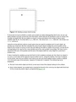
Basic Tasks
When you create an automation solution with STEP 7, there are a series of basic
tasks. The following figure shows the tasks that need to be performed for most
projects and assigns them to a basic procedure. It refers you to the relevant
chapter thus giving you the opportunity of moving through the manual to find task-
related information.
Introducing the Product and Installing the Software
Programming with STEP 7 V5.3
1-2 A5E00261405-01
NO
NO
YES
NO
YES
Install STEP 7
Plan controller concept
and design program structure
Start STEP 7
and create a project
?
Configure hardware now?
Configure hardware and a connection
• Configure modules
• Network stations
• Configure connections to partner
YES
?
Define symbols
Symbolic programming instead of
absolute programming?
YES
?
Create user program
• Program blocks
• Call block in program
• Define local symbols
Create reference data now? (for example, for
debugging)
Generate reference data
Option:
• Program messages
• Configure variables for "Operator Control
and Monitoring"
NO
?
Configure hardware and connection
Download program
Test program and diagnose errors
Print and archive
Have you already congfigured the hardware?
Introducing the Product and Installing the Software
Programming with STEP 7 V5.3
A5E00261405-01
1-3
Alternative Procedures
As shown in the figure above, you have two alternative procedures:
• You can configure the hardware first and then program the blocks.
• You can, however, program the blocks first without configuring the hardware.
This is recommended for service and maintenance work, for example, to
integrate programmed blocks into in an existing project.
Brief Description of the Individual Steps
• Install STEP 7 and license keys
The first time you use STEP 7, install it and transfer the license keys from
diskette to the hard disk (see also Installing STEP 7 and Authorization).
• Plan your controller
Before you work with STEP 7, plan your automation solution from dividing the
process into individual tasks to creating a configuration diagram (see also
Basic Procedure for Planning an Automation Project).
• Design the program structure
Turn the tasks described in the draft of your controller design into a program
structure using the blocks available in STEP 7 (see also Blocks in the User
Program).
• Start STEP 7
You start STEP 7 from the Windows user interface (see also Starting STEP 7).
• Create a project structure
A project is like a folder in which all data are stored in a hierarchical structure
and are available to you at any time. After you have created a project, all other
tasks are executed in this project (see also Project Structure).
• Configure a station
When you configure the station you specify the programmable controller you
want to use; for example, SIMATIC 300, SIMATIC 400, SIMATIC S5 (see also
Inserting Stations).
• Configure hardware
When you configure the hardware you specify in a configuration table which
modules you want to use for your automation solution and which addresses
are to be used to access the modules from the user program. The properties of
the modules can also be assigned using parameters (see also Basic
Procedure for Configuring Hardware).
• Configure networks and communication connections
The basis for communication is a pre-configured network. For this, you will
need to create the subnets required for your automation networks, set the
subnet properties, and set the network connection properties and any
communication connections required for the networked stations (see also
Procedure for Configuring a Subnet).
• Define symbols
You can define local or shared symbols, which have more descriptive names,
in a symbol table to use instead of absolute addresses in your user program
(see also Creating a Symbol Table).
Introducing the Product and Installing the Software
Programming with STEP 7 V5.3
1-4 A5E00261405-01
• Create the program
Using one of the available programming languages create a program linked to
a module or independent of a module and store it as blocks, source files, or
charts (see also Basic Procedure for Creating Logic Blocks and Basic
Information on Programming in STL Source Files).
• S7 only: generate and evaluate reference data
You can make use of these reference data to make debugging and modifying
your user program easier (see also Overview of the Available Reference Data).
• Configure messages
You create block-related messages, for example, with their texts and attributes.
Using the transfer program you transfer the message configuration data
created to the operator interface system database (for example, SIMATIC
WinCC, SIMATIC ProTool), see also Configuring Messages.
• Configure operator control and monitoring variables
You create operator control and monitoring variables once in STEP 7 and
assign them the required attributes. Using the transfer program you transfer
the operator control and monitoring variables created to the database of the
operator interface system WinCC (see also Configuring Variables for Operator
Control and Monitoring).
• Download programs to the programmable controller
S7 only: after all configuration, parameter assignment, and programming tasks
are completed, you can download your entire user program or individual blocks
from it to the programmable controller (programmable module for your
hardware solution). (See also Requirements for Downloading.) The CPU
already contains the operating system.
M7 only: choose a suitable operating system for your automation solution from
a number of different operating systems and transfer this on its own or together
with the user program to the required data medium of the M7 programmable
control system.
• Test programs
S7 only: for testing you can either display the values of variables from your
user program or a CPU, assign values to the variables, and create a variable
table for the variables that you want to display or modify (see also Introduction
to Testing with the Variable Table).
M7 only: test the user program with a high-level language-debugging tool.
• Monitor operation, diagnose hardware
You determine the cause of a module fault by displaying online information
about a module. You determine the causes for errors in user program
processing with the help of the diagnostic buffer and the stack contents. You
can also check whether a user program can run on a particular CPU (see also
Diagnosing Hardware and Displaying Module Information).
• Document the plant
After you have created a project/plant, it makes sense to produce clear
documentation of the project data to make further editing of the project and any
service activities easier (see also Printing Project Documentation). DOCPRO,
the optional tool for creating and managing plant documentation, allows you to
structure the project data, put it into wiring manual form, and print it out in a
common format.
Introducing the Product and Installing the Software
Programming with STEP 7 V5.3
A5E00261405-01
1-5
Specialized Topics
When you create an automation solution there are a number of special topics that
may be of interest to you:
• Multicomputing - Synchronous Operation of Several CPUs (see also
Multicomputing - Synchronous Operation of Several CPUs)
• More than One User Working in a Project (see also More than One User
Editing Projects)
• Working with M7 Systems (see also Procedure for M7 Systems)
1.2 The STEP 7 Standard Package
Standards Used
The SIMATIC programming languages integrated in STEP 7 are compliant with EN
61131-3. The standard package matches the graphic and object oriented operating
philosophy of Windows and runs under the operating system MS Windows 2000
Professional (as of now referred to as Windows 2000) as well as MS Windows XP
Professional (as of now referred to as Windows XP).
Functions of the standard package
The standard software supports you in all phases of the creation process of an
automation task, such as:
• Setting up and managing projects
• Configuring and assigning parameters to hardware and communications
• Managing symbols
• Creating programs, for example, for S7 programmable controllers
• Downloading programs to programmable controllers
• Testing the automation system
• Diagnosing plant failures
The STEP 7 software user interface has been designed to meet the latest
state-of-the-art ergonomics and makes it easy for you to get started.
The documentation for the STEP 7 software product provides all the information
online in the online Help and in electronic manuals in PDF format.