Subcoal ® from coarse rejects of the paper industry as fuel for limekilns doc
Bạn đang xem bản rút gọn của tài liệu. Xem và tải ngay bản đầy đủ của tài liệu tại đây (161.84 KB, 23 trang )
Climate analysis Subcoal
®
Subcoal
®
from coarse rejects
of the paper industry as fuel
for limekilns
Report
Delft, June 2011
Author(s):
Matthijs Otten
Anouk van Grinsven
Harry Croezen
2 June 2011 2.483.1 – Climate analysis Subcoal®
Publication Data
Bibliographical data:
Matthijs Otten, Anouk van Grinsven, Harry Croezen
Climate analysis Subcoal®
Subcoal® from coarse rejects of the paper industry as fuel for limekilns
Delft, CE Delft, June 2011
Waste disposal / Paper industry / Residue / Fuel / Lime / Incineration oven / Energy / Carbon
emissions / Analysis
Publication number: 11.2483.44
CE-publications are available from www.cedelft.eu
Commissioned by: Qlyte.
Further information on this study can be obtained from the contact person Matthijs Otten.
© copyright, CE Delft, Delft
CE Delft
Committed to the Environment
CE Delft is an independent research and consultancy organisation specialised in
developing structural and innovative solutions to environmental problems.
CE Delft’s solutions are characterised in being politically feasible,
technologically sound, economically prudent and socially equitable.
3 June 2011 2.483.1 – Climate analysis Subcoal®
Contents
Summary 5
1 Introduction 7
2 Summary previous study 9
3 Subcoal
®
process 11
4 Climate effects of Subcoal
®
from rejects of the paper industry 13
4.1 System boundaries comparison 13
4.2 Background data 14
4.3 Results 16
5 Effects of Subcoal
®
on CO
2
emissions of lime production 19
5.1 Energy consumption and CO
2
emissions of lime production 19
5.2 Effect of Subcoal
®
on the CO
2
emissions lime production 20
6 Conclusions 21
References 23
4 June 2011 2.483.1 – Climate analysis Subcoal®
5 June 2011 2.483.1 – Climate analysis Subcoal®
Summary
This study compares the climate effects of the processing of coarse rejects
from the paper industry by the Subcoal
®
route with incineration of the rejects
in a waste incineration plant (WIP). A previous study by CE Delft revealed that
for the paper-plastic fraction of household waste, the Subcoal
®
route has a
better climate and overall environmental score as compared to the
incineration in a waste incineration plant. This report shows how the climate
change comparison between the Subcoal
®
and WIP route works out for coarse
rejects from the paper industry. Also for coarse rejects from the paper
industry the Subcoal
®
route has a significant lower impact on climate change
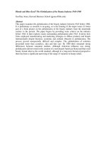
than the WIP route. Per tonne of reject the Subcoal® route avoids 828 kilo
CO
2
extra as compared to an average WIP and 545 kilo CO
2
as compared to high
performance WIP (Figure 1).
Figure 1 Avoided CO
2
emissions of rejects processed in the Subcoal®/limekiln route compared to the
avoided emissions by incineration in WIPs
Avoided CO
2
emissions (kg/ tonne reject)
0
200
400
600
800
1000
1200
1400
WIP average WIP high performance Subcoal/limekiln
For the production of lime this means that when Subcoal® is co-fired at 30%
(on caloric base), the CO
2
emission of the lime production process can be
reduced by 17-18%.
6 June 2011 2.483.1 – Climate analysis Subcoal®
7 June 2011 2.483.1 – Climate analysis Subcoal®
1 Introduction
Subcoal
®
Technology is used to process paper plastic waste fractions into a
substitute for coal or lignite. The fuel pellets can be used as secondary energy
source in industrial furnaces, such as limekilns and cement kilns, coal-fired
power plants and blast furnaces. Subcoal
®
has a caloric value comparable with
lignite.
In a previous study by CE Delft (CE, 2000), the Subcoal
®
route for paper-plastic
fractions (PPF) of a waste sorting installation has been environmentally
analysed and compared to alternative waste disposal routes like incineration in
a waste incineration plant. The study revealed that the Subcoal
®
route reduces
climate change effects and other environmental impacts of the PPF waste as
compared to the waste incineration route.
At the new plant of Qlyte in Farmsum, approximately 45,000 ton of Subcoal
®
is
produced annually from coarse rejects of the paper industry. The Subcoal
®
is
used to substitute lignite in limekilns. As compared to the PPF of a waste
sorting plant, rejects from the paper industry have a different constitution and
most importantly contain much more water. Qlyte has asked CE Delft to
update the climate change analysis of the Subcoal
®
route in comparison with
incineration for coarse rejects of the paper industry in a waste incineration
plant. The update includes the improvements of the energy conversion
efficiency of waste incineration plants since 2000. Furthermore the climate
impact on lime production is assessed.
8 June 2011 2.483.1 – Climate analysis Subcoal®
9 June 2011 2.483.1 – Climate analysis Subcoal®
2 Summary previous study
In CE, 2000 the effect of substituting coal by Subcoal
®
derived from paper-
plastic fractions (PPF) of municipal solid waste has been compared with two
other treatments:
1. Co-firing of PPF in a cement kiln, substituting lignite.
2. Incineration in a waste incinerator plant.
In case of the Subcoal
®
route the PPF is shreddered, dried and pelletized.
In case of recovery in the cement kiln the PPF is baled before exporting and
shreddered at the cement kiln.
Due to the focus of the research on the environmental friendly ways to recover
plastic packages, only the plastic fraction of the PPF was assessed.
The study compared the integral incineration of plastic in household waste to
treatments in which 36% of the plastics was separated out and processed
either in the cement kiln route or the Subcoal
®
route. A summary of the main
results is presented in Table 1.
Table 1 Environmental score
Route Way of processing Environmental
indicators
(10
-9
year per ton
plastic in RDF)
(lower=better
CO
2
emission
(kg/tonne plastic
in RDF)
(lower=better)
Subcoal
®
35% plastic Subcoal
®
route
65% plastic in waste incinerator
15.7 704
Cement kiln 35% plastic in cement kiln
65% plastic in waste incinerator
17.1 659
Waste
incinerator
100% plastic in waste incinerator 28.5 1,600
The routes of Subcoal
®
and cement kiln have similar environmental impacts.
Due to the pre-treatment the Subcoal
®
has a somewhat lower overall impact
on the environment mainly due to lower acidification impacts.
The use of plastic in the cement industry has a somewhat lower effect on
climate change.
Overall it was concluded that the Subcoal
®
process and recovery in a cement
kiln results in a 50% reduction of the total environmental effects compared to
the waste incinerator route. This result is mainly due to the direct substitution
of coal in the two routes, and therefore the severe environmental impacts of
coal use.
10 June 2011 2.483.1 – Climate analysis Subcoal®
11 June 2011 2.483.1 – Climate analysis Subcoal®
3 Subcoal
®
process
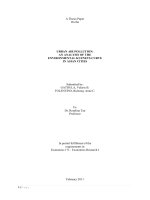
Figure 2 gives an overview of the production of Subcoal
®
fuel from coarse
rejects of paper production.
After shreddering the rejects (45% water content), a sifter separates out heavy
part such as stones and metals. By means of water press excess of water is
removed after which the material is further dried thermally to a water content
below 10%. The water vapour is released into the atmosphere via a cyclone
and an air scrubber. During the process ferro and non-ferro materials are
removed by Eddy current separators and magnets. PCV is being removed by
optical separation techniques. Finally the product is pelletized.
Figure 2 Simplified process diagram of the Subcoal
®
production process
12 June 2011 2.483.1 – Climate analysis Subcoal®
13 June 2011 2.483.1 – Climate analysis Subcoal®
4 Climate effects of Subcoal
®
from
rejects of the paper industry
4.1 System boundaries comparison
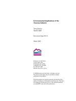
Figure 3 gives an overview of the (avoided) CO
2
emissions involved with
treatment of rejects in the Subcoal
®
/limekiln route on the one hand and the
waste incineration plant (WIP) route on the other hand.
The CO
2
emissions in the WIP route concern the CO
2
emission of transport of
the rejects to the WIP, and emissions of incineration of the rejects. On the
other hand emissions are avoided through net electricity production and heat
supply by the WIP.
The CO
2
emissions in the Subcoal
®
route concern the CO
2
emission of transport
of rejects to the Subcoal® production plant, CO
2
emissions of gas, diesel and
electricity consumption in the Subcoal
®
production process, and emissions of
incineration of the rejects. Emissions are avoided through the substitution of
lignite by co-incineration in a limekiln. The CO
2
emissions of incineration are
equal in both processes and will therefore be left out of the comparison.
Figure 3 Scheme CO
2
emission of WIP and Subcoal
®
route
Avoided CO
2
- Electricity production
- Heat delivered
Incineration in WIP with
electricity and heat production
Emmitted CO
2
Incineration of rejects/subcoal
Equal for both processes
Rejects
Co-incineration in lime kiln
Avoided CO
2
- Substitution of lignite
Emitted CO
2
-Gas use
- Electricity use
-Diesel use
Subcoal®Subcoal® proces
WIP route
Subcoal® route
T
T
T
* T indicates the CO
2
emissions of transport.
14 June 2011 2.483.1 – Climate analysis Subcoal®
For clarity reasons the (relatively low) CO
2
emissions related to the use of
additives (NaOH, Ca(OH)
2
and NH
4
OH) for flue gas cleaning in the WIP and the
avoid use of additives of flue gas cleaning of electricity production in a power
plant are not shown in Figure 3. These CO
2
emission, however, are accounted
for in the analysis below.
Also omitted for clarity reasons are the CO
2
emissions related to the removed
ferro, non-ferro parts (2% of rejects) and PVC parts (3% of rejects).
PVC contents in both routes are (finally) incinerated in a WIP. The related
CO
2
emissions are therefore the same. Ferro and non-ferro parts in both routes
are separated out and send for recycling. It is assumed that the processing
efficiency of the metal parts in both routes is comparable and that the related
CO
2
emissions are the same.
1
Waste incineration plants vary in their energy recovery efficiency and
therefore the avoided CO
2
emissions vary per installation. In the following
analysis the Subcoal
®
/limekiln route will therefore be compared to both an
average Dutch WIP and a high performance WIP.
4.2 Background data
4.2.1 Caloric values Rejects and Subcoal®,
The amount of electricity and heat generation in a WIP and the amount of
substituted lignite depends on the caloric value of the reject and the caloric
value of the Subcoal® produced from it, respectively. The caloric values on
their turn depend on the dry material and water contents. Data on the
composition of the reject and Subcoal® are given in Table 2. In the Subcoal®
process 5% of the rejects is removed as metal or PVC and 41% as water, leaving
54% of the reject mass as Subcoal®, containing 8% of water.
Table 2 Composition rejects and Subcoal®
Content (mass%)
Moisture content rejects 45%
PVC and metal content rejects 5%
Dry content rejects excl. PVC and metals 50%
Subcoal® content in rejects 54%
Moisture content Subcoal® 8%
Source: Qlyte.
Given the caloric value of 22 megajoules per kilo for Subcoal® the other
caloric values in Table 3 were calculated. The reject (excl. PVC) in the
WIP route delivers 11.0 megajoule per kilo reject. In the Subcoal® route
12.0 megajoule per kilo is delivered. Due to the water removal the delivered
caloric value of the rejects is increased by 1.0 megajoule per kilo reject.
1
In reality the Subcoal
®
route might be more efficient in separating out metals from the
rejects than the WIP is in separating out metals form the incineration slags. A 20% higher
efficiency in the Subcoal
®
route might be realistic and would result in 20 kg CO
2
extra avoided
emission for the Subcoal route as compared to the WPI route.
15 June 2011 2.483.1 – Climate analysis Subcoal®
Table 3 Caloric values rejects and Subcoal®
Source
Net Caloric value Subcoal® (MJ/kg) 22.0 SGS
Net Caloric value Subcoal® on dry basis (MJ kg)
2
24.1 SGS/calculated
Net caloric value rejects (MJ/kg reject)
3
11.0 Calculated
Caloric value Subcoal® (MJ/kg reject)
4
12.0 Calculated
4.2.2 Energy consumption and avoided energy consumption Subcoal® and
WIP route
The electricity, gas and diesel consumption in the Subcoal® production process
and the average assumed transport distances are given in Table 4.
Table 4 Electricity and fuel consumption of Subcoal® process
Electricity consumption Subcoal® process (kWh/tonne reject) 69 Qlyte
Gas consumption Subcoal® process (m
3
/tonne reject) 20 Qlyte
Diesel consumption Shovel (liter/tonne reject) 0.38 Qlyte
Truck transport to Subcoal® plant (km) 230 Utrecht-Varmsum
Sea transport (km) 1300 Qlyte
In the Subcoal
®
route, every kilo of reject delivers 12.0 MJ of Subcoal
®
substituting 12.0 MJ of lignite and the corresponding CO
2
emissions (Table 6).
In the WIP route every kilo of reject delivers 11.0 M J of fuel in a WIP. Table 5
gives the conversion factors for electricity and heat production of an average
Dutch WIP and of a high performance WIP with theoretical energy efficiency of
1.
5
The net electricity and heat production by a WIP avoids conventional
electricity and heat production.
In addition Table 1 gives the additives consumption for a WIP and for (avoided)
electricity generation and the transport distance.
2
24.1 MJ kg for Subcoal® dry was calculated from 22.0, taking 2.44 MJ/kg for the evaporation
enthalpy of water, as follows: (22+2.44* 8%)/(1-8%).
3
Not included is the caloric value of 3% PVC. The value of 11.0 MJ/kg is calculated from
24.1 MJ/kg for Subcoal
®
(dry), taking 2.44 MJ/kg for the evaporation enthalpy of water,
as follows: 50% · 24.1 - 45% · 2.44.
4
12.0 MJ/ was calculated as follows: 54%··22.
5
The chosen electrical and thermal efficiency contribute both for 50% to an overall Energy
efficiency of 1 according to the R1 formula as defined by (Lap2, 2009) . A WIP with energy
efficiency of 1 matches the efficiency of standard electricity or heat generation in the
Netherlands (Lap2, 2009).
16 June 2011 2.483.1 – Climate analysis Subcoal®
Table 5 Input values WIPs
Energy consumption Subcoal
®
process Value Source
Net electric efficiency WIP Dutch average 14% Agentschap NL, 2011
Net heat delivered WIP Dutch average 16% Agentschap NL, 2011
Net electric efficiency high efficiency WIP 19% Assumption EE=1
5
Net heat delivered high efficiency WIP 44% Assumption EE=1
5
NaOH use WIP (kg/ton reject) 6.2 AOO, 2002/SGS
Ca(OH)
2
use WIP (kg/ton reject) 3.2 AOO, 2002/SGS
NH4OH (25%) use WIP (kg/ton reject) 0.7 AOO, 2002/SGS
Avoided Ca(OH)
2
use power plant (kg/GJ
e
)
6
0.26 AOO, 2002/SGS
Avoided NH4OH (25%) power plant (kg/GJ
e
) 0.16 AOO, 2002/SGS
Truck transport to WIP (km) 40 AOO, 2002
4.2.3 CO
2
emission factors
The comparison of the CO
2
emission of the WIP route and the Subcoal® route
involves avoided CO
2
emissions of electricity and heat generation, avoided use
of lignite, the CO
2
emission from electricity gas and diesel use, the CO
2
emission factors for the use of additives in a WIP and the CO
2
emissions of
transport. The emission factors for these components are given in Table 6.
Table 6 CO
2
emission factors
CO
2
emission factors Value Source
Electricity mix NL (kg CO
2
/MJ
e
) 161 Agentschap NL, 2010
Heat generation NL (kg CO
2
/MJ
t
) 63 Ecoinvent 2.2
Lignite fired in power plant DE ((kg/CO
2
/MJ) 112 Ecoinvent 2.2
Gas fired (kg/CO
2
/MJ) 60 Ecoinvent 2.2
NaOH 20% in water (kg CO
2
/kg NaOH) 0,440 Ecoinvent 2.2
Ca(OH)
2
(kg CO
2
/kg Ca(OH)
2
) 0,758 Ecoinvent 2.2
NH4OH 25% in water (kg/CO
2
/kg) 0,5 Ecoinvent 2.2
Diesel consumption (kg CO
2
/litre Diesel) 3.32 CE, 2008
Truck trailer GVW 40 tonne (kg CO
2
/tkm) 76 CE, 2008
Product sea tanker-2 tonne capacity (kg CO
2
/tkm) 53 CE, 2008
4.3 Results
Table 7 gives an overview of the CO
2
emissions for the comparison of the WIP
and Subcoal® route. Table 7 makes clear that the difference in avoided
CO
2
emissions between WIP and Subcoal® route is crucial for the comparison.
The extra CO
2
emission of the subcoal process and transport are relatively
small as compared to the extra avoided emissions in the Subcoal® route.
The direct substitution of lignite in the Subcoal® route results in high avoided
CO
2
emissions. In the WIP route the electricity and heat produced by the
WIP substitute conventional electricity and heat that are generated with fuels
with a lower CO
2
intensity than lignite. Moreover an average WIP is less
efficient in energy conversion than conventional power plants.
Per tonne of reject the Subcoal® route avoids 828 kilo CO
2
extra as compared
to an average WIP and 545 kilo CO
2
as compared to high performance WIP.
6
Assumed is 25% electricity generation in a coal-fired power plant.
17 June 2011 2.483.1 – Climate analysis Subcoal®
Table 7 Overview CO
2
emissions WIP and Subcoal® route
WIP
average
WIP high
performance
Subcoal®/
limekiln
Avoided CO
2
emissions (electricity and heat
production and substitution lignite)
- 352 - 635 - 1,339
Emission of processing (use of additives, gas,
diesel and electricity)
5 5 81
Transport CO
2
emissions 3 3 86
Total emissions - 344 - 627 - 1,172
Figure 4 illustrates the difference in avoided emissions of the Subcoal® route
and the two kinds of WIPs. CO
2
emissions of transport, and electricity and gas
consumption have been subtracted from the avoided emissions.
Figure 4 Avoided CO
2
emissions of rejects processed in the Subcoal®/limekiln route compared to the
avoided emissions by incineration in WIPs
Avoided CO
2
emissions (kg/ tonne reject)
0
200
400
600
800
1000
1200
1400
WIP average WIP high performance Subcoal/limekiln
18 June 2011 2.483.1 – Climate analysis Subcoal®
19 June 2011 2.483.1 – Climate analysis Subcoal®
5 Effects of Subcoal
®
on CO
2
emissions of lime production
5.1 Energy consumption and CO
2
emissions of lime production
The production of lime involves the use of energy-intensive processes.
The lime burning process is the principal user of energy. Energy use depends
on several factors including the quality of limestone used, moisture content,
the fuel used and the design of kiln. Table 8 gives an overview of the thermal
energy consumption for several types for kilns according to best available
technique (BAT) standards (EA, 2010). The electricity consumption of a
limekiln is in the order of 375 MJ
e
per tonne of lime (Ecoinvent 2.2).
Table 8 BAT associated thermal energy consumption for various kiln types
Kiln type Thermal energy
consumption1
GJ/t
Long rotary kilns (LRK) 6.0–9.2
Rotary kilns with pre-heater (PRK) 5.1–7.8
Parallel flow regenerative kilns (PFRK) 3.2–4.2
Annual shaft kilns (ASK) 3.3–4.9
Mixed feed shaft kilns (MFSK) 3.4–4.7
Other kilns (OK) 3.5–7.0
Source: EA, 2010.
The lime production process involves CO
2
emissions of the decomposition of
limestone (calcium carbonate) on the one hand and the CO
2
emissions of
combustion and electricity consumption on the other hand.
The manufacture of one tonne of (quick)lime (calcium oxide) involves the
decomposition of calcium carbonate, with the formation of 785 kg
7
of CO
2
.
In some applications, such as when used as mortar or PCC
8
this CO
2
is
reabsorbed with the formation of limestone (CaCO
3
).
The CO
2
emissions of electricity consumption are around 50 kg per tonne of
lime
9
. The CO
2
emissions of combustion depend on the thermal energy
consumption and the fuel used. Typically, Subcoal
®
is co-fired in rotary kilns
fired with lignite. For the range of energy consumptions in Table 8 the CO
2
emissions for a rotary kiln fired 100% on lignite the CO
2
emissions are in the
range of 570-1,030 kg CO
2
per tonne of lime (excl. CO
2
of electricity
consumption and CO
2
process emissions from limestone decomposition).
The CO
2
emissions for the production of lime in a lignite fired rotary kiln are
summarized in Table 9.
7
Molar weight CaO = 56 molar weight CO
2
= 44. Per ton CaO 44/56*1,000 kg CO
2
is released.
8
Precipitated calcium carbonate.
9
Assuming 140 kg CO
2
/GJ electricity medium voltage EU average.
20 June 2011 2.483.1 – Climate analysis Subcoal®
Table 9 CO
2
emission lime production in a rotary kiln
CO
2
emission rotary kiln kg CO
2
/tonne lime
Emissions of lignite combustion 571-1,030
Emissions of electricity consumption 50
Emissions of CaCO
3
decomposition 785
5.2 Effect of Subcoal
®
on the CO
2
emissions lime production
Per tonne of reject the Subcoal® route avoids 828 kilo CO
2
extra as compared
to an average WIP. This figure corresponds to 69 kilo CO
2
per gigajoule
substituted lignite.
10
Subcoal
®
can be co-fired in a lignite-fired limekiln up to a
caloric value of 30%. This means that for every gigajoule fuel, 0.3 gigajoules
lignite can be substituted by Subcoal
®
. The CO
2
emissions of 112 kg CO
2
per
gigajoule fuel (100% lignite) can therefore be reduced by 21 kg CO
2
.
11
This means that the CO
2
emissions of fuel combustion in a rotary kiln can be
reduced by 19% when Subcoal
®
is co-fired to the maximum extent.
For the range of energy consumption in a rotary kiln given in Table 8 this
corresponds to a reduction of 106-191 kilo CO
2
per tonne lime. As compared to
the total CO
2
emissions in the production process (excl. decomposition) this
corresponds to a reduction of 17-18%.
10
The reject in the Subcoal
®
route delivers 12.0 gigajoules pet tonne.
11
69 kg/GJ * 0.3 GJ.
21 June 2011 2.483.1 – Climate analysis Subcoal®
6 Conclusions
In this study the climate effects of the processing of coarse rejects from the
paper industry through the Subcoal
®
route have been compared with
incineration of the rejects in a waste incineration plant (WIP). As has been
shown in a previous study by CE Delft, the Subcoal
®
route has a lower impact
on climate change than the WIP route.
Per tonne of reject the Subcoal® route avoids 828 kilo CO
2
extra as compared
to an average WIP and 545 kilo CO
2
as compared to high performance WPI
(Figure 5).
Figure 5 Avoided CO
2
emissions of rejects processed in the Subcoal®/limekiln route compared to the
avoided emissions by incineration in WIPs
Avoided CO
2
emissions (kg/ tonne reject)
0
200
400
600
800
1000
1200
1400
WIP average WIP high performance Subcoal/limekiln
For the production of lime this means that when Subcoal® is co-fired at 30%
(on caloric base), the CO
2
emission of the lime production process can be
reduced by 17-18%.
22 June 2011 2.483.1 – Climate analysis Subcoal®
23 June 2011 2.483.1 – Climate analysis Subcoal®
References
Agentschap NL, 2010
Simone te Buck, Bregje van Keulen, Lex Bosselaar, Timo Gerlagh
Protocol monitoring Hernieuwbare energie, Update 2010: Methodiek voor het
berekenen en registreren van de bijdrage van hernieuwbare energiebronnen
S.l. : Agentschap NL, 2010
Agentschap NL, 2011
Average energy efficiency of waste incineration plants in 2009
Personal communication with Agentschap NL
AOO, 2002
Milieueffectrapport Landelijk Afvalbeheerplan (LAP): Achtergronddocument
A1 balansen, reststoffen en uitloging
Utrecht : Afval Overleg Orgaan (AOO), 2002
CE, 2000
H.J. (Harry) Croezen, G.C. (Geert) Bergsma
Subcoal milieukundig Beoordeeld
Delft : CE Delft, 2000
CE, 2008
L.C. (Eelco) den Boer, F.P.E. (Femke) Brouwer, H.P. (Huib) van Essen
STREAM versie 2.0: Studie naar de emissies van alle modaliteiten
Delft : CE Delft, 2008
EA, 2010
How to comply with your environmental permit
Additional guidance for: The lime industry (EPR 3.01b)
Bristol : Environmental Agency (EA), 2010
Ecoinvent 2.2
Website database of the Swiss Centre for Life Cycle Inventories
Accessed: June 1, 2011
Lap2, 2009
O. van Hunnik (SenterNovem)
Memo: Advies aanvragen R1-status AVI-installaties
www.lap2.nl
Accessed: June 1, 2011
SGS, 2010
Analysis report of Subcoal® by SGS Spijkenisse
Spijkenisse : SGS Nerdeland BV., 2010