Influence of support surface roughness on zeolite membrane quality
Bạn đang xem bản rút gọn của tài liệu. Xem và tải ngay bản đầy đủ của tài liệu tại đây (9.13 MB, 5 trang )
Microporous and Mesoporous Materials 308 (2020) 110546
Contents lists available at ScienceDirect
Microporous and Mesoporous Materials
journal homepage: />
Influence of support surface roughness on zeolite membrane quality
Ming Zhou *, Mohammad Sadegh Nabavi , Jonas Hedlund
Chemical Technology, Luleå University of Technology, SE-971 87, Luleå, Sweden
A R T I C L E I N F O
A B S T R A C T
Keywords:
Defects
Permporometry
Polishing
SEM
Substrate
Two main types of morphological features resulting in surface roughness were observed on alumina discs used as
supports for zeolite membranes. These features can be described as hills and pits and it was shown that defects as
cracks formed in the zeolite film at these locations of the support. It was demonstrated that the roughness of the
support can be reduced significantly by a polishing strategy developed in this paper. Finally, zeolite MFI
membranes grown on the polished support shows remarkably improved quality as compared to films grown on
non-polished supports.
1. Introduction
Zeolite membranes are microporous inorganic membranes [1]. They
have uniform pore size and high chemical stability [2,3]. Therefore,
these materials can be utilized in a large number of applications where
polymeric membranes are not applicable [4]. Membrane technologies
are suitable for liquid [5–7] and gas separation [8–10], and in reactors
[11,12], and as chemical sensors [13].
The MFI framework has two types of channels, zigzag channels (5.1
× 5.5 Å) and straight channels (5.3 × 5.6 Å) [14]. Based on the Si/Al
ratio, MFI is classified as silicalite-1 (Si/Al ratio higher than 200) or
ZSM-5 (Si/Al ratio is 10–200) [15]. The channel diameter is suitable for
separation of hydrocarbons, and consequently this framework attracted
much attention in gas separation [16–18]. However, it has been reported
that defects in the zeolite film may reduce the separation performance
[19,20].
In a defect free zeolite membrane, permeation would occur only
through the zeolite pores. However, in reality, membranes contain de
fects and permeation also occurs in these defects. Open grain boundaries
is one of the most common types of defects [21], and pinholes are
another type of defect [22,23] and the latter can be reduced by a ho
mogeneous seed layer [24]. Membranes may also crack during calci
nation after synthesis due to two main reasons. Firstly, calcination
removes the structure-directing agent and any other volatile species left
in the micropores. This results in contraction of the zeolite crystals,
which may result in crack formation. Secondly, the thermal expansion
mismatch between support and zeolite film can lead to formation of
cracks during calcination [25]. There are alternatives to regular
calcination reported in the literature such as ozonication and rapid
thermal processing (RTP) that may be used to reduce the problem
[26–28]. In present work, the effect of surface roughness of the mac
roporous alumina support on the quality of zeolite MFI membrane, i.e.
cracks formation in the areas of hills and pits is investigated. A novel
polishing approach that can reduce roughness and avoid cracking in
zeolite membranes is reported for the first time.
2. Experimental
2.1. Membrane preparation
Graded porous alpha-alumina disks (Fraunhofer IKTS, Germany)
with a diameter of 25 mm and a total thickness of 3 mm were used as
supports, it contains a 40 μm thick top layer with a pore size of 100 nm
and a bottom main part with a pore size of 3 μm. The washed alumina
supports were carefully polished by hand using #4000 SiC paper
(average grain size 5 μm, Struers) until a shiny wet surface was
observed. The alumina discs were first polished on SiC paper supported
on a large flat hard surface, and then on a soft rubber surface with a
decreasing diameter of ca 23 mm, 18 mm, 12 mm, 8 mm in sequence.
The reason for this two steps polishing method is that the disk surface is
not pure flat, it contains areas of raised ‘plateaus’ and sunken ‘basins’. In
the first step, simply polish the surface on a flat SiC paper to remove all
the plateaus and hills-shaped rough areas, this process can change all the
protruding parts of the support into shiny surface. In the second step, the
basin-shaped rough area on the disk surface cannot be touched by a flat
SiC paper, here a round soft rubber mat (0.8 mm thick) was put under
* Corresponding author.
E-mail address: (M. Zhou).
/>Received 20 June 2020; Received in revised form 23 July 2020; Accepted 4 August 2020
Available online 8 August 2020
1387-1811/© 2021 The Authors. Published by Elsevier Inc. This is an open access article under the CC BY license ( />
M. Zhou et al.
Microporous and Mesoporous Materials 308 (2020) 110546
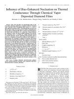
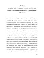
Fig. 1. SEM images of a hill a) and a pit b) at the surface of a non-polished alumina disc, cracks in the zeolite film at the foot of a hill c), and at the bottom of a pit d).
the SiC paper, which make the paper protruding and touching the basin
bottom of the disk surface, in this way the polishing is effective and can
change all the lower parts on the support into smooth surface. In order to
remove the debris formed after polishing, the substrates were auto
claved in DI water at 180 ◦ C for 24 h.
H-ZSM-5 membranes with a thickness of ca. 0.5 μm and a Si/Al ratio
of 139 [29] were prepared as described in detail earlier [30] and briefly
here. Prior to film synthesis, the supports were masked as described
elsewhere [16] and then seeded with colloidal MFI crystals with 50 nm
diameter. After seeding, the supports were rinsed with a filtered (0.1
mm) 0.1 M aqueous NH3 solution to remove excess seed crystals. The
film synthesis was carried out for 70 h at 88 ◦ C in a synthesis solution
with a molar composition of 3TPAOH : 25SiO2 : 1450H2O : 100C2H5OH.
The ethanol released from TEOS hydrolysis form azeotropes with boiling
point lower than 100 ◦ C, to reduce turbulent of the synthesis solution,
lower temperature was chosen in this study. After the synthesis, the
membranes were rinsed with a 0.1 M ammonia solution and then
calcined for 6 h at 500 ◦ C at a heating rate of 0.2 ◦ C min− 1 and a cooling
rate of 0.3 ◦ C min− 1.
2.3. SEM characterization
SEM images were recorded using extreme-high-resolution scanning
electron microscopy (XHR-SEM), using a Magellan 400 (the FEI Com
pany, Eindhoven, the Netherlands) instrument and no conductive
coating was applied to the samples.
2.4. 3D optical surface profile measurement
A Wyko 1100NT 3D optical surface profiler was used to measure the
surface roughness, using vertical scanning interferometry (VSI) of white
light. A magnification of 2.5 was used and the data was processed using
the Veeco software.
3. Results and discussion
In the first step, non-polished alumina discs were investigated by
SEM to reveal the morphology of the surface. Two main types of
morphological features were observed and these can be described as
hills and pits as shown in Fig. 1a) and b), respectively. The main dif
ference between individual non-polished discs was the density of hills
and pits. Fig. 1c) and d) show SEM images of a ZSM-5 membrane
recorded at the location of a hill and pit in the support, respectively. It
was revealed that cracks mainly formed in the film at the foot of the hills
and at the bottom of the pits as indicated by the insets in Fig. 1c) and d),
respectively. Thermal expansion of support and contraction of zeolite
membrane upon template removal is not the main cause for these cracks.
The membrane at hill and pit areas bend more sharply, hence the high
curvature in these types of surfaces deviate from being a flat membrane
cause the cracks formation.
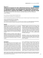
For a non-polished support, the thickness of the alumina top layer is
40 μm, Fig. 2 a). After polishing of the support, the thickness of the top
layer reduced to 30 μm, Fig. 2 b). During polishing, the applied pressure
(P) had a significant influence on the final smoothness of the alumina
2.2. Permporometry
For characterization by permporometry [30], the membranes were
mounted in stainless steel cells sealed by graphite gaskets (Eriks, the
Netherlands). Then, the cell was heated to 300 ◦ C for 6 h in a flow of
pure helium with a heating rate of 1 ◦ C min− 1 followed by natural
cooling. Permporometry was carried out at room temperature using a
total pressure difference across the membrane of 1 atm. The permeate
was kept at atmospheric pressure. The relative pressure of n-hexane was
increased stepwise from 0 to ca. 1. The system was allowed to reach
steady-state at each step. A digital flow meter and a soap bubble flow
meter were employed to measure the volumetric flow rate of the
permeate. The defect distribution was calculated as reported previously
[20].
2
M. Zhou et al.
Microporous and Mesoporous Materials 308 (2020) 110546
Fig. 2. SEM images of the cross section of non-polished a) and polished b) alumina supports, schematic drawing of the polishing process c), camera image of a
polished alumina disc d).
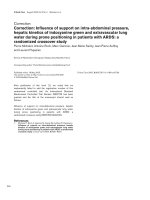
Fig. 3. SEM images and 3D optical surface profiles of non-polished alumina surface a)-c), polished alumina surface with remaining scratches d)-f), polished alumina
with smooth surface g)-i).
surface. The pressure was estimated by simply dividing the force applied
on the backside of the support with the area of the whole support. By P ˃
2000 Pa, a smooth surface with some remaining scratches was produced.
When the pressure was reduced to ca 1000 Pa, a smooth and shiny
surface was obtained, as illustrated schematically in Fig. 2 c), and by a
camera image d).
Fig. 3a) shows a SEM image of a relatively large hill with a height
certainly exceeding 2 μm on a non-polished support. The 3D optical
3
M. Zhou et al.
Microporous and Mesoporous Materials 308 (2020) 110546
Fig. 4. SEM images of small defect on polished surface a) and b), permporometry data c) of membranes grown on non-polished alumina supports (1), (2) and
membranes grown on polished supports (3), (4), schematic illustration of surface roughness induced defects in zeolite membranes d).
surface profiles of a non-polished support at low and high magnification
are illustrated in Fig. 2b) and c), respectively. These profiles illustrate
the presence of numerous hills higher than 2.0 μm (dark red) and that
the average roughness Ra is 907 nm. Fig. 3d) shows an SEM image of a
polished alumina surface using an applied pressure larger than 2000 Pa
during polishing. Scratches with a width of 3–5 μm (similar to the SiC
grain size) can be observed throughout the whole surface. The scratches
are also observed in the 3D optical profile, Fig. 3e). However, the pol
ishing reduced the average roughness Ra to 328 nm and removed most of
the hills, Fig. 3f). By polishing the surface using a pressure of 1000 Pa, a
smooth surface without scratches and hills with an average roughness Ra
as low as 216 nm was achieved, as shown in Fig. 3g), h) and i). This Ra is
comparable to the grain size of the alumina support, i.e. ~150 nm.
Even after polishing of the support, a few shallow pits still remained
in the top-layer of the support, which resulted in smaller cracks with a
width of ca 20 nm in the membrane as illustrated in Fig. 4a) and b).
Before calcination, the single gas helium permeance of the membrane is
< 0.1 × 10− 7 mol m− 2 s− 1 Pa− 1, which means there was not crack in
synthesized membrane and proves the cracks are formed during calci
nation. However, the concentration of these defects is reduced by the
polishing as confirmed by permporometry data shown in Fig. 4c. Line
(1) and line (2) are pormporometry curves of membranes grown on nonpolished alumina surfaces. The total relative areas of defects > 20 nm
are 2.5 × 10− 5 and 1.6 × 10− 5, for these two samples respectively. Line
(3) and line (4) are permporometry data of membranes grown on pol
ished alumina supports. The total relative areas of defects > 20 nm are as
low as 1.2 × 10− 5 and 0.6 × 10− 5, respectively. These two curves are
similar to the best results we measured previously for non-polished
supports [20]. The permporometry results demonstrate that the pol
ishing strategy developed in this paper can decrease the amount of
larger defects (cracks) in the membrane.
4. Conclusion
The surface roughness of alumina supports influence the quality of
zeolite MFI membranes. Micron-sized hills and pits are observed on the
supports and cracks in the membrane form at the foot and bottom of
these hills and pits, respectively. The hills and some pits could be
removed by a delicate polishing approach designed in this paper, and
the average roughness of the alumina surface could be reduced. Zeolite
membranes grown on the polished support shows significantly improved
quality. We anticipate this polishing strategy will have impacts on the
fabrication of defect-free zeolite membranes, which will opens up po
tential for improved performances in the future.
CRediT authorship contribution statement
Ming Zhou: Conceptualization, Methodology, Data curation, Inves
tigation, Methodology, Writing - original draft, Writing - review &
editing. Mohammad Sadegh Nabavi: Data curation, Methodology,
Writing - original draft. Jonas Hedlund: Conceptualization, Funding
acquisition, Project administration, Supervision, Writing - review &
editing.
Declaration of competing interest
The authors declare that they have no known competing financial
interests or personal relationships that could have appeared to influence
the work reported in this paper.
Acknowledgments
The authors acknowledge Bio4Energy, and The Swedish Research
4
M. Zhou et al.
Microporous and Mesoporous Materials 308 (2020) 110546
Council for financially supporting this work.
[15] R. Szostak, Molecular Sieves-Principles of Synthesis and Identification, Springer,
1989.
[16] L. Yu, S. Fouladvand, M. Grahn, J. Hedlund, Ultra-thin MFI membranes with
different Si/Al ratios for CO2/CH4 separation, Microporous Mesoporous Mater. 284
(2019) 258–264.
[17] X. Feng, Z. Zong, S.K. Elsaidi, J.B. Jasinski, R. Krishna, P.K. Thallapally, M.
A. Carreon, Kr/Xe separation over a chabazite zeolite membrane, J. Am. Chem.
Soc. 138 (2016) 9791–9794.
[18] L. Yu, M. Nobandegani, A. Holmgren, J. Hedlund, Highly permeable and selective
tubular zeolite CHA membranes, J. Membr. Sci. 588 (2019) 117224.
[19] X. Liu, Y. Liu, L. Xu, B. Zhang, L. Ma, Spreading-wetting method for highly
reproducible tertiary growth of perfective bilayer TS-1 membranes, Appl. Surf. Sci.
343 (2015) 77–87.
[20] J. Hedlund, D. Korelskiy, L. Sandstră
om, J. Lindmark, Permporometry analysis of
zeolite membranes, J. Membr. Sci. 345 (2009) 276–287.
[21] J. Choi, H.K. Jeong, M.A. Snyder, J.A. Stoeger, R.I. Masel, M. Tsapatsis, Grain
boundary defect elimination in a zeolite membrane by rapid thermal processing,
Science 325 (2009) 590–593.
[22] H. Maghsoudi, Defects of zeolite membranes: characterization, modification and
post-treatment techniques, Separ. Purif. Rev. 45 (2016) 169–192.
[23] M. Noack, P. Kă
olsch, A. Dittmar, M. Stă
ohr, G. Georgi, M. Schneider,
U. Dingerdissen, A. Feldhoff, J. Caro, Proof of the ISS-concept for LTA and FAU
membranes and their characterization by extended gas permeation studies,
Microporous Mesoporous Mater. 102 (2007) 1–20.
[24] M.P. Titus, J. Llorens, F. Cunill, R. Mallada, J. Santamaría, Preparation of zeolite
NaA membranes on the inner side of tubular supports by means of a controlled
seeding technique, Catal. Today 104 (2005) 281–287.
[25] M.J. den Exter, H. van Bekkum, C.J.M. Rijn, F. Kapteijn, J.A. Moulijn,
H. Schellevis, C.I.N. Beenakker, Stability of oriented silicalite-1 films in view of
zeolite membrane preparation, Zeolites 19 (1997) 13–20.
[26] M.C. Schillo, I.S. Park, W.V. Chiu, H. Verweij, Rapid thermal processing of
inorganic membranes, J. Membr. Sci. 362 (2010) 127–133.
[27] T. Lee, J. Choi, M. Tsapatsis, On the performance of c-oriented MFI zeolite
Membranes treated by rapid thermal processing, J. Membr. Sci. 436 (2013) 79–89.
[28] J. Kuhn, S. Sutanto, J. Gascon, J. Gross, F. Kapteijn, Performance and stability of
multi-channel MFI zeolite membranes detemplated by calcination and ozonication
in ethanol/water pervaporation, J. Membr. Sci. 339 (2009) 261–274.
[29] D. Korelskiy, M. Grahn, J. Mouzon, J. Hedlund, Characterization of flow-through
micropores in MFI membranes by permporometry, J. Membr. Sci. 417–418 (2012)
183–192.
[30] L. Yu, A. Holmgren, J. Hedlund, A novel method for fabrication of high-flux zeolite
membranes on supports with arbitrary geometry, J. Mater. Chem. A 7 (2019)
10325–10330.
References
[1] N. Rangnekar, N. Mittal, B. Elyassi, J. Caro, M. Tsapatsis, Zeolite membranes – a
review and comparison with MOFs, Chem. Soc. Rev. 44 (2015) 7128–7154.
[2] N. Kosinov, J. Gascon, F. Kapteijn, E.J.M. Hensen, Recent developments in zeolite
membranes for gas separation, J. Membr. Sci. 499 (2016) 65–79.
[3] Y.S. Lin, M.C. Duke, Recent progress in polycrystalline zeolite membrane research,
Curr. Opin. Chem. Eng. 2 (2013) 209–216.
[4] M. Padaki, R. Surya Murali, M.S. Abdullah, N. Misdan, A. Moslehyani, M.A. Kassim,
N. Hilal, A.F. Ismail, Membrane technology enhancement in oil–water separation,
Rev. Desalination 357 (2015) 197–207.
[5] L. Yu, D. Korelskiy, M. Grahn, J. Hedlund, Very high flux MFI membranes for
alcohol recovery via pervaporation at high temperature and pressure, Separ. Purif.
Technol. 153 (2015) 138145.
[6] H. Zhou, D. Korelskiy, E. Sjă
oberg, J. Hedlund, Ultrathin hydrophobic MFI
membranes, Microporous Mesoporous Mater. 192 (2014) 76–81.
[7] T. Sano, H. Yanagishita, Y. Kiyozumi, F. Mizukami, K. Haraya, Separation of
ethanol/water mixture by silicalite membrane on pervaporation, J. Membr. Sci. 95
(1994) 221–228.
[8] M. Zhou, D. Korelskiy, P. Ye, M. Grahn, J. Hedlund, A uniformly oriented MFI
membrane for improved CO2 separation, Angew. Chem. Int. Ed. 53 (2014)
3492–3495.
[9] F. Akhtar, E. Sjă
oberg, D. Korelskiy, M. Rayson, J. Hedlund, L. Bergstră
om,
Preparation of graded silicalite-1 substrates for all-zeolite membranes with
excellent CO2/H2 separation performance, J. Membr. Sci. 493 (2015) 206–211.
[10] P. Roy, N. Das, Synthesis of NaX zeolite-graphite amine fiber composite membrane:
role of graphite amine in membrane formation for H2/CO2 separation, Appl. Surf.
Sci. 480 (2019) 934–944.
[11] S.J. Kim, S. Yang, G.K. Reddy, P. Smirniotis, J.H. Dong, Zeolite membrane reactor
for high-temperature water-gas shift reaction: effects of membrane properties and
operating conditions, Energy Fuels 27 (2013) 4471–4480.
[12] Z. Tang, S.J. Kim, G.K. Reddy, J.H. Dong, P. Smirniotis, Modified zeolite membrane
reactor for high temperature water gas shift reaction, J. Membr. Sci. 354 (2010)
114–122.
[13] L.R. Gonz´
alez, U. Simon, NH3-TPD measurements using a zeolite-based sensor,
Meas. Sci. Technol. 21 (2010), 027003.
[14] Z. Lai, G. Bonilla, I. Diaz, J.G. Nery, K. Sujaoti, M.A. Amat, E. Kokkoli, O. Terasaki,
R.W. Thompson, M. Tsapatsis, D.G. Vlachos, Microstructural optimization of a
zeolite membrane for organic vapor separation, Science 300 (2003) 456–460.
5