In situ deposition of M(M¼Zn; Ni; Co)-MOF-74 over structured carriers for cyclohexene oxidation - Spectroscopic and microscopic characterisation
Bạn đang xem bản rút gọn của tài liệu. Xem và tải ngay bản đầy đủ của tài liệu tại đây (3.15 MB, 14 trang )
Microporous and Mesoporous Materials 303 (2020) 110249
Contents lists available at ScienceDirect
Microporous and Mesoporous Materials
journal homepage: />
In situ deposition of M(M¼Zn; Ni; Co)-MOF-74 over structured carriers for
cyclohexene oxidation - Spectroscopic and microscopic characterisation
� c, Ł. Kuterasin
� ski d,
P.J. Jodłowski a, **, G. Kurowski a, K. Dymek a, R.J. Jędrzejczyk b, P. Jelen
e
a
f
c
A. Gancarczyk , A. Węgrzynowicz , T. Sawoszczuk , M. Sitarz
a
Faculty of Chemical Engineering and Technology, Cracow University of Technology, Warszawska 24, 30-155, Krak�
ow, Poland
Malopolska Centre of Biotechnology, Gronostajowa 7A, 30-387, Krak�
ow, Poland
Faculty of Materials Science and Ceramics, AGH University of Science and Technology, Mickiewicza 30, 30-059, Krak�
ow, Poland
d
Jerzy Haber Institute of Catalysis and Surface Chemistry, Polish Academy of Sciences, Niezapominajek 8, 30-239, Krak�
ow, Poland
e
Institute of Chemical Engineering, Polish Academy of Sciences, Bałtycka 5, 44-100, Gliwice, Poland
f
Institute of Quality Sciences and Product Management, Cracow University of Economics, Rakowicka 27, 31 - 510, Krak�
ow, Poland
b
c
A R T I C L E I N F O
A B S T R A C T
Keywords:
Metal organic frameworks
MOF-74
Structured catalysts
Cyclohexene oxidation
The aim of this study was to obtain and characterise thin metal organic frameworks layers supported on various
metallic structured carriers such as FeCrAl plates and woven gauzes and NiCr foams. The thin layers of the metal
organic frameworks were fabricated by in situ solvothermal deposition, optimised by the selection of metal
precursor and the layering/washing order. The parameters of the resulting metal organic framework coatings
were characterised in terms of layer thickness in correlation with the fold overlap, morphology, chemical
properties and mechanical resistance to ultrasonic irradiation. Several techniques were used to characterise
metal-organic framework layers, including in situ FTIR, μRaman mapping, XRD, low temperature sorption of
liquid nitrogen, and SEM. The results of structural analysis of prepared structured catalysts revealed that the
surfaces of the structured carriers are uniformly covered with Me-MOF-74 thin layers. The mechanical stability
tests showed that the metallic foams possessed high mechanical resistance and may be considered as a structured
support for heterogeneous catalysts.
1. Introduction
Metal-organic framework, denoted as MOF, is defined by the Inter
national Union of Pure and Applied Chemistry (IUPAC) as “a coordina
tion network with organic ligands containing potential voids” [1]. Since the
early 1990s, after the first scientific reports on the development of a new
class of porous materials, there has been strong interest in this topic.
Almost 30 years of intense research has led to numerous potential ap
plications of MOFs in a wide variety of fields including gas adsorption,
separation, catalysis, photocatalysis and bio-sensing. Intensive studies
on MOF applications have also included their application in fuel cells
and supercapacitors [2–9]. Several synthesis routes of metal-organic
networks have been developed over the years. The most utilised are
conventional solvothermal and non-solvothermal, microwave-assisted
and mechanochemical methods [2,4,10]. Numerous scientific papers
report on both solvothermal and non-solvothermal syntheses of MOFs,
giving the exact synthesis procedures, and the changes of MOFs’
parameters by the modification of synthesis conditions can be found in
the literature. Several MOFs have been synthesised using
non-solvothermal methods which require the selection of metal pre
cursors, organic linkers and solvents, as well as the appropriate synthesis
temperature. The remarkable success of MOFs in a wide range of ap
plications has pushed scientists to use MOF materials as precursors to
obtain catalytic materials with unprecedented properties. However,
despite the fact that the recent development in synthesis of metal
organic frameworks pushes the limits of the chemical and mechanical
resistance of those materials, they are used in a wide range of industrial
applications based on catalysis. The next milestone in the application of
metal organic frameworks in industry may be not only further im
provements in the chemical and mechanical endurance of those mate
rials, but also their structuring into monolith-like, short channel
structures membranes or arranged structures which guarantees high
heat and mass transport properties. Since the remarkable success in
development of structured catalysts in industry-based heterogeneous
* Corresponding author.
E-mail address: (P.J. Jodłowski).
/>Received 2 March 2020; Received in revised form 6 April 2020; Accepted 8 April 2020
Available online 4 May 2020
1387-1811/© 2020 The Authors.
Published by Elsevier Inc.
This is
( />
an
open
access
article
under
the
CC
BY-NC-ND
license
P.J. Jodłowski et al.
Microporous and Mesoporous Materials 303 (2020) 110249
catalysts including gas exhaust abatement in the automotive sector and
stationary source abatement, water gas shift, combustion and NOx
abatement [11], the structuring of MOFs into structured catalysts seems
to be a natural step forward in their evolution.
Several works have recently been published describing the ways of
the preparation of structured materials based on metal organic frame
works [12–18]. In the work written by Chen et al. [18], various attempts
to produce composite HKUST/Fe3O4 materials in different bodies like
pellets, films and foams are described. The authors have developed a
method of shaping of composite HKUST/Fe3O4 materials by using
carboxymethylcellulose as a binder. By using freeze-drying or
gel-induced surface hardening, various foam-like or thin films with high
porosity properties have been developed. A complementary method for
the preparation of MOF-based foams is described in the work published
by Garai et al. [19], where the shaping of metal organic frameworks by
transferring them into areogel or xerogel and further solvent removal
was proposed. However, despite the versatility of proposed method, the
use of foams derived by the aerogel and xerogel method is limited, due
to a high fragility of derived structures. In the deposition of metal
organic frameworks on the metallic surfaces, much attention has been
paid to the preparation of electrodes for lithium-ion batteries [20]. The
deposition of metal organic frameworks based on zeolite-imidazole
frameworks was performed by annealing treatment. The porous
zinc-cobalt oxide porous plates prepared in this way revealed remark
able, high reversible properties as anode materials and considerable
lithium storage capacities.
Despite the fact that the metal organic framework materials
demonstrate great catalytic properties in many catalytic reactions
including catalytic oxidation [21–25], selective catalytic reduction [26],
alkylation, transesterification [10], water gas shift and conversion of
methane to fuels, their heat and mass transfer properties may be suc
cessfully tuned up by either their direct shaping into structured catalysts
or their deposition on existing carriers. Although several works
describing the use of three-dimensional printing of metal organic
frameworks to monoliths have recently been published [17], literature
reports describing deposition of MOFs on supported carriers are scarce.
Structural reactors owe their significant success mainly to their wide
use in the automotive and energy industries, where the ceramic or metal
monoliths are commonly in use for oxidation and selective catalytic
reduction reactions [27]. The catalytic oxidation of hydrocarbons is one
of the most important reactions for the conversion of hydrocarbons to
obtain valuable products. Over the numerous catalytic reactions, the
oxidation of cyclic hydrocarbons such as cyclohexane or cyclohexene
results in the formation of value-added products that can be further used
in fine chemical synthesis. The exemplary oxidation of cyclohexene with
H2O2 may be used as an alternative method for the synthesis of adipic
acid, which is further used in production of Nylon-66 [23]. Additionally,
the oxidation of cyclohexene may also result in the formation of epox
ides and unsaturated ketones and alcohols which are valuable products
in organic syntheses and the fragrance industry. Recently, the catalytic
oxidation of cyclohexenene to the mixture of oxygen-containing prod
ucts has been reported for SBA-15 [28], core shell-structures [24] and
MIL-101 [21] or modified Ni-MOF-74 catalyst [29]. Although literature
reports provide information on the successful use of metal organic
frameworks on cyclohexene catalytic oxidation instead of conventional
mesoporous catalysts, a common feature of the work is the use of powder
catalysts which practically eliminates their wider application. The main
reason for that is the necessity of additional mixture/catalyst filtration
to receive products instead of simple structured catalyst removal from
the batch reactor.
In this work, we present an optimised method for the preparation of
composite metal organic frameworks for structured catalysts based on
metallic plates, woven gauzes and metallic foams as catalysts for aerobic
oxidation of cyclohexene. The choice of those types of structures is not
accidental, as they are used as catalyst supports: metal monoliths for
oxidation and reduction reactions, meshes for oxidation/separation
processes and foams for oxidation reactions. The prepared structured
catalysts with deposited thin metal organic frameworks have revealed
considerable surface areas and remarkable, good adhesion parameters.
The catalytic activity tests have proven that the composite metal organic
framework catalysts may be successfully used in aerobic oxidation of
cyclohexene to produce value-added fine chemicals.
2. Experimental
All chemicals used in this study were reagent grade and are
commercially available. They include nickel acetate tetrahydrate, cobalt
acetate tetrahydrate, zinc acetate dihydrate, nickel nitrate hexahydrate,
cobalt nitrate hexahydrate, zinc nitrate hexahydrate, 2,5-dihydroxyter
ephthalic acid (DHTP), all from Sigma-Aldrich, and methylene chlo
ride, n-hexane, N,N-dimethylformamide (DMF), n-propanol, from
Chempur Poland.
2.1. Synthesis
The synthesis protocol used in this study consisted of three steps:
support pre-treatment, in situ MOF deposition and material activation.
Structured supports used in this study were FeCrAl plate (GoodFellow,
0.3 mm thick Fe 72.8%, Cr 22%, Al 5%, Y 0.1%, Zr 0.1%), steel woven
gauzes (17.5 mesh/in., wire diameter 0.1 mm; Fe 73%, Cr 20%, Al 5%)
and NiCr foams (Recemat BV; 27–33 ppi, estimated average pore
diameter 0.6 mm, Ni 60–80%, Cr 15–40%, Fe 0.5%, Cu 0.1–0.3%).
Prior to the deposition of MOF on to the structured carriers, the
structures were cut into small pieces – FeCrAl plates 1 cm � 1 cm, FeCrAl
gauze 1 cm � 1 cm, NiCr foams 1 cm � 1 cm – and subsequently cleaned
in an ultrasound bath using acetone, n-propanol and distilled water to
remove impurities. Subsequently, FeCrAl plates and wire gauzes were
calcined at 1100 � C in a ventilated oven for 24 h to obtain a thin alumina
layer. This procedure of FeCrAl alloy treatment was previously reported
as enhancing further adhesion between alloy and deposited material
[30].
In the second step, the M(M ¼ Zn; Ni; Co)–MOF-74 layers were
deposited in situ by modifying the solvothermal method for powder
synthesis recently reported in the literature [31,32]. The detailed syn
thesis conditions are summarised in Table 1.
2.1.1. Synthesis of Zn-MOF-74 layers
The first layer deposition of Zn-MOF-74 was performed from Solu
tion I by using zinc acetate as a metal precursor. After dissolution of the
appropriate amounts (see Table 1) of metal salt and 2,5-dihydroxyter
ephtalic acid (DHTP) in N,N-dimethylformamide DMF, the metal salt
solution was added to the DHTP solution dropwise to avoid precipita
tion. The resulting solution was then transferred to Teflon liners with
structured carriers previously suspended on scaffolding. The as prepared
stainless-steel bombs with Teflon vessels were tightly capped and placed
in oven at 100 � C for 20 h. The resulting structured carriers with
deposited MOF layers and non-deposited MOF crystals were washed
using the sequence proposed elsewhere [33]: methyl chloride three
times, and n-hexane three times. The resulting materials were then dried
at room temperature and activated in a vacuum drier at 180 � C for 6 h.
The double and triple deposition of Zn-MOF-74 was performed by
changing synthesis solution I to synthesis solution II with zinc nitrate as
a metal precursor.
2.1.2. Synthesis of Co-MOF-74 and Ni-MOF-74 layers
The general procedure for deposition of Co-MOF-74 and Ni-MOF-74
was performed as for deposition of Zn-MOF-74, with the difference that
the appropriate metal nitrate (Co or Ni) was used as a metal precursor in
all three-layer deposition steps.
2
P.J. Jodłowski et al.
Microporous and Mesoporous Materials 303 (2020) 110249
Table 1
Detailed synthesis conditions and colour measurement results.
2.2. Characterisation
carriers, the obtained materials were pseudo-coloured using Fiji soft
ware. The exact colours of LUT’s were determined of an activated MOF
samples by using AvaSpec-ULS3648 High-resolution spectrometer
equipped with a high-temperature reflection probe (FCR-7UV400-2-MEHTX, 7 � 400 μm fibres, Avantes BV) and a Mikropack DH-2000-BAL
Deuterium-Tungsten Halogen Light Source working in the 200–1000
nm spectral range. The exact colour of the prepared material was
determined by AvaSoft 8 software with colour measurements extension
(Avantes BV). The determined colours were presented using HEX and
RGB values (Table 1).
Kr and N2 sorption experiments were performed on ASAP 2020
(Micromeritics) for structured supports, powder samples and MOF
layers deposited on FeCr plates and NiCr foams, respectively. Prior to
analyses, the samples were outgassed at 250 � C for 12 h. The BET spe
cific surface areas were calculated for p/p0 in the range of 0.06–0.2 and
for Kr adsorption and p/p0 ¼ 0.06–0.2 for N2 adsorption experiments.
The crystallinity of prepared materials was determined by XRD an
alyses using an X’Pert Pro MPD (PANalytical) diffractometer with CuKα
radiation at 30 mA and 40 kV. The diffraction patterns were collected in
the range of 5–80� 2θ with a 0.033� step for 12 min. The determination
of crystallinity M(M ¼ Zn; Ni; Co)-MOF-74 layers deposited on FeCrAl
plates was determined by means of Grazing Incidence X-Ray Diffraction
analysis (GIXRD). Analyses were performed only for M(M ¼ Zn; Ni; Co)MOF-74 layers deposited on FeCrAl plates due to the GIXRD method
limitations. The GIXRD analyses were performed in 5–75� 2θ range with
a 0.033� and constant omega angle 1� .
The morphology of prepared structured catalysts was determined by
using a Nova Nano SEM 300 FEI Company scanning electron microscope
for high-quality magnification imaging. To enhance the visibility of the
structure of and the distribution of the Me-MOF-74 layers on structured
3
Microporous and Mesoporous Materials 303 (2020) 110249
P.J. Jodłowski et al.
The Me-MOF-74 layers deposited on FeCrAl plates were examined by
X-ray Photoelectron Spectroscopy with an ESCA Prevac spectrometer
equipped with a hemispheric XPS analyser of charged particles and AES
analysers (VG Scienta R3000) and Mg/Al anticathodes. The sample
charging effect was corrected using C 1s band at 248.8 eV.
The prepared Me-MOF-74 samples were characterised by FTIR
spectroscopy using two modes: ATR FTIR for non-deposited MOF crys
tals that were collected after in situ MOF deposition, and by in situ DRIFT
for composite Me-MOF-74 samples deposited on FeCrAl plates. The ATRFTIR studies were carried out using a Bruker Vertex 70v spectrometer
equipped with Bruker Platinum ATR (diamond crystal), by averaging
128 scans in the range of 4000–400 cmÀ 1 with a 4 cmÀ 1 resolution. The
in situ DRIFT spectra were collected by using a Thermo Nicolet iS 10
equipped with MCT detector and Praying Mantis High Temperature
Reaction Chamber with ZnSe windows (Harrick). The in situ experiments
were performed on dehydrated at 110 � C for 1 h in He flow (AirProducts)
catalysts samples. To avoid the presence of water and oxygen, the He
line was equipped with an Agilent moisture/oxygen trap. The spectra
were collected by averaging 128 scans with 4 cmÀ 1 resolution and
BaSO4 as a background.
The FTIR sorption experiments by using CO (Linde) and CD3CN as
probe molecules were performed by using a NICOLET iS 10 spectrom
eter. The spectra were taken in the 4000-650 cmÀ 1 range with 4 cmÀ 1
resolution by averaging 128 scans. Prior to the spectroscopic measure
ments, the obtained Me-MOF-74 crystals were pressed into the selfsupporting wafers and activated under vacuum at 270 � C with 5 � C/
min temperature ramp. The qualitative determination of the nature of
the active sites in prepared MOF-74 samples was determined by low
temperature (À 100 � C) carbon monoxide (Linde) and room temperature
CD3CN (Sigma Aldrich) chemisorption. Prior to the chemisorption of
probe molecules, the adsorbed gases were distilled by freeze and thaw
cycles to remove impurities. The resulting spectra were presented as a
substructured spectra after each portion of adsorbed probe molecule and
activated sample as a background.
To determine the nature and the chemical distribution of deposited
metal organic frameworks on structured carriers, the μRaman mapping
analyses were performed by using high resolution confocal Raman miư
croscope - Witec Alpha 300 Mỵ equipped with three ZEISS lenses (x10,
x50, x100), two diffraction gratings 600 and 1800, and two 633 nm and
488 nm with power of approximately 50 and 75 mW, respectively. The
μRaman spectra were taken for FeCrAl plates due to the optical micro
scope limitations.
The effectiveness and stability of the prepared structured metal
organic framework materials was determined in two ways. The effec
tiveness of MOF-74 in situ deposition was determined by weighing the
washed and activated composite materials before and after layering. The
mechanical stability test was performed by ultrasound irradiation
methods proposed recently in literature for structured catalysts [34–36].
In brief, the washed and activated structured catalysts were immersed in
polypropylene jars filled with n-propanol and irradiated in a 40 kHz
ultrasound bath (Ultrasonix proclean 0.7 M, 60 W). The weight loss was
determined after 15 min of ultrasonic irradiation.
purged with molecular oxygen for 15 min with 20 ml/min flow. The
experiments under 10 bar O2 pressure were performed in a Buchi Min
iclave Stainless Steel reactor. The catalytic experiment procedure was
similar to experiments at atmospheric pressure. The O2 pressure was set
to 10 bar by using a Buchi manometer at the reactor vessel. Prior to the
catalytic experiments, the pressure reactor was purged with molecular
oxygen for 15 min.
The catalytic reaction products were analysed by the method
described in ref. [21], using a gas chromatograph (Thermo Scientific A
Trace 1310) coupled with a single quadrupole mass spectrometer (ISQ)
equipped with an RXi-5MS capillary column (Restek, USA, 30 m, 0.25
mm ID, 0.25 mm film thickness.). Prior to analysis, the reacting mixtures
were thoroughly cooled down in an ice bath to avoid CH evaporation,
and approx. 10 mg of PPh3 was added to reduce cyclohexenyl hydro
peroxide to 2-cyclohexen-1-ol and avoid further mixture oxidation.
The migration of metal (Zn, Ni, Co) from prepared MOF samples to
the reaction mixture during the catalytic reaction was determined by
atomic absorption spectrometry using a Thermo Scientific ICE3000 se
ries AAS spectrometer (Thermo Fisher Scientific, Waltham, MA, USA).
To determine the metal content in post-reaction mixtures, the external
standard method was used. The results were processed using Solaar 2.01
software. All standards and reagents were of trace analysis grade.
3. Results and discussion
The synthesis of metal organic frameworks may be performed in
various conditions by using metal precursors and organic linkers, of
which metal nitrates and acetates are commonly used [2]. Since the
choice of the starting reagents for synthesis of MOF in powder form may
influence the crystal size and the synthesis time, the application of the in
situ crystal deposition over the metallic structures should consider
crystal-surface interactions [37]. It followed from this that acetates and
nitrates were natural choices due to their acidic properties in a liquid
solution. The choice of the acetates and nitrates is dictated by their dual
role as metal precursors and acidic environment generators. The acidic
environment is favourable and commonly used in structured reactor
preparation in metallic support pre-treatment [30]. It was previously
reported that the use of an acidic environment induces the formation of
thin alumina layer on FeCrAlloy material, which increases further
adhesion of the deposited layer [38]. Another problem related to the
nature of the precursor is that, while acetates can be used for synthesis of
various MOF, their use for MOF-74 synthesis is limited for the prepa
ration of Zn-MOF-74 though conventional synthesis and Ni- and
Co-MOF-74 through dry-gel synthesis [39]. Based on available literature
reports, we used zinc acetate as a starting point mixture in the optimi
sation of in situ synthesis. To monitor the acidity of the synthesis solu
tions, we performed measurements of pH before and after in situ
solvothermal synthesis (Table 2). The acetate solutions’ pH values
before the synthesis are very close to neutral point, whereas
Table 2
pH values for different synthesis methods.
2.3. Catalytic activity
Catalytic activity during the aerobic oxidation of cyclohexene was
measured under atmospheric and 10 bar O2 pressure for powder samples
and MOF deposited on NiCr foams as representative for structured cat
alysts. The aerobic oxidation of cyclohexene was measured under at
mospheric conditions and were performed in glass reactor vessel
equipped with a reflux condenser. In a typical experiment, the 50 mg of
catalyst (for MOF/NiCr foams 50 mg of catalyst refers to the 50 mg of
MOF deposited on NiCr foam) and 10 cm3 of cyclohexene were placed in
the reactor and heated to 80 � C for 4 h under oxygen flow. The oxygen
flow (Oxygen 5.0, Linde Gas) was controlled by Bronkhorst mass flow
meters and set to 20 ml/min. Prior to the reaction, the glass reactor was
4
MeMOF74 (Me:
Zn, Ni,
Co)
pH
ZnMOF74
NiMOF74
CoMOF74
Metal acetate, Solution I
Metal nitrate precursor, Solution II
Prior
solvothermal
synthesis
After
solvothermal
synthesis
Prior
solvothermal
synthesis
After
solvothermal
synthesis
6.92 � 0.07
8.78 � 0.09
2.63 � 0.03
6.87 � 0.07
–
–
2.73 � 0.03
6.39 � 0.06
–
–
2.72 � 0.03
6.67 � 0.07
P.J. Jodłowski et al.
Microporous and Mesoporous Materials 303 (2020) 110249
nitrate-based precursor solutions are strongly acidic (pH � 2.7). Despite
the fact that the in situ synthesis of Zn-MOF-74 resulted in well crys
tallised MOF-74, as already been postulated in the literature [39,40], the
amount of MOF-74 deposited on structured carriers was considerably
low. Hence, for the double and triple synthesis of MOF layers on metallic
supports, we used metal-nitrates as metal precursors. However, it has to
be pointed out that the use of the metal nitrate as an MOF metal pre
cursor at the first layer deposition did not result in either deposition of
the MOF layer at the metallic carrier or formation of the Zn-MOF-74
crystals on the bottom of the reaction vessel. To confirm the crystal
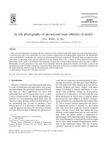
linity and the purity of obtained materials, PXRD for non-deposited
powder MOF-74 (Fig. 1, left column) and GIXRD for MOF-74 depos
ited on FeCrAl plates (Fig. 1, right column) were performed. In all pre
pared materials, as well as for the non-deposited crystal phase and thin
layer deposited on metallic carriers, the presence of Zn-MOF-74 (JCPDS
00-062-1198), Ni-MOF-74 (JCPDS 00-62-1029) and Co-MOF-74 (JCPDS
00-063-1147) structures without impurities [39,41,42] was confirmed.
The use of GIXRD analysis allowed high quality diffraction patterns on
MOF layers deposited on FeCrAl plates to be obtained. Despite the fact
that the GIXRD measurement was performed at a low angle, we could
still observe reflections at 25.6, 35.1, 37.8, 43.5, 52.6 (024) and 57.6� ,
which are characteristic of α-Al2O3 [43] (JCPD 04-005-4503) from
FeCrAl support. The α-Al2O3 is the result of the FeCrAl support calci
nation at 1100 � C which enhances the adhesion of deposited MOF layers.
The detailed phase analysis was previously reported in our previous
paper [44] and also in GIXRD profile analysis in supporting information
(Figs. S1-S2). It may be seen that the intensity of characteristic α-Al2O3
reflections decreases in the Co-MOF-74 >Ni-MOF-74> Zn-MOF-74
order, which may suggest that the thickness of metal organic frame
work layers in prepared structured catalysts increases. It is also worth
mentioning that, in all considered materials, we observed that the
crystallisation of MOF material over the metallic support was strongly
influenced by the number of metallic supports placed in the Teflon liners
for in situ deposition. Once the total amount of metallic supports
exceeded 1 g per synthesis, we did not observe the metal organic
framework crystals either in reacting vessels or deposited on the struc
tured carriers.
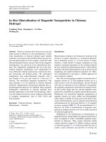
To determine the structure and the purity of the MOF layers depos
ited on FeCrAl plates, the XPS analysis of triple deposited MOF-74 layers
on FeCrAl plates was performed. The results of the XPS analyses are
presented in Fig. 2. The survey spectra of the triple deposited MOF-74
layers deposited on FeCrAl plates (black lines) and calcined FeCrAl
plates are presented in Fig. 2 A, D, G. It may be seen that the survey
spectra of Zn-MOF-74, Ni-MOF-74 and Co-MOF-74 do not reveal any
lines originating from calcined FeCrAl plates (cf. red lines) and only
signals from Me(Zn, Ni, Co) 2p, O1s and C1s may be observed. Since the
alumina is mainly present at the calcined FeCrAl plate surface due to the
migration of alumina at 1100 � C calcination, we used the signal at 75 eV
originating from Al 2p [45] as an internal marker to determine the pu
rity deposited MOF-74 layers. The zoomed area for 75 eV region for Me
(Zn, Ni, Co)-MOF-74 catalysts are presented in Fig. 2 B, E, H. It may be
seen that, for all considered cases, the Al 2p line does not occur at the
XPS spectra of Me (Zn, Ni, Co)-MOF-74 catalysts. The XPS spectra for Zn
2p, Ni 2p and Co 2p for Me (Zn, Ni, Co)-MOF-74 are presented in Fig. 2
C, F, I. The Zn-MOF-74/FeCrAl catalyst reveal two main peaks at 1022.2
and 1045.3 eV (Fig. 2 C) that may be attributed to Zn 2p3/2 and Zn 2p1/2
[46]. For the Ni-MOF-74/FeCrAl catalyst two main group bands were
detected with the peaks at 855.9 and 873.6 eV and associating satellite
peaks at 860.7 and 879.4 eV, which may be attributed to Ni 2p3/2 and Ni
2p1/2 [47], respectively. At the XPS spectrum of Co-MOF-74/FeCrAl,
catalyst peaks at 781.9 and 797.8 eV and associating satellite peaks at
785.8 and 802.6 eV are observed. These may be attributed to Co 2p3/2
and Co 2p1/2 [48], respectively.
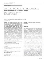
The effectiveness of the in situ MOF deposition over structured sup
ports was determined gravimetrically after each deposition. The results
are presented in Fig. 3 A. The effectiveness of the MOF deposition on the
structured carriers was presented as a mass increase per geometrical
surface area of metallic support. Such deposition results are commonly
used for the comparison of coating loading in structured reactors engi
neering [27,49]. The lowest MOF loading was observed for the layers
Fig. 1. XRD analysis of prepared materials; Left column: M(M ¼ Zn; Ni; Co)-MOF-74 powders; right column: GIXRD of M(M ¼ Zn; Ni; Co)-MOF-74 triple deposited
FeCrAl supports.
5
P.J. Jodłowski et al.
Microporous and Mesoporous Materials 303 (2020) 110249
Fig. 2. XPS analysis of prepared of triple deposited M(M ¼ Zn; Ni; Co)-MOF-74 on FeCrAl plates; Zn- MOF-74 (A–C): A) Zn-MOF-74 survey spectrum, B) Al 2p
marker region for Zn-MOF-74, C) Zn 2p region for Zn-MOF-74; Ni-MOF-74 (D–F): D) Ni-MOF-74 survey spectrum, E) Al 2p marker region for Ni-MOF-74, F) Ni 2p
region for Ni-MOF-74; Co-MOF-74 (G–I): G) Co-MOF-74 survey spectrum, H) Al 2p marker region for Co-MOF-74, I) Co 2p region for Co-MOF-74.
Fig. 3. A) M(M ¼ Zn; Ni; Co)-MOF-74 mass increase/geometrical surface of metallic carrier per deposition; B) Mechanical stability test in ultrasound bath.
deposited on FeCrAl plates. For this support, the individual deposition of
Zn- and Co-MOF-74 layers never exceeds 0.32 mg/cm2 (maximum value
achieved for Zn-MOF-74 after double deposition). The maximum mass
increase after triple deposition was achieved for Co-MOF-74, and was
equal to 0.669 mg/cm2. The deposition of MOF layers of on FeCrAl wire
gauze results in considerable MOF mass increase on metallic support. In
general, the MOF loading on wire gauze increases on average by a factor
of two, with some minor derogations for Co-MOF-74 at single deposition
where this value increases almost four-fold, and for Zn-MOF-74 at triple
loading, where the mass increase is almost one order of magnitude
higher than for the FeCrAl plate. When considering the total mass in
crease on the FeCrAl wire gauze in comparison with the FeCrAl plate,
the mass loading factor increases in a arrange 2.9-fold for Zn-MOF-74,
two-fold for Co-MOF-74 and up to 2.1 times for Ni-MOF-74 (cf.
Table S1). The highest metal organic metal loading by in situ deposition
was achieved for NiCr foam. Analysis of the obtained MOF loading
values (Table S1) reveals that the maximum MOF loading was achieved
after triple deposition of Co-MOF-74. Considerable high values were
achieved for double deposition of Zn-MOF-74. It must be emphasised
that the total mass increase forms the following order
Co-MOF-74>Zn-MOF-74>Ni-MOF-74, which is similar to MOF loading
on the FeCrAl plate and wire gauze. It must be also pointed out that the
Ni-MOF-74 indicated the worst adhesion properties on all considered
metallic carriers.
The morphology of deposited coatings on structured supports was
determined using two methods: digital photography and SEM micro
scopy. The results of digital photography imaging are presented in
supplementary materials in Figs. S3–S5 for Me (Zn, Ni, Co)-MOF-74
layers deposited on FeCrAl plates, FeCrAl wire gauzes and NiCr foams,
respectively. In the case of Zn-MOF-74, the single deposition on each
structured support is barely seen in digital pictures. Considerable
changes in layer deposition on each structured support may be observed
6
P.J. Jodłowski et al.
Microporous and Mesoporous Materials 303 (2020) 110249
after double and triple deposition (Figures S3-S5, B and C). For Ni and
Co-MOF-74 layers, the single deposition of MOF material may be
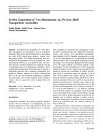
observed. To determine in detail the morphology of prepared structured
catalysts, SEM analysis was performed. To enhance the visibility of SEM
images, pseudo colouring by using defined RGB colours determined by
UV–Vis spectroscopy was performed. The SEM images are presented in
Fig. 4 for three structured carriers, and in Fig. 5 for triple deposited MOF
layer on NiCr foams with 2000x magnification. Since the whole matrix
contained 27 images per single SEM magnification, the results for each
deposition for M(M ¼ Zn; Ni; Co)-MOF-74 are presented in supple
mentary materials in Figs. S6–S14. The deposition of Zn-MOF-74 on
structured carriers is presented in Figs. S6-S8. It can be seen that, after
single deposition, surfaces of all three structured carriers at the lowest
magnification (200x) do not show any substantial changes in carrier
morphology. This changes upon increasing magnification from 2000x
up to 5000x. The surface seems to be coated with a thin layer of MOF
with visible small crystals of irregular shape. This phenomenon changes
after double in situ coating (Fig. S7). In this case, even a quick look at the
catalyst’s surface at low-magnification images reveals the complete
coverage of the structured carrier. The crystals began to grow in more
regular shape, similar to hexagonal rods. The shape of the Zn-MOF-74
structures is more evident for wire gauze and foam structures. The
MOF-74 growth on structures is evident, and good adhesion may be
observed. The higher magnifications also reveal smaller crystals found
on larger ones (Figure S6-S8 E-F). The triple deposition reveals full
surface coverage in all three structured carriers. The MOF crystals reveal
full developed shapes. Detailed analysis of SEM images allows the
thickness of the Zn-MOF-74 layers to be determined, which in that case
is equal to 40 μm. The important feature of Zn-MOF-74 layers is depicted
in Fig. 4 A1, B1, C1 as well as in Figs. S6–S8 G-I, where, for the foam
carrier, the MOF crystals are perpendicularly oriented to the foam sur
face, in contrast to the FeCrAl plates and wire gauzes, where the sto
chastic orientation prevails.
The SEM images for Ni-MOF-74 are presented in Fig. 4 A2, B2, C2 for
triple deposition and in Figs. S9–S11 for single, double and triple
deposition. It may be seen that the crystal morphology is far different
from that of Zn-MOF-74 crystals. The surfaces of all three structured
carriers are covered with spherical crystals with an average diameter of
10 μm. However, it must be emphasised that the crystals form a thin
layer which is more visible after double and triple coating of wire gauze
and foam carriers. One can observe that surface coverage is uniform
after double deposition on structured carriers. After triple deposition,
the carriers’ surfaces reveal point-crystal growth (Fig. 4 B2 and C2). The
thickness of the Ni-MOF-74 layers was equal to the average MOF particle
diameter, i.e. 10 μm. The average thickness after triple coating was
approx. 30 μm (cf. Fig. S11 G).
The Co-MOF-74 morphology is presented in Fig. 4 A3, B3, C3 and
Figs. S12–S14. The crystal morphology exhibits more regular hexagonal
shape in comparison with Zn-MOF-74. It can be seen that complete
carrier coverage is achieved after single deposition in all considered
carriers (Figures S12 A-I). It must be emphasised that, for single
deposited Co-MOF-74 on NiCr foam, there is different morphology in
Fig. 4. SEM images of M(M ¼ Zn; Ni; Co)-MOF-74 triple deposited on various metallic supports; A1, B1, C1) Zn-MOF-74, A2, B2, C2) Ni-MOF-74, A3, B3, C3) CoMOF-74; A) FeCrAl plates, B) FeCrAl wire gauzes, C) NiCr foams.
7
P.J. Jodłowski et al.
Microporous and Mesoporous Materials 303 (2020) 110249
Fig. 5. Magnified (x2k) SEM images of M(M ¼ Zn; Ni; Co)-MOF-74 triple deposited on metallic foam NiCr; A) Zn-MOF-74, B) Ni-MOF-74, C) Co-MOF-74.
comparison with Co-MOF-74 deposited on the FeCrAl plate and wire
gauze. The foam surface seems like it was treated by some kind of MOF
primer and forms the incubation-like centres for further crystal growth.
The morphology of the Co-MOF-74 crystals is similar for all kinds of
metal supports after single deposition (Figures S12 A-I). In all considered
structured carriers, the hexagonal crystal is perpendicularly oriented to
the metallic carriers. The triple deposition of Co-MOF-74, however,
causes crystal aggregation, and local crystal spots can be observed
especially for the FeCrAl wire gauze and NiCr foam. However, the
presence of the local crystal hypertrophies is not evident as in the case of
Zn- and Ni-MOF-74 layers. It must also be pointed out that the thickness
of the Co-MOF-74 layers is lower than for Ni-MOF-74 and is equal to 20
μm (average single crystal size). Due to the growth of the MOF crystals
perpendicular to the support surface, the crystal tends to fill the free
space between crystals rather than to overgrow already grown crystals.
The results of the krypton and nitrogen adsorption on bare structured
carriers, MOF powders and MOF deposited on metallic supports are
summarised in Table 3. The krypton adsorption on structured supports
revealed that structured carriers are non-porous solids (Table 3 A). The
measured SBET for the FeCrAl plate, wire gauzes and NiCr foams were
equal to 0.027, 0.012 and 0.039 m2/g, respectively. The nitrogen
adsorption on powder samples (Table 3 B), collected using the in situ
solvothermal method, revealed that the specific surface SBET areas of
prepared samples were approx. 1000 m2/g for all prepared powder
MOF-74 samples, which corresponds well with the results presented in
the literature [39,42]. Since for the characterisation of metallic struc
tured catalysts with deposited porous metal organic framework layers
there is no proposed methodology for the presentation of the SBET re
sults, the data presentation was two-fold. To compare the specific sur
face of the M(M ¼ Zn; Ni; Co)-MOF-74 layer over representative FeCrAl
support, the SBET was referred to the mass of MOF-74 deposited on the
metallic carrier. This value was determined gravimetrically after M(M ¼
Zn; Ni; Co)-MOF-74/FeCrAl plate activation. However, to compare the
values of the specific surface between the supported catalysts, the SBET
was referred to the total mass of the structured catalyst. When analysis of
SBET for the FeCrAl plate referred to the deposited MOF layer (Table 3 C),
it may be seen that the values for SBET are lower than the calculated
specific surface areas for powder samples, and are equal to 331.6 m2/g
for Zn-MOF-74, 823.5 m2/g for Ni-MOF-74 and 716.7 for m2/g for
Co-MOF-74. It may be observed that a considerable decrease was
observed for Zn-MOF-74, where the value of specific surface area was
approx. 700 m2/g lower than for its powder counterpart. The difference
between the calculated SBET values may be two-fold. The successful in
situ synthesis of Zn-MOF-74 over metallic structures was achieved by the
optimised triple synthesis, where the primer layer on Zn-MOF-74 was
prepared from the zinc acetate solution, whereas double and triple
deposition was synthesised by using a nitrate solution as zinc precursor.
For Ni- and Co-MOF-74 catalysts, the observed SBET decrease was lower
and equal to approx. 200 m2/g and 300 m2/g. In this case, however, the
Ni- and Co-MOF-74 the triple deposition may cause crystal overgrowth
Table 3
Results of the krypton and nitrogen adsorption for prepared samples; A) Kr adsorption results for metallic supports, B) N2 adsorption measurements for powder M(M ¼
Zn; Ni; Co)-MOF-74 samples, C) N2 adsorption measurements for triple deposited M(M ¼ Zn; Ni; Co)-MOF-74/FeCrAl referred to deposited MOF mass, D) N2 adsorption
measurements for triple deposited M(M ¼ Zn; Ni; Co)-MOF-74/FeCrAl referred to total mass of structured reactor.
A) Metallic supports
Kr adsorption measurement
B) Powder samples M(M ¼ Zn; Ni; Co)-MOF-74 powders
2
SBET, [m /g]
N2 adsorption measurement
FeCrAl plate
0.027
Zn-MOF-74
FeCrAl wire gauze
0.012
Ni-MOF-74
NiCr foam
0.039
Co-MOF-74
C) M(M ¼ Zn; Ni; Co)-MOF-74/FeCrAl (triple deposition) plate referred to deposited MOF mass
N2 adsorption measurement
SBET, [m2/g]
Zn-MOF-74
331.6
Ni-MOF-74
823.5
Co-MOF-74
716.7
D) Supported M(M ¼ Zn; Ni; Co)-MOF-74 (triple deposition) referred to total structured reactor mass
N2 adsorption measurement
Sample
SBET, structured reactorb, [m2/g]
FeCrAl plate
Zn-MOF-74
0.70
Co-MOF-74
26.95
Ni-MOF-74
22.60
FeCrAl wire gauzea
Zn-MOF-74
0.40
Co-MOF-74
11.30
Ni-MOF-74
8.30
NiCr foam
Zn-MOF-74
0.78
Co-MOF-74
65.88
Ni-MOF-74
45.80
a
b
Calculated by using eq. (1).
SBET, structured reactor related to the total mass of structured reactor.
8
SBET, [m2/g]
1023.7
1003.3
1021.5
Calculated mass of deposited MOF, [mg/g structured
0.80
26.40
22.50
0.40
11.30
9.60
0.80
46.9
65.7
ractor]
P.J. Jodłowski et al.
Microporous and Mesoporous Materials 303 (2020) 110249
Table 4
Results of catalytic activity of prepared samples in aerobic oxidation of cyclohexene.
MOF sample
Pressure
blank
blank
Zn-MOF-74
powder
Ni-MOF-74
/NiCr foam
powder
Co-MOF-74
/NiCr foam
powder
/NiCr foam
atm.
10 bar
atm.
10 bar
10 bar
atm.
10 bar
10 bar
atm.
10 bar
10 bar
Conversion [%]
12.0
10.0
66.5
64.8
30.2
59.0
81.7
34.1
52.3
67.9
29.1
Selectivity [%]
A
B
C
D
other
6.7
6.3
12.5
12.1
9.7
8.7
8.5
8.3
18.9
12.7
18.9
62.1
64.0
65.4
58.8
71.9
74.3
52.7
73.5
29.4
35.5
30.4
16.9
16.1
13.9
14.0
14.5
13.3
16.5
14.3
22.2
27.7
23.3
5.0
4.5
5.8
6.0
1.7
2.3
7.4
2.5
0.0
3.0
4.4
9.4
9.1
2.5
9.2
2.2
1.3
14.9
1.4
29.5
21.1
23.0
which may influence the overall SBET value. Additionally, the multiple
layer deposition may also influence the availability of micro and mes
opores for adsorbed molecule. Analysis of the SBET values referred to the
total mass of the structured catalyst (Table 3 D; mass of the metallic
carrier ỵ mass of the deposited layer) leads to the general conclusion
that the amount of the deposited metallic organic frameworks on the
structured support increases in the following order: FeCrAl wire gauze
> FeCrAl plate > NiCr foam, which is different than the gravimetrical
measurements from Table S1 and Fig. 3. However, it must be emphas
ised that the values determined by the gravimetrical method were per
formed after structure catalyst washing after in situ deposition and are
not impacted by the high temperature UHV activation of catalysts
samples in the sorption meter. Analysis of the literature data on TGA
analysis of the metal organic frameworks leads to the conclusion that, at
approx. 300 � C, M (M ¼ Zn; Ni; Co)-MOF-74 is equal to 30 wt %. of the
initial mass [39,40]. In this study, the activation of MOF prior to the N2
sorption was performed under 250 � C to ensure effective activation.
Since the metal supports used in this study are non-porous solids, we can
estimate the mass of the catalyst deposited on the surface of the struc
tured supports by formula previously proposed in the literature [50]:
m MOF deposited on
the support
¼
Me (Zn, Ni, Co) concentration in
post-reaction mixture, mM
–
–
0.12
3.03
0.39
Here, the total mass of deposited MOF calculated from N2 sorption gives
two-order of magnitude higher values of deposited MOF when
comparing to Zn-MOF-74. The SEM results clearly show the growth of
well-defined crystals on structured supports after single deposition
(Figs. S9-S11).
To determine the molecular nature of the prepared structured MOF
catalysts, IR and Raman analyses were performed. The detailed IR
analysis of prepared samples using ATR, DRIFT and transmission IR can
be found in supporting information (Fig. S15). The characterisation of
the active centres in prepared materials was performed by the sorption
of two probe molecules: carbon monoxide and CD3CN. Both probe
molecules are commonly used to study acidic and basic properties of
heterogeneous catalysts. The results of CO and CD3CN adsorption are
presented in Fig. 6 and Fig. 7, respectively. The low temperature of
carbon monoxide adsorption on M(M ¼ Zn; Ni; Co)-MOF-74 gives the
rise of the main band at 2160-2180 cm 1, which corresponds to Me2ỵCO adducts formed in the prepared metal organic framework catalysts.
It has been previously reported in the literature [51,52] that the values
of the main CO adsorption bands for M(M ¼ Zn; Ni; Co)-MOF-74 de
creases in the following order: Ni (2180 cmÀ 1) > Zn (2173 cmÀ 1) > Co
(2162 cmÀ 1). The high C–O stretching frequencies are derivative of the
smallest size and the highest polarisation of Ni2ỵ ion for the Ni-MOF-74
sample (Fig. 6 B) [51,52]. It must be emphasised that, upon increase of
partial pressure of carbon monoxide, the minor bands at 2150-2100
cmÀ 1 and 2200-2250 cmÀ 1 can be observed and may be attributed to
some combination overtones of ν(CO). It was also observed that, at high
CO coverages, for Zn-MOF-74 and Ni-MOF-74 an additional band at
around 2135 cmÀ 1 is formed, which was previously assigned to liquified
CO in the MOF pores [53].
The results of CD3CN probe molecule adsorption on M(M ¼ Zn; Ni;
Co)-MOF-74 catalysts are presented in Fig. 7. The adsorption of CD3CN
probe molecules shows rise of a sharp and intensive band at 2110 cmÀ 1,
which is characteristic of deuterated ν(CD3) vibrations, and two intense
bands at 2237 and 2290 cmÀ 1, which may be attributed to physiosorbed
CD3CN and coordinated CN species to Lewis acid sites, respectively [53,
54]. The acidic properties of various MOF materials by using CD3CN as a
probe molecule has recently been reported for MIL-140C (Zr), MIL-140D
(Zr) [55], MIL-100 (Al, Fe, Cr) [54]. It must be pointed out that the
values of ν(CD3) and ν(CN) vibrations are similar to those reported for
MIL 140C, D and MIL-100 metal organic frameworks, which may lead to
the conclusion that they possess similar acid strength.
The complementary experiments of molecular properties of prepared
samples were performed by μRaman spectroscopy. The results of
μRaman analysis were presented as a μRaman maps (Figs. 8 and 9), for
two reasons. The μRaman mapping allowed us to show the distribution
SBET; MOF deposited on the support
⋅ mMOF powder ⋅1000; ½mg�
SBET; MOF powder
(1)
where: mMOF deposited on the support is the approximated mass of the
deposited MOF layer on structured support, SBET, MOF deposited on the
support is the specific surface area of the structured reactor (structured
support with MOF layer), MOF powder is the mass of the powder used to
calculate SBET equal to 1 g. The calculated values of MOF mass deposited
on different structured supports lead to the conclusion that the MOF-74
layers are favourably deposited on NiCr foams and FeCrAl plates.
However, to fully characterise the effectiveness of the in situ layering,
the type of the MOF-74 by metal should be considered. It may be seen
that the lowest calculated MOF masses were obtained for Zn-MOF-74.
Despite the fact that, in the case of Zn-MOF-74, XRD analyses revealed
a characteristic pattern for MOF-74 crystals at the metallic support, deep
analysis of the SEM pictures for individual depositions shows that the
well-defined crystals are formed after triple deposition (Fig. 5 and
Figs. S6-S8). The first two layers should therefore be defined as inter
mediate MOF-layers or primer MOF-layers. The decrease in calculated
MOF referred to the total mass of the structured catalysts using N2
sorption is related to the low contribution of well-crystallised MOF on
the overall mass of the deposited layer. The opposite situation can be
observed for Ni- and Co-MOF-74 layers deposited on structured carriers.
9
P.J. Jodłowski et al.
Microporous and Mesoporous Materials 303 (2020) 110249
Fig. 6. In situ FTIR spectra of CO adsorbed at À 100 � C, A) Zn-MOF-74, B) Ni-MOF-74, C) Co-MOF-74.
Fig. 7. In situ FTIR spectra of CD3CN adsorbed at RT, A) Zn-MOF-74, B) Ni-MOF-74, C) Co-MOF-74.
of the MOF over the metallic carrier. Comparison of the μRaman maps
leads to the conclusion that the most uniform distribution was achieved
for Ni and Co-MOF-74 samples (Fig. 8 C and D). Indeed, the μRaman
maps also exhibit local layer overlapping (brighter spots at μRaman
maps), which is in good agreement with SEM images for samples after
MOF triple deposition. However, it must also be pointed out that the
determination of the surface homogeneity using only μRaman maps
must be carried out with a high degree of caution, since μRaman maps
for the homogeneous calcined FeCrAl plate also reveal some local in
crease in Raman intensity. The corresponding Raman spectra (Fig. 9)
exhibit the structure of prepared composite samples. The Raman spec
trum of the calcined FeCrAl plate (Fig. 9 A) reveals bands at 418, 630
and 750 cmÀ 1, which may be attributed to α-Al2O3 of hexagonal sym
metry (band at 418 cmÀ 1) [56], α-Fe2O3 (band 630) and γ-Fe2O3 [57].
The μRaman of the FeCrAl plate may be treated as a marker. Since the
depth of the sample penetration is relatively high for Raman scattering,
the presence or absence of a marker band may be useful in determining
the surface thickness. In our previous work, we reported that the use of
various characterisation techniques such as XPS, μRaman and EDX al
lows the determination of the in-depth distribution of the active phase
[58]. Here, we can observe that, for the M(M ¼ Zn; Ni; Co)-MOF-74
composite catalysts deposited on metallic support, there was no signal
originating from the metallic support. The Raman spectra of M(M ¼ Zn;
Ni; Co)-MOF-74 reveal two main band group regions: to 820 cmÀ 1 and
1200-1700 cmÀ 1. The 1200-1700 cmÀ 1 reveals bands at 1275, 1412,
1501, 1560 and 1619 cmÀ 1, which may be attributed to ν(C–O) from
deprotonated hydroxyls, symmetric ν(COOÀ ) and stretching and defor
mation vibrations of benzene rings [41], respectively. The bands at
lower frequencies, at approx. 820 and 560 cmÀ 1, may originate from
benzene ring bending and deformation vibrations, respectively [41,51].
The additional bands, at approx. 413 cmÀ 1, can be due to ν(Me–O) vi
brations [51]. Comparison of the Raman maps for M(M ¼ Zn; Ni;
Co)-MOF-74 structured catalysts and the FeCrAl plate lead to the
conclusion that the metallic carrier is uniformly covered with the MOF
layer. Similar observations can be observed from the analysis of XPS
results (cf. Fig. 2 A).
The adherence of the deposited on metallic support M(M ¼ Zn; Ni;
Co)-MOF-74 layers was evaluated by using an ultrasound bath me
chanical resistance test. This type of examination is frequently used for
layer adherence testing in structured catalyst characterisation [37,59,
60]. The results of the MOF layer adherence performance for various
structured supports are presented in Fig. 3 B. The results are presented as
a percentage of mass loss during ultrasonic irradiation treatment. The
best adherence properties were observed for NiCr foams. After the ul
trasonic irradiation test for Zn-MOF-74, almost 50% of the deposited
material remained at the support surface. This value was slightly lower
for the Ni and Co-MOF-74 layer, with 40% and 35% of the material
deposited over a metallic foam. The metal organic framework layers
deposited on FeCrAl wire gauzes indicated lower adherence to the
structured support. In the case of Zn-MOF-74, almost all of the deposited
material was removed from the structured support, whereas, for Ni and
Co-MOF-74, 10% and 20% of the deposited material remained on the
support. Comparison of the layer adherence to the support carrier after
mechanical resistance testing for FeCrAl plates and NiCr foams leads to
the conclusion that the stability of the deposited MOF material is de
rivative either of the available geometrical area and its shape or of the
total volume of the support which is sonochemically treated. During the
mechanical stability experiment, the structures were stochastically
placed in an ultrasonic bath. Their natural arrangement in the bath left
one of the sides less subjected to ultrasounds. What is more, comparison
of the support structure morphology for wire gauzes and foams may lead
to the conclusion that intensity of ultrasound waves can be gradually
screened by the bone-like structure of NiCr foam. It must be emphasised
that the literature reports on the deposition of metal organic frameworks
10
P.J. Jodłowski et al.
Microporous and Mesoporous Materials 303 (2020) 110249
Fig. 8. μRaman maps of M(M ¼ Zn; Ni; Co)-MOF-74 triple deposited on metallic plates, A) calcined metallic plate, B) Zn-MOF-74, C) Ni-MOF-74, D) Co-MOF-74.
on metallic supports is rather scarce, which makes comparison of the
obtained results with other literature reports impossible. Since the metal
organic frameworks are mainly formed into the desired shapes, such as
pellets, foams or monoliths with the addition of a binder [17–19], or as
required in the case of their use as the electrodes [13], the influence of
the other kinds of forces of the prepared materials has been considered.
The catalytic activity of prepared M(M ¼ Zn; Ni; Co)-MOF-74 pow
ders and Me (Zn, Ni, Co)-MOF-74 deposited on NiCr foams was
measured in the aerobic oxidation of cyclohexene. The results are
summarised in Table 4. It must be emphasised that bare metallic sup
ports revealed no activity in the aerobic activation oxidation of cyclo
hexene. The result of catalytic activity is expressed as a function of total
conversion of cyclohexene and individual selectivity to the main prod
ucts: cyclohexene oxide, 2-cyclohexen-1-ol, 2-cyclohexen-1-one and
trans-cyclohexane-1,2-diol. It may be seen that the activity of all pre
pared powder catalysts exceeds 50% conversion. The activity of pre
pared powder samples was: 66.5% for Zn-MOF-74, 59.0% for NiMOF-74
and 52.3% for Co-MOF-74 catalysts. Analysis of the selectivity for pre
pared samples shows that, for Zn- and Ni-MOF-74 catalysts, the oxida
tion reaction proceeds mainly to 2-cyclohexen-1-ol and 2-cyclohexen-1one. In the case of the Zn-MOF-74 catalyst, the selectivity to
cyclohexene-1-ol and 2-cyclohexen-1-one was 65.4% and 13.9%,
whereas for Ni-MOF-74 it was 74.3% and 13.3% respectively. The
selectivity for the cyclohexane oxide was 12.5 and 8.7% for Zn-MOF-74
and Ni-MOF-74, respectively. However, when analysing the oxidation
reaction results for Co-MOF-74, it may be seen that the cobalt oxide
favours the epoxidation reaction, with cyclohexane oxide as the main
product with almost 19% selectivity, whereas the contributions of the 2cyclohexen-1-ol, 2-cyclohexen-1-one and the other products were lower.
Moreover, among the products, trans-cyclohexane-1,2-diol was not
detected. Additionally, the contribution of the side products reached
30%. Although in the literature [29,61] we can find some results on
cyclohexene catalytic oxidation over Me-MOF-74 catalysts, comparison
of the obtained results is impossible due to different synthesis proced
ures for MOF-based materials and their different physicochemical
properties. For example, Ruano et al. [61] synthesised the catalysts from
metal acetate solutions (Zn, Co, Ni, Mn and Cu)-MOF-4 with another
nanocrystalline structure. Furthermore, the morphology of prepared
MOFs in Ref. [61] was far from that of our materials. The SBET values
presented in Refs. [61] were 948, 693 and 514 m2/g for Zn-, Co- and
Ni-MOF-74, respectively. These SBET results are considerably lower than
the SBET values presented in this work. The next difference between our
work and [61] lies in the fact that, during the catalytic activity tests,
Ruano et al. [61] used H2O2 or tetr-buty hydroperoxide (TBHP) as an
11
P.J. Jodłowski et al.
Microporous and Mesoporous Materials 303 (2020) 110249
reason of this phenomenon can be explained by the decrease of the
effectiveness factor of the catalyst in cyclohexene oxidation. Despite the
fact that in all catalytic experiments the same catalyst amount was used
(50.0 mg), it must be pointed out that, in the case of powder catalysts,
the availability of the active sites is higher due to the wide distribution of
catalysts in the reacting mixture. The comparison of the SEM results in
Figs. S6-S14 for both supported catalysts and powder MOF-based ma
terials shows that the size of the individual grains varies from 5 to 10 μm,
whereas the thickness of the deposited layer is as high as 40 μm. The
considerable thickness of the MOF layer on the support may lead to a
considerable decrease in the catalytic activity of prepared materials
according to the Thiele modulus. However, the calculation of the Thiele
modulus and effectiveness factor calculations exceeds the scope of this
article, indicating future directions for the application of structured re
actors with deposited MOFs.
The characterisation of MOF materials in the catalytic oxidation of
cyclohexene should consider also a factor related with the migration of a
metal from MOF structure to the reaction solution. The results of the
metal content in post-reaction mixtures are presented in Table 4.
Analysis of the obtained results leads to the conclusion that, in the case
of Zn-MOF-74 and Ni-MOF-74, the metal content in the post-reaction
mixture was below the detection limit. Only small amounts of zinc
ions were detected in the post-reaction mixture (0.12 mM). Noticeable
amounts of metal in the post-reaction mixture were observed for CoMOF-74. The amount to detected cobalt was approx. 3 mmol for the
Co-MOF-74 powder sample for the oxidation reaction under atmo
spheric and 10 bar O2 pressure. However, for MOF deposited on NiCr,
the value of detected Co was one order of magnitude lower, and was
equal to 0.39. The decrease of cobalt migration to the reaction mixture
may be related with the generally lower activity of the Co-MOF-74/NiCr
catalyst and the good adhesion of the MOF to the NiCr foam surface. It
must be emphasised that, in the case of MOF catalysts deposited on NiCr
foams, the catalysts were placed in the reaction vessel and simply
removed after the reaction, whereas cobalt catalysts in powder form
required additional filtration to separate the reacting mixture and
powder catalyst. The lack of additional filtration of the post-reaction
mixture and catalyst in the case of MOF deposited on NiCr may be a
fundamental step towards the wider application of MOF materials as
heterogeneous catalysts.
Fig. 9. μRaman spectra to μRaman maps of M(M ¼ Zn; Ni; Co)-MOF-74 triple
deposited on FeCrAl metallic plates; A) Zn-MOF-74, B) Ni-MOF-74, C) CoMOF-74.
oxidising agent together with atmospheric oxygen. Indeed, both oxi
dising agents can be used to either initialise radical reaction (TBHP) or
oxidise cyclohexene, but the oxidising effect is supposed to be higher
than in the case of molecular oxygen. Despite this fact, the authors
presented cyclohexene conversion reaching 71.5% for Co-MOF-74, 40%
for Ni-MOF-74 and 5% for Zn-MOF-74, and analysis of the reaction
product was performed by gas chromatography equipped with flame
ionisation detector. In relation to the work written by Sun et al. [29], the
preparation results were different from the preparation conditions pre
sented in this study.
When analysing the oxidation results under 10 bar O2 pressure, a
general increase of the activity for Ni- and Co-MOF-74 samples can be
observed. The conversion of cyclohexene for Ni-MOF-74 increases up to
81.7%, whereas for Co-MOF-74 the conversion is equal to 67.9%. The
individual selectivity for the oxidation products changes for Ni-MOF-74
at 10 bar O2, with considerable increase to 2-cyclohexen-1-one,
cyclohexane-1,2-diol and other products. In the case of Co-MOF-74,
with the reaction at elevated O2 pressure, the selectivity of oxidation
products remains at the same level, with a slight increase of selectivity to
cyclohexane-1,2-diol. For Zn-MOF-74 powder catalysts, we could see no
considerable changes in either conversion or selectivity. Catalytic ac
tivity was also determined for MOF catalysts deposited in situ on NiCr
foams. Through analysis of the results of the catalytic activity under 10
bar O2 pressure over structured M(M ¼ Zn; Ni; Co)-MOF-74 deposited on
NiCr foams, a general decrease in conversion of cyclohexene can be
observed. It can be seen that, in all considered MOFs deposited on NiCr
foams, the conversion of cyclohexene decreased by a factor of two. The
4. Conclusions
The aim of this paper was to obtain and characterise thin metal
organic framework layers on various metallic structured supports by
using spectroscopic and microscopic methods, and to determine their
potential application in the catalytic oxidation of cyclohexene. The in
situ deposition of metallic organic framework thin layers consists of
three steps, including support pre-treatment, in situ solvothermal
deposition and MOF-layer activation to remove residual solvents from
synthesis protocol. The prepared structured carriers with deposited
MOF-74 layers were characterised with various characterisation tech
niques to determine the surface morphology and their molecular struc
ture. The in situ deposition of metal organic frameworks was the most
effective for Zn- and Co-MOF-74 on NiCr foams, giving the approx. 4
mg/cm2 mass increase after triple coating. We have indicated that there
is no difference in molecular structure between in situ deposited and
non-deposited crystalline phase of metal organic frameworks. The high
mechanical resistance of prepared M(M ¼ Zn; Ni; Co)-MOF-74 layers on
NiCr foams and FeCrAl plates was confirmed by the ultrasonic irradia
tion performance.
The activity of prepared MOF catalysts both in powder form and
MOF deposited on NiCr foams was measured in the catalytic oxidation of
cyclohexene. The prepared catalysts revealed high activity in the studied
reaction, with the conversion exceeding 50% for powder catalysts under
both atmospheric and elevated pressures. The catalysts deposited on
NiCr foams revealed twice lower conversion in comparison with their
12
P.J. Jodłowski et al.
Microporous and Mesoporous Materials 303 (2020) 110249
powder counterparts. However, the use of structured catalysts did not
require their additional filtration from the reaction mixture, which
makes them favourable for further testing as heterogeneous catalysts in
the organic reagents oxidation.
We believe that the in situ deposition of metal organic frameworks
from Me2(dobdc) group, proposed in this study, will lead to the sub
stantial development of MOF materials and their further application in
heterogeneous catalysis as structured reactors.
[10] K. Leus, Y. Liu, P. Van Der Voort, Metal-Organic Frameworks as selective or chiral
oxidation catalysts, Catal. Rev. - Sci. Eng. 56 (2017) 1–56, />10.1080/01614940.2014.864145.
[11] R.M. Heck, S. Gulati, R.J. Farrauto, The application of monoliths for gas phase
catalytic reactions, Chem. Eng. J. 82 (2001) 149–156, />S1385-8947(00)00365-X.
[12] Z.G. Gu, J. Zhang, Epitaxial growth and applications of oriented metal–organic
framework thin films, Coord. Chem. Rev. 378 (2019) 513–532, />10.1016/j.ccr.2017.09.028.
[13] Z. Jiang, T. Liu, L. Yan, J. Liu, F. Dong, M. Ling, et al., Metal-organic framework
nanosheets-guided uniform lithium deposition for metallic lithium batteries,
Energy Storage Mater. 11 (2018) 267–273, />ensm.2017.11.003.
[14] X. Ma, Y. Chai, P. Li, B. Wang, Metal-organic framework films and their potential
applications in environmental pollution control, Acc. Chem. Res. 52 (2019)
1461–1470, />[15] A. Knebel, P. Wulfert-Holzmann, S. Friebe, J. Pavel, I. Strauß, A. Mundstock, et al.,
Hierarchical nanostructures of metal-organic frameworks applied in gas separating
ZIF-8-on-ZIF-67 membranes, Chem. Eur J. 24 (2018) 5728–5733, />10.1002/chem.201705562.
[16] J.L. Zhuang, D. Ar, X.J. Yu, J.X. Liu, A. Terfort, Patterned deposition of metalorganic frameworks onto plastic, paper, and textile substrates by inkjet printing of
a precursor solution, Adv. Mater. 25 (2013) 4631–4635, />adma.201301626.
[17] B. Valizadeh, T.N. Nguyen, K.C. Stylianou, Shape engineering of metal–organic
frameworks, Polyhedron 145 (2018) 1–15, />poly.2018.01.004.
[18] Y. Chen, X. Huang, S. Zhang, S. Li, S. Cao, X. Pei, et al., Shaping of metal-organic
frameworks: from fluid to shaped bodies and robust foams, J. Am. Chem. Soc. 138
(2016) 10810–10813, />[19] A. Garai, W. Shepherd, J. Huo, D. Bradshaw, Biomineral-inspired growth of metalorganic frameworks in gelatin hydrogel matrices, J. Mater. Chem. B. 1 (2013)
3678–3684, />[20] X. Wang, H. Xue, Z. Na, D. Yin, Q. Li, C. Wang, et al., Metal organic frameworks
route to prepare two-dimensional porous zinc-cobalt oxide plates as anode
materials for lithium-ion batteries, J. Power Sources 396 (2018) 659–666, https://
doi.org/10.1016/j.jpowsour.2018.06.086.
[21] N.V. Maksimchuk, K.A. Kovalenko, V.P. Fedin, O.A. Kholdeeva, Cyclohexane
selective oxidation over metal-organic frameworks of MIL-101 family: superior
catalytic activity and selectivity, Chem. Commun. 48 (2012) 6812–6814, https://
doi.org/10.1039/c2cc31877f.
[22] I.M. Denekamp, M. Antens, T.K. Slot, G. Rothenberg, Selective catalytic oxidation
of cyclohexene with molecular oxygen: radical versus nonradical pathways,
ChemCatChem 10 (2018) 1035–1041, />[23] Y. Cao, H. Yu, F. Peng, H. Wang, Selective allylic oxidation of cyclohexene
catalyzed by nitrogen-doped carbon nanotubes, ACS Catal. 4 (2014) 1617–1625,
/>[24] M. Kohantorabi, M.R. Gholami, Cyclohexene oxidation catalyzed by flower-like
core-shell Fe3O4@Au/metal organic frameworks nanocomposite, Mater. Chem.
Phys. 213 (2018) 472–481, />[25] A.L. Koritzke, J.C. Davis, R.L. Caravan, M.G. Christianson, D.L. Osborn, C.
A. Taatjes, et al., QOOH-mediated reactions in cyclohexene oxidation, Proc.
Combust. Inst. 37 (2019) 323–335, />[26] Y. Xue, W. Sun, Q. Wang, L. Cao, J. Yang, Sparsely loaded Pt/MIL-96(Al) MOFs
catalyst with enhanced activity for H2-SCR in a gas diffusion reactor under 80 � C,
Chem. Eng. J. 335 (2018) 612–620, />[27] A. Cybulski, J.A. Moulijn, Structured Catalysts and Reactors, CRC Press, 2005. htt
ps://books.google.pl/books?id¼r56LOldJ_N4C.
[28] V.K. Ambili, Studies on Catalysis by Ordered Mesoporous SBA-15 Materials
Modified with Transition Metals, Cochin University of Science and Technology,
2011.
[29] D. Sun, F. Sun, X. Deng, Z. Li, Mixed-metal strategy on metal-organic frameworks
(MOFs) for functionalities expansion: Co substitution induces aerobic oxidation of
cyclohexene over inactive Ni-MOF-74, Inorg. Chem. 54 (2015) 8639–8643,
/>[30] L. Giani, C. Cristiani, G. Groppi, E. Tronconi, Washcoating method for Pd/γ-Al2O3
deposition on metallic foams, Appl. Catal. B Environ. 62 (2006) 121–131, https://
doi.org/10.1016/j.apcatb.2005.07.003.
[31] J. Campbell, B. Tokay, Controlling the size and shape of Mg-MOF-74 crystals to
optimise film synthesis on alumina substrates, Microporous Mesoporous Mater.
251 (2017) 190–199, />[32] J.L.C. Rowsell, O.M. Yaghi, Effects of functionalization, catenation, and variation
of the metal oxide and organic linking units on the low-pressure hydrogen
adsorption properties of metal-organic frameworks, J. Am. Chem. Soc. 128 (2006)
1304–1315, />[33] J. Ma, A.P. Kalenak, A.G. Wong-Foy, A.J. Matzger, Rapid guest exchange and ultralow surface tension solvents optimize metal–organic framework activation, Angew.
Chem. Int. Ed. 56 (2017) 14618–14621, />[34] F. Yin, S. Ji, B. Chen, Z. Zhou, H. Liu, C. Li, Catalytic combustion of methane over
� x La x O 2 A
� x/2/Al 2 O 3/FeCrAl catalysts 310 (2006) 164–173, https://
Ce 1 A
doi.org/10.1016/j.apcata.2006.05.034.
[35] S. Zhao, J. Zhang, D. Weng, X. Wu, A method to form well-adhered g -Al 2 O 3
layers on FeCrAl metallic supports 167 (2003) 97–105, />S0257-8972(02)00859-9.
Declaration of competing interest
The authors declare that they have no known competing financial
interests or personal relationships that could have appeared to influence
the work reported in this paper.
CRediT authorship contribution statement
P.J. Jodłowski: Formal analysis, Investigation, Data curation,
Writing - review & editing. G. Kurowski: Formal analysis, Investigation.
K. Dymek: Formal analysis, Investigation. R.J. Jędrzejczyk: Formal
� : Formal analysis, Investigation. Ł.
analysis, Investigation. P. Jelen
� ski: Formal analysis, Investigation. A. Gancarczyk: Formal
Kuterasin
analysis, Investigation. A. Węgrzynowicz: Formal analysis, Investiga
tion. T. Sawoszczuk: Formal analysis, Investigation. M. Sitarz: Formal
analysis.
Acknowledgments
The authors would like to acknowledge dr Jakub Marchewka (Fac
ulty of Materials Science and Ceramics, AGH University of Science and
Technology) for digital photography of prepared structured catalysts
and also Maciej Bik (Faculty of Materials Science and Ceramics, AGH
University of Science and Technology) for GIXRD profile fitting and
phase assignment.
Appendix A. Supplementary data
Supplementary data to this article can be found online at https://doi.
org/10.1016/j.micromeso.2020.110249.
References
[1] S.R. Batten, N.R. Champness, X.-M. Chen, J. Garcia-Martinez, S. Kitagawa,
€
L. Ohrstr€
om, et al., Terminology of metal–organic frameworks and coordination
polymers (IUPAC Recommendations 2013), Pure Appl. Chem. 85 (2013)
1715–1724, />[2] N. Stock, S. Biswas, Synthesis of metal-organic frameworks (MOFs): routes to
various MOF topologies, morphologies, and composites, Chem. Rev. 112 (2012)
933–969, />[3] Y. Mao, J. Li, W. Cao, Y. Ying, P. Hu, Y. Liu, et al., General incorporation of diverse
components inside metal-organic framework thin films at room temperature, Nat.
Commun. 5 (2014) 1–9, />[4] V.V. Butova, M.A. Soldatov, A.A. Guda, K.A. Lomachenko, C. Lamberti, Metalorganic frameworks: structure, properties, methods of synthesis and
characterization, Russ. Chem. Rev. 85 (2016) 280–307, />RCR4554.
[5] J. Liu, P.K. Thallapally, B.P. McGrail, D.R. Brown, J. Liu, Progress in adsorptionbased CO 2 capture by metal–organic frameworks, Chem. Soc. Rev. 41 (2012)
2308–2322, />[6] H. Furukawa, K.E. Cordova, M. O’Keeffe, O.M. Yaghi, The Chemistry and
applications of metal-organic frameworks, Science (2013) 341, 80-, http://science.
sciencemag.org/content/341/6149/1230444.abstract.
[7] G. Zhu, R. Graver, L. Emdadi, B. Liu, K.Y. Choi, D. Liu, Synthesis of zeolite@metalorganic framework core-shell particles as bifunctional catalysts, RSC Adv. 4 (2014)
30673–30676, />[8] R. Krishna, Methodologies for evaluation of metal-organic frameworks in
separation applications, RSC Adv. 5 (2015) 52269–52295, />10.1039/c5ra07830j.
[9] R. Krishna, Methodologies for evaluation of metal-organic frameworks in
separation applications, RSC Adv. 5 (2015) 52269–52295, />10.1039/c5ra07830j.
13
Microporous and Mesoporous Materials 303 (2020) 110249
P.J. Jodłowski et al.
[36] X. Wu, D. Weng, S. Zhao, W. Chen, Influence of an aluminized intermediate layer
on the adhesion of a g -Al 2 O 3 washcoat on, FeCrAl 190 (2005) 434–439, https://
doi.org/10.1016/j.surfcoat.2004.03.007.
[37] P.J. Jodłowski, D.K. Chlebda, R.J. Jędrzejczyk, A. Dziedzicka, Ł. Kuterasi�
nski,
M. Sitarz, Characterisation of well-adhered ZrO2 layers produced on structured
reactors using the sonochemical sol–gel method, Appl. Surf. Sci. 427 (2018)
563–574, />[38] M. Valentini, G. Groppi, C. Cristiani, M. Levi, E. Tronconi, P. Forzatti, The
deposition of γ-Al2O3layers on ceramic and metallic supports for the preparation
of structured catalysts, Catal. Today 69 (2001) 307–314, />S0920-5861(01)00383-2.
[39] A.K. Das, R.S. Vemuri, I. Kutnyakov, B.P. McGrail, R.K. Motkuri, An efficient
synthesis strategy for metal-organic frameworks: dry-gel synthesis of MOF-74
framework with high yield and improved performance, Sci. Rep. 6 (2016) 1–7,
/>[40] R. Zhang, C.-A. Tao, R. Chen, L. Wu, X. Zou, J. Wang, Ultrafast synthesis of Ni-MOF
in one minute by ball milling, Nanomaterials 8 (2018) 1067, />10.3390/nano8121067.
[41] F. Bonino, S. Chavan, J.G. Vitillo, E. Groppo, G. Agostini, C. Lamberti, et al., Local
structure of CPO-27-Ni metallorganic framework upon dehydration and
coordination of NO, Chem. Mater. 20 (2008) 4957–4968, />10.1021/cm800686k.
[42] L. Garzon-Tovar, A. Sarne-Sanchez, C. Carbonell, I. Imaz, D. Maspoch, Optimised
room temperature, water-based synthesis of CPO-27- M metal-organic frameworks
with high space-time yields, J. Mater. Chem. A. 3 (2015) 20819–20826, https://
doi.org/10.1039/x0xx00000x.
[43] S.D. Ponja, I.P. Parkin, C.J. Carmalt, Synthesis and material characterization of
amorphous and crystalline (α-) Al2O3: via aerosol assisted chemical vapour
deposition, RSC Adv. 6 (2016) 102956–102960, />c6ra24018f.
[44] J. Łojewska, A. Knapik, A. Kołodziej, P. Jodłowski, Far field combined AFM and
micro-Raman imaging for characterisation of surface of structured catalysts:
example of Pd doped CoOx catalysts on precalcined kanthal steel, Top. Catal. 56
(2013) 1088–1095, />[45] V. Demange, J.W. Anderegg, J. Ghanbaja, F. Machizaud, D.J. Sordelet, M. Besser,
et al., Surface oxidation of Al-Cr-Fe alloys characterized by X-ray photoelectron
spectroscopy, Appl. Surf. Sci. 173 (2001) 327–338, />S0169-4332(01)00011-3.
[46] Z. Zhang, Y. Xiao, M. Cui, J. Tang, Z. Fei, Q. Liu, et al., Modulating the basicity of
Zn-MOF-74 via cation exchange with calcium ions, Dalton Trans. 48 (2019)
14971–14974, />[47] M. Mukoyoshi, H. Kobayashi, K. Kusada, M. Hayashi, T. Yamada, M. Maesato, et
al., Hybrid materials of Ni NP@MOF prepared by a simple synthetic method,
Chem. Commun. 51 (2015) 12463–12466, />[48] C. Huang, R. Liu, W. Yang, Y. Li, J. Huang, H. Zhu, Enhanced catalytic activity of
MnCo-MOF-74 for highly selective aerobic oxidation of substituted toluene, Inorg.
Chem. Front. 5 (2018) 1923–1932, />
[49] I. Nova, A. Beretta, G. Groppi, L. Lietti, E. Tronconi, P. Forzatti, Monolithic
catalysts for NOx removal from stationary sources, in: A. Cybulski, J.A. Moulijn
(Eds.), Struct. Catal. React, CRC Press, 2005, pp. 171–214.
[50] E. Hędrzak, A. Węgrzynowicz, R. Rachwalik, B. Sulikowski, P. Michorczyk,
Monoliths with MFI zeolite layers prepared with the assistance of 3D printing:
characterization and performance in the gas phase isomerization of А-pinene,
Appl. Catal. A Gen. 579 (2019) 75–85, />apcata.2019.04.017.
[51] S. Chavan, F. Bonino, J.G. Vitillo, E. Groppo, C. Lamberti, P.D.C. Dietzel, et al.,
Response of CPO-27-Ni towards CO, N2 and C2H 4, Phys. Chem. Chem. Phys. 11
(2009) 9811–9822, />[52] S. Chavan, J.G. Vitillo, E. Groppo, F. Bonino, C. Lamberti, P.D.C. Dietzel, et al., CO
Adsorption on CPO-27-Ni Coordination Polymer : Spectroscopic Features and
Interaction Energy, (2009) 3292-3299.
[53] S. Bordiga, E. Escalona Platero, C. Otero Are�
an, C. Lamberti, A. Zecchina, Low
temperature CO adsorption on Na-ZSM-5 zeolites: an FTIR investigation, J. Catal.
137 (1992) 179–185, />[54] C. Volkringer, H. Leclerc, J.C. Lavalley, T. Loiseau, G. F�
erey, M. Daturi, et al.,
Infrared spectroscopy investigation of the acid sites in the metal-organic
framework aluminum trimesate MIL-100(Al), J. Phys. Chem. C 116 (2012)
5710–5719, />[55] F. Bonino, C. Lamberti, S. Bordiga, IR and Raman spectroscopies probing MOFs
structure, defectivity, and reactivity, Chem. Met. Fram. Synth. Charact. Appl.
(2016) 657–690, />[56] J. Łojewska, A. Knapik, P. Jodłowski, T. Łojewski, A. Kołodziej, Topography and
morphology of multicomponent catalytic materials based on Co, Ce and Pd oxides
deposited on metallic structured carriers studied by AFM/Raman interlaced
microscopes, Catal. Today 216 (2013) 11–17, />cattod.2013.05.008.
[57] R. Otero-Lorenzo, M.C. Weber, P.A. Thomas, J. Kreisel, V. Salgueiri~
no, Interplay of
chemical structure and magnetic order coupling at the interface between Cr2O3
and Fe3O4 in hybrid nanocomposites, Phys. Chem. Chem. Phys. 16 (2014)
22337–22342, />[58] P.J. Jodłowski, R.J. Jȩdrzejczyk, A. Rogulska, A. Wach, P. Ku�strowski, M. Sitarz, et
al., Spectroscopic characterization of Co3O4 catalyst doped with CeO2 and PdO for
methane catalytic combustion, Spectrochim. Acta - Part A Mol. Biomol. Spectrosc.
131 (2014) 696–701, />[59] V. Meille, S. Pallier, G.V. Santa Cruz Bustamante, M. Roumanie, J.P. Reymond,
Deposition of γ-Al2O3layers on structured supports for the design of new catalytic
reactors, Appl. Catal. A Gen. 286 (2005) 232–238, />apcata.2005.03.028.
[60] V. Meille, Review on methods to deposit catalysts on structured surfaces, Appl.
Catal. A Gen. 315 (2006) 1–17, />[61] D. Ruano, M. Díaz-García, A. Alfayate, M. S�
anchez-S�
anchez, Nanocrystalline MMOF-74 as heterogeneous catalysts in the oxidation of cyclohexene: correlation of
the activity and redox potential, ChemCatChem 7 (2015) 674–681, https://doi.
org/10.1002/cctc.201402927.
14