Wet-chemical porosification of LTCC substrates: Dissolution mechanism and mechanical properties
Bạn đang xem bản rút gọn của tài liệu. Xem và tải ngay bản đầy đủ của tài liệu tại đây (2.96 MB, 10 trang )
Microporous and Mesoporous Materials 288 (2019) 109593
Contents lists available at ScienceDirect
Microporous and Mesoporous Materials
journal homepage: www.elsevier.com/locate/micromeso
Wet-chemical porosification of LTCC substrates: Dissolution mechanism and
mechanical properties
T
Ali Hajiana,*, Martin Brehlb, Thomas Kochc, Christopher Zellnera, Sabine Schwarzd,
Thomas Koneggere, Dominique de Lignyc, Ulrich Schmida
a
Institute of Sensor and Actuator Systems, TU Wien, Gusshausstrasse 27-29, 1040, Vienna, Austria
Institute of Glass and Ceramics, University of Erlangen-Nuremberg, 91058, Erlangen, Germany
c
Institute of Materials Science and Technology, TU Wien, Getreidemarkt 9/308, 1060, Vienna, Austria
d
University Service Centre for Transmission Electron Microscopy, TU Wien, Wiedner Hauptstrasse 8-10, 1040, Vienna, Austria
e
Institute of Chemical Technologies and Analytics, TU Wien, Getreidemarkt 9/164-CT, 1060, Vienna, Austria
b
A B S T R A C T
Low temperature co-fired ceramics (LTCC) technology has been successfully used in microelectronics, automotive, and telecommunication applications. However,
their generally high permittivity is unfavorable for micromachined devices operated at high frequencies. To overcome this drawback, we have established a wetchemical etching process as an effective approach which can be applied to LTCC substrates in their as-fired state and allows for a local permittivity reduction in
regions of interest. Understanding the etching mechanism is essential for the selection of appropriate etching conditions to control the degree of porosification.
Therefore, in the present work, we report on an effective approach to achieve a tailored porosification of LTCC substrates. Different characterization techniques such
as scanning and transmission electron microscopy, energy-dispersive X-ray spectroscopy, X-ray diffraction analysis, and Raman Spectroscopy were used for investigation of the morphology and chemical composition of the substrates and thereby studying the etching mechanism. Furthermore, using dynamic-mechanical
analysis at temperatures up to 550 °C, the stiffness behavior of the LTCC substrates after wet-chemical etching was investigated, and promising results for the
applicability of such modified modules were obtained, even when operated at elevated temperatures up to 550 °C. Finally, a practical correlation between the
mechanical properties and the relative porosification depth is presented, which is independent of etching conditions and the substrate thickness, and is valuable for
optimization of the suitable depth of porosification for securing the desired mechanical properties.
1. Introduction
In recent years, Low-Temperature Co-fired Ceramics (LTCC) substrates which are advanced composites of glass and ceramics sintered at
temperatures below 1000 °C, have become an attractive technology for
the robust assembly and packaging of electronic components and microelectromechanical systems (MEMS) [1–3]. The low sintering temperature allows for co-firing of the LTCC with metals offering a high
electrical conductivity, such as Au, Ag, Cu, and their alloys (such as
Ag–Pt, Au–Pt, and Ag–Pd) which all have low melting points close to
1000 °C. Moreover, the applicability of the multilayer approach based
on glass-ceramics sheets not only facilitates their fabrication in the
“green state”, but also allows for the realization of compact 3D structures with highly scalable manufacturing methods (e.g., microfluidic
channels) as well as embedding passive electrical components such as
capacitors, resistors, inductors, and conductor lines into the LTCC body
[1,3–6]. Therefore, this technology is very attractive for a wide range of
applications including pressure [7,8], temperature-pressure [9,10],
robust flow sensors [11,12], temperature-pressure-humidity [13], pH
*
[14,15], gas [16,17], and electrochemical [18,19] sensors as well as
Pirani micro gauges [20], microfluidic systems [21–24] and lab-on-chip
(LOC) devices [25,26].
Due to its hermeticity, mechanical durability, attractive thermomechanical and dielectric properties, and also compatibility with thick
film hybrid technology, LTCC technology has attracted the most attention in wireless communication, and electronic control units.
Furthermore, there is particularly a major industrial interest in using
this technology for fabricating high-density multi-layer packages suitable for microwave applications and automotive electronics [27–30].
However, an integration of patch antennas and accurate design of
micromachined structures operating at high frequencies require separate regions of tailored permittivities for optimized radiation. While
areas with low permittivity enhance both the bandwidth and the efficiency of the active components, high permittivity areas allow a compact feeding circuit design. To achieve this goal, a possible strategy
could be combining polymer and LTCC substrates [31,32]. This approach entails inherent disadvantages associated with bond wires such
as parasitic inductances, expensive and complicated manufacturing
Corresponding author.
E-mail address: (A. Hajian).
/>Received 25 April 2019; Received in revised form 20 June 2019; Accepted 3 July 2019
Available online 04 July 2019
1387-1811/ © 2019 The Authors. Published by Elsevier Inc. This is an open access article under the CC BY license
( />
Microporous and Mesoporous Materials 288 (2019) 109593
A. Hajian, et al.
Material properties and detailed fabrication process of the Ferro L8 can
be found in the corresponding datasheet [45]. Phosphoric acid (H3PO4
85 wt%) from Sigma-Aldrich served as etching solution directly or after
dilution with deionized water. Sodium hydroxide (NaOH) pellets (99%
from VWR) were used for the preparation of alkaline etchants. All the
etching experiments were performed at constant temperatures in a
capped beaker with a polytetrafluoroethylene (PTFE) fixture for
holding the substrates in position. Through magnetic stirring of the
etchant at 120 rpm during the etching reaction, the effective exchange
of reactants and etching products was ensured. The etched LTCC substrates were washed with water and propane-2-ol and then dried at
110 °C before further analyses.
The phase composition of the as-fired LTCC substrate was explored
by Inductively Coupled Plasma Optical Emission Spectroscopy (ICPOES) measurements using a Spectro Genesis FES. Also, to acquire information about the dissolved phases and thereby of the etching mechanism, Raman spectra were recorded with a Thermo Scientific
Nicolet™ Almega spectrometer coupled with a high-quality Olympus
microscope and high-resolution grating. Laser excitation was done at a
wavelength of 532 nm, and the spot size was approximately 1 μm (using
a 50 × objective lens with 0.75 NA).
Weight loss of the samples due to the etching process was used as a
primary criterion for the degree of porosification. The gravimetrical
studies were carried out by using a Sartorius R200D microbalance with
a standard deviation of less than 0.02 mg. The depth of porosification
for the samples etched at different conditions was measured by applying the open software ImageJ, which is widely used in scientific
research [46,47], for cross-sectional images of the fracture planes obtained using a Hitachi SU8030 scanning electron microscope (SEM).
The SEM micrographs were acquired at an operating voltage of 2 kV in
the charge suppression scanning mode and without any pre-metal
coating of the specimens.
To evaluate the stiffness behavior of the Ferro L8 substrates due to
the etching process, dynamic-mechanical analysis (DMA) was carried in
bending mode in the temperature range from 25° to 550 °C using a TA
Instruments DMA Q800.
The span width was 10 mm, and the dynamic amplitude was 20 μm
in the case of the specimens with a thickness of 180 μm and 7 μm for the
520 μm thick samples. A frequency of 1 Hz and a ratio of static to dynamic force of 1.25 were applied. The temperature was increased
stepwise, starting at 25 °C, then ramped to 50 °C and from then the step
size was 50 °C. After a dwell time of 10 min at each temperature step,
the specimen was dynamically loaded for 30 s, and the storage modulus
(E′) was determined. E′ is the stress-to-strain ratio in a system having
sinusoidal loading and represents the energy storage capacity of a
system and other relevant properties of the elastic portion. Basically,
the quantity E’ is a measure of the stiffness of the material [48].
By using the ‘lift-out’ technique in a dual beam focused ion beam
(DBFIB) FEI Quanta 200 3D system, LTCC foils were fabricated and
used for the transmission electron microscope (TEM) imaging through
an FEI Tecnai F20 field-emission TEM (FE-TEM) operating at 200 kV.
Selected area electron diffraction (SAED) was used for analyzing crystalline and amorphous phases in the LTCC.
processes, as well as different coefficients of thermal expansion (CTE)
which result in local strain generation and thereby may lead to a reduced lifetime.
Another approach for reducing the permittivity is introducing air,
which possesses a very low permittivity (εr = 1), into the material.
Different pore formation methods, including freeze-dry processing [33],
extrusion [34], and use of pore-forming agents [35] have been reported
in previous studies. Modification with oxides of multivalent metals is
another method which affects the porous structure of ceramics due to
the filling of macropores [36]. However, all the mentioned methods
require alteration of the LTCC tape composition and hence, cannot be
straightforwardly integrated into well-established LTCC substrate fabrication processes.
These problems could be overcome by the development of a porosification technique which allows for a local permittivity reduction of
LTCC substrates. This method, which is based on replacing some of
high-k LTCC constituents with air through a wet-chemical etching
process, was first reported in Ref. [37]. By applying this method for the
commercial 951 LTCC tape from DuPont, a maximum porosification
depth (dp) of about 40 μm was achieved. Important information on the
porosification mechanism was obtained through further studies on the
wet-chemical etching of several LTCC tapes at different conditions
[38–41].
Since this technique can be applied to the LTCC substrate in the asfired state, no alteration in the tape chemical composition or firing
profile is necessary and therefore it is considered as a very cost-effective
and straightforward method for permittivity reduction. Moreover,
through precise masking of the substrate, areas of the different permittivity can be realized in one layer. The degree of permittivity reduction is directly related to the degree of porosification because by
increasing the latter parameter, more air is embedded into the LTCC
substrate, and therefore, the overall permittivity will be further decreased. Typically, the degree of porosification can be increased either
through the axial or lateral pore growth — the later most likely results
in wider pore openings and hence, a degraded surface quality.
However, a high-quality surface is crucial for high-frequency applications because with increasing frequency in the GHz range the skin
depth, derived for ideally smooth conductor surfaces, decreases to the
order of the surface roughness, thus causing a nearly linear increase in
conductor loss [42–44].
On the other hand, axial growth of the pores through deep penetration of the etching solution while preserving the surface quality
would meet both requirements with respect to the significant air embedment and the high-quality metallization. However, the porosification typically gives rise to channel-like, statistically distributed, and
interconnected open meso-to macropores, which deteriorate the mechanical strength of the LTCC. Therefore, deep porosification of the
LTCC could result in a reduction of the mechanical substrate stability
and consequently in a reduced lifetime.
The present work aims towards a comprehensive study on the
etching process of a commercially available LTCC tape with a phosphoric acid solution to realize a tailored porosification. For this purpose, L8 LTCC tape from Ferro Corporation (Ferro L8) was chosen. Due
to its dielectric constant εr = 7.3 ± 0.2 and loss tangent of < 0.18% at
3 GHz Ferro L8 is suitable for low-to mid-frequency telecommunications, automotive, and medical modules and sensors as well as higher
frequency aerospace and satellite applications [45]. Furthermore, the
impact of the etching process on the stiffness behavior of the substrates
was investigated in the range from room temperature up to 550 °C.
3. Results and discussion
Orthophosphoric acid solutions with two concentrations of 50 and
85 wt%, labeled as P50 and P85, were used as etchants for the porosification experiments. Mass removal of the substrates due to the
etching process was calculated for both P50 and P85 treatments at
varied bath temperatures (Tb) and for different etching times (t). The
mass removal percentages due to the etching process were normed to
the initial weight of the corresponding as-fired substrates. The lower
boiling point of P50 in comparison with P85 gives rise to a massive
bubble formation close to the boiling temperature, leading to a harshly
attacked LTCC surface. Therefore, for the P50 solution, bath
2. Experimental details
Commercially available Ferro L8 LTCC substrates with the dimensions of 10 mm × 10 mm × 180 μm were used for the etching experiments and for mechanical tests two different dimensions of
25 mm × 5 mm × 180 μm, and 25 mm × 5 mm × 520 μm were used.
2
Microporous and Mesoporous Materials 288 (2019) 109593
A. Hajian, et al.
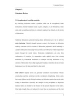
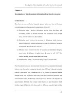
Fig. 1. Mass removal of Ferro L8 as a function of time at varying bath temperatures, due to the etching with a) P50, and c) P85, and two representative cross-sectional
SEM micrographs of Ferro L8 LTCC etched at 90 °C for 120 min with b) P50, and d) P85. e and f) Comparison of dissolution rates when etching Ferro L8 with different
solutions. For comparison, the results of NaOH etching experiments are also inserted (empty triangles).
viscosity of the etchant is a crucial parameter for the etching process,
and consequently, individual etching bath parameters influencing this
fluid parameter need to be taken into account. The viscosity of liquids
decreases with increasing bath temperature, and subsequently, the
diffusion of the etchant into the depth of the LTCC is facilitated, and
thereby the weight loss increases when rising the temperature. This
effect can be observed in the mass loss trends for both P50 and P85 at
temperature above 105 °C was avoided, while for the P85 with a
nominal boiling temperature of 154 °C [49], a maximum bath temperature of 120 °C was applied.
The calculated mass removal as a function of etching time at different bath temperatures for both P50 and P85 etchants is depicted in
Fig. 1. Since a suitable etching process particularly requires the penetration of the etchant into the pores and openings of the LTCC, the
3
Microporous and Mesoporous Materials 288 (2019) 109593
A. Hajian, et al.
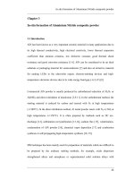
corresponding activation energies continuously decrease when increasing the etching time, the calculated activated energies with values
ranging from 0.63 eV for long etching times up to 1.89 eV for 5 min
etching are well above the limit of the diffusion-controlled regime, i.e.,
0.2 eV. Therefore, it can be concluded that for the etching reaction with
P50 solution, the process is reaction-controlled. Also, it should be
mentioned that since at low bath temperatures the etching reaction is
significantly slower. Therefore, dp values are reduced, and the impact of
potential error sources is more pronounced, resulting in a larger deviation of the fitted straight lines from the data points.
By increasing the etching time, the depth of etchant penetration
increases and the diffusion into the deep pores of the LTCC becomes
more and more dominating but does not reach the pure diffusion-controlled regime. For the P85 solution, however, as can be seen in Fig. 2d,
there is not a clear trend in the slopes of the fitted lines with etching
time, which might be due to the enhanced temperature dependence of
the P85 viscosity compared to that of P50, thus strongly affecting the
diffusion ability. Nonetheless, the calculated activation energies for all
etching times stay significantly above 0.2 eV (between 1.05 and
1.59 eV) suggesting a dominating reaction-controlled mechanism also
for this etchant.
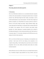
To acquire detailed information about the microstructure of the
substrate, Raman-based investigations were conducted to correlate the
change in LTCC constituents due to the etching process. The investigated samples were LTCC substrates etched with P50 solution at
90 °C at different etching times of 5, 15, 30, 60, 120, and 180 min. Since
the etching rate at low temperatures is very slow and at high temperatures difficult to control, Tb of 75 and 90 °C were chosen as representative etching temperatures for further analyses of the porosified
LTCC substrates. For reasons of comparison, the as-fired LTCC was also
subjected to the Raman measurements. The corresponding Raman
spectra are shown in Fig. 3. Each spectrum in this figure is an average of
180 spectra which have been obtained from the cross-section of the
LTCC substrates with a step size of 1 μm. In the Raman spectra, major
peaks corresponding to rutile (TiO2), corundum (Al2O3), and celsian
(BaAl2Si2O8) phases are detected. These minerals were identified based
on RRUFF Database [51] and also due to the prior knowledge about the
tape composition via ICP-OES measurements where the composition of
as-fired Ferro L8 was identified as 42.97% Al2O3, 30.45% SiO2, 16.37
BaO, 6.52 B2O3, 2.67 CaO, and 1.02 TiO2 (wt%).
For the as-fired sample, sharp peaks observed at Raman shifts below
200 cm−1 as well as small peaks observed at 509 cm−1 and 358 cm−1
are related to the crystalline celsian phase. By increasing the etching
time, the intensity of these peaks decreases, and finally they disappear,
which represents the celsian removal due to the etching process. The
peaks at 600, 450, and 220 cm−1 which are attributed to the rutile
phase, and also the peaks at 380, 420, and 640 cm−1 remain almost
unaltered within the measurement accuracy. Based on the well-known
acidic dissolution reaction of anorthite (CaAl2SiO8) [52,53], the following reaction is proposed for the celsian dissolution in LTCC:
different bath temperatures. Similarly, direct comparison of the weight
loss values for P50 with those for P85 shows that for the less concentrated solution (i.e., P50), the weight losses are significantly higher
due to the lower viscosity.
Moreover, based on the obtained gravimetric results, the normalized rates of dissolution for etching with both P50 and P85 solutions
were calculated, and the results are depicted as a function of bath
temperatures (see Fig. 1e). Both etchants show a very similar trend, in
which the dissolution rate is slightly increasing up to 75 °C, whereas at
higher temperatures, a higher increase is observed. Nonetheless, due to
the less difficult penetration into the openings and pores of the substrate, for all bath temperatures, the dissolution rate for P50 is significantly higher in comparison with P85.
Moreover, the calculated dissolution rates for etching with phosphoric acid are compared with those gained with an alkaline NaOH
solution having different concentrations between 0.5 and 6 mol L−1
[50]. In the latter study, it is reported that the etching is composed of
two main regimes being either pure porosification or partial dissolution
of the substrate. A comparison of all etching results shows that the P50
solution results in the highest rate of dissolution except for the 6 M
NaOH.
When choosing enhanced values of key NaOH etching parameters
such as concentration, etching time, and bath temperature, the etching
mechanism changes from predominant porosification to the substrate
dissolution regime. This is not favorable for the intended purpose because the maximum porosification depth has been already reached, and
after passing that critical etching time mainly complete dissolution is
taking place. However, due to the formation of wider pore openings,
the rate of dissolution is increasing intensely. Unlike for etching Ferro
L8 with alkaline NaOH solution [50], no significant reduction in the
substrate thickness was observed while etching with phosphoric acid,
independent of the etchant concentration. This indicates that the
etching of Ferro L8 in phosphoric acid solution results in a pure porosification, while etching with NaOH resulted in both surface porosification and partial dissolution of the substrate.
Porosification depth values as a function of etching time for both
P50 and P85 are plotted in Fig. 2a and b. For both etching solutions, at a
given temperature, depth of porosification increases with etching time.
For P50 etching solution, the slope is steeper at short etching times and
then becomes flatter showing that the porosification at the beginning of
the etching process is fast, due to the facile diffusion of the etchant into
the surface-near porosity. Because of the more difficult exchange of the
etching solution through the generated micro- and nanopores at the
etch front, the dissolution rate slows down, but does not reach any
saturation level. On the other hand for P85, because of the less pronounced diffusion affinity, the slopes are smaller than those for P50.
Increasing the etching bath temperature for a fixed etching time results
in increased dp values what is due to the faster reaction kinetics and also
easier penetration of the etchant into the depth of the LTCC body. By
further increasing the bath temperature to 105 °C, an almost linear
relationship is observed between dp and t until complete porosification
of the substrate is reached after 180 min. Please note that the reported
dp values are only taken from one side of the substrates.
To verify the assumption on the presence of two dominating etching
regimes, Arrhenius-type diagrams of dp as a function of the reciprocal
bath temperature were plotted, so that the activation energy (Ea) was
determined for fixed etching times through a linear regression procedure. The calculated Ea values were used to acquire further information
about the etching mechanism because, in a wet chemical etching process, Ea values of about 0.2 eV and below represent the domination of
diffusion-controlled, while higher Ea values indicate the presence of
reaction-controlled dissolution mechanisms [37,50].
Time-dependent evolution of Ea for etching Ferro L8 is represented
in Fig. 2c and d, and it can be observed that the porosification with P50
follows the Arrhenius law over the whole temperature range up to
240 min. Although the slopes of the linearly fitted lines and hence, the
BaAl2SiO8 + 8H+ → Ba+2 + 2Al+3 + 2H4SiO4
In order to investigate the etching behavior into the substrate depth,
individual Raman spectra are shown in Fig. 4 when analyzing their
cross-section and starting at the surface (i.e. depth of 0 μm). Since
showing all 180 spectra will be inconvenient to distinguish the small
peak changes due to the etching process, only some selected spectra
which are of interest to estimate the depth characteristics are shown.
For the interpretation of the obtained results, however, it is worth
mentioning that LTCC is a composite of ceramic grains heterogeneously
embedded in a glass matrix. Therefore, minor differences in the spectra
of a similar region even for the as-fired LTCC are reasonable, what is the
reason why the averaged spectra were shown in Fig. 3. But, it is also
intended to track the significant peak changes into the depth of the
LTCC. Therefore, the etching depth was estimated from the
4
Microporous and Mesoporous Materials 288 (2019) 109593
A. Hajian, et al.
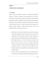
Fig. 2. Porosification depth dp and corresponding Arrhenius diagrams when etching Ferro L8 with P50 (a and c), and P85 (b and d) solutions at different etching
times. The Ea values determined from the linearly fitted lines are inserted in the figures. The R-square values for the linear fitting are also given in brackets.
120 min no or only weak celsian-related peaks were found at the surface. However, at a certain depth (approximately 70 μm), these peaks
are getting perceivable. Nevertheless, for the sample etched for
240 min, which represents the maximum etching depth, no significant
peak associated with the celsian phase was observed at any depth which
shows that through a highly selective celsian dissolution, the whole
substrate has been porosified. These results are in a reasonable agreement with the dp values obtained from cross-sectional SEM images as
well as with those obtained from TEM investigations, which will be
discussed next.
For microstructural analyses of Ferro L8 after porosification, the
cross-sectional image of an LTCC substrate is shown in Fig. 5a. On top, a
platinum layer is deposited, which is applied to reduce any charging
effects and to avoid structural damaging of the sample surface during
FIB preparation. As it can be seen, discrete alumina grains are distributed in the whole glass matrix, and the etchant penetrates via small
grain-near gaps and openings into the LTCC body. Therefore, it can be
concluded that this portion of the matrix is very important for enabling
the penetration of the etchant into the LTCC body and the realization of
deeply etched samples. Nonetheless, due to the depth limitations of the
FIB technique, the large penetration depths which were obtained in this
work cannot be fully displayed. Hence, for studying the depth of porosification, cross-sectional SEM images of fracture planes of the LTCC
were used.
In the next step, the obtained FIB foil was subjected to transmission
electron microscopy (TEM) and scanning transmission electron microscopy (STEM) investigations. Fig. 5b shows corundum grains and partially dissolved grain-near regions in a high angle annular dark field
scanning transmission electron microscopy (HAADF-STEM) image.
The chemical composition of the LTCC was explored through an
Fig. 3. Raman spectra normalized to the maximum of the band in the Q-range,
for as-fired LTCC and substrates etched with P50 at Tb = 90 °C. Each spectrum is
an average of 180 individual measurements.
disappearance of the peak at 404 cm−1 which was most sensitive to the
dissolution. Three representative samples i.e. as-fired, partially etched
(120 min), and totally etched (240 min) are shown. For the as-fired
substrate, except for the small peak found at large Raman shifts, the
characteristic spectra remain unchanged. For the sample etched for
5
Microporous and Mesoporous Materials 288 (2019) 109593
A. Hajian, et al.
EDX line scan which is indicated by an arrow. The corresponding EDX
spectra and quantifications with respect to the elements Al, Si, Ba/Ti,
and O are shown in Fig. 5c. In these spectra the counts of Si and Al
change in opposite directions representing corundum grains and the
glass matrix, respectively. The intermediate area corresponds to the
partially attacked or depleted celsian phase.
The celsian phase which has been crystallized from the glass matrix
during liquid-phase sintering, and its dominant removal due to the
etching process, are more clearly observable in the recorded bright field
TEM images (BFTEM) in Fig. 6. In addition to the chemical composition
and morphology of the LTCC, its crystallographic structure was explored in selected areas with Selected Area Electron Diffraction (SAED)
measurements. The SAED patterns for three representative positions
were recorded, and the results are shown in the lower row of Fig. 6.
Position 1 represents the amorphous glassy matrix, while positions 2
and 3 correspond to the crystalline corundum and celsian phase, respectively. Position 2 shows a typical single crystalline diffraction
pattern, while in position 3 in addition to the diffraction pattern, which
is far out from a low-indexed zone axis, concentric blunt circles are seen
indicating the polycrystalline morphology.
Mechanical characterization — As it was already illustrated, by employing the wet chemical etching process a defined porosity can be
introduced to the LTCC although the high penetration of the etchant
into the depth of LTCC may also raise concerns about the mechanical
robustness of the LTCC. Therefore, a detailed study was carried out on
the stiffness behavior of the LTCC substrates. For this purpose, as-fired
and porosified LTCC substrates were subjected to DMA analyses.
Substrates treated for different etching times, corresponding to different
depths of porosification, were chosen. First, the samples etched with
P50 at 90 °C were investigated. However, for this etching condition, the
reaction rate is so high that within an etching time of 20 min, the
stiffness of substrates decreases by about 90%, and after that, the
samples become too fragile to handle and to measure. To have a lower
reaction rate and better control on the depth of porosification, samples
etched at an etching temperature of 75 °C were chosen.
Furthermore, along with the LTCC substrates with a thickness of
about 180 μm, another set of substrates with a thickness of about
520 μm were used, as they represent two typical thicknesses in LTCC
substrate technology. Results of room temperature analyses for both
sets of 180 and 520 μm thick samples are shown in Fig. 7.
Independent of substrate thickness, the stiffness of both samples sets
decreases with etching time due to the mass removal and the introduction of air up to a certain depth into the LTCC body. However, for
the 520 μm thick samples due to the lower percentage of mass removal
in comparison to the 180 μm thick samples, the decrease with respect to
their corresponding as-fired samples is with about 40% lower compared
to 80%. This confirms that choosing thicker multilayered substrates for
the etching experiments secures to a higher degree the original mechanical properties after porosification.
DMA scans of the as-fired and etched LTCC samples indicate almost
constant values for all substrates up to measurement temperatures of
550 °C, which means that the proposed method does not limit the application of the LTCC even at such elevated temperatures (see Fig. 8).
After the DMA test, the samples were taken for cross-sectional SEM
imaging to measure the porosification depth values and correlate the
measured storage moduli with the different sample thicknesses.
Therefore, the measured porosification depth values were normalized
to the substrates thickness, and the resulting plot is shown in Fig. 9a.
Both sets of substrates follow a very similar trend in the decrease of
stiffness. However, for the thicker substrates due to the reduced percentage of the porosified area, the decrease in stiffness is also less.
Basically, this plot is independent of the sample thickness, etching time,
and etchant temperature.
In order to be able to predict the correlation between storage
modulus E′ and the relative porosification depth, a modification of wellestablished minimum solid area (MSA) models was employed. These
Fig. 4. Raman spectra normalized to the maximum of the band in the Q-range,
for the as-fired LTCC and substrates etched with P50 for different times at
Tb = 90 °C. All spectra were normalized to their overall area. Red spectrum is
related to the estimated maximum depth of porosification, dp. The values given
next to the spectra represent the depth at which the spectrum is aquired. (For
interpretation of the references to colour in this figure legend, the reader is
referred to the Web version of this article.)
6
Microporous and Mesoporous Materials 288 (2019) 109593
A. Hajian, et al.
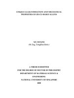
Fig. 5. a) Cross-sectional view on the microstructure of Ferro L8, and b-d) HAADF-STEM image with the corresponding EDX line profiles across a partially porosified
section of the Ferro L8 LTCC etched with P50 for 30 min at Tb = 90 °C.
Fig. 6. TEM images of a porosified LTCC substrate with three labeled locations for SAED analyses. At position 1, amorphous glass can be observed, whereas position 2
and 3 represent crystalline corundum and celsian phase, respectively.
7
Microporous and Mesoporous Materials 288 (2019) 109593
A. Hajian, et al.
time and bath temperature, solely by knowing the depth of porosification which can be measured straightforwardly by cross-sectional
SEM imaging, assuming a homogeneous porosity within the etched
layer.
Hence, for obtaining a given storage modulus, the substrate thickness and etching conditions can be carefully chosen to acquire the appropriate relative depth of porosification. Therefore, these results
confirm the applicability of the proposed etching method for obtaining
porosified LTCC substrates with tailored mechanical properties by
choosing the suitable depth of porosification for a substrate of the desired thickness.
4. Conclusions
Porosification of Ferro L8 LTCC through wet-chemical etching
process was studied in detail. Phosphoric acid with different concentrations of 85 wt% and 50% were applied as etchants at different
bath temperatures and treatment times. The process was so fast that
even for 5 min etching a considerable etching depth was reached.
However, the rate of the etching process and hence, the degree of
porosification, and the corresponding depth of porosification can be
precisely tailored by a careful selection of etching parameters including
etchant concentration, bath temperature, and treatment time. The high
surface quality of the porosified LTCC allows for a high-quality metal
deposition, which is essential for the reliable operation of high performance, high-frequency devices. Therefore, the focus of our next
study would be on the realization of high-quality metallic structures
serving, e.g. as antenna elements and on the corresponding changes in
dielectric properties due to the etching process.
Kinetic studies were conducted through gravimetric investigations
and analyses of the porosification depth, which show a higher reaction
rate for the less concentrated etchant solution and a dominating reaction-controlled mechanism. Further investigations prove the selective
dissolution of celsian phase, which is surrounding corundum grains,
thereby a very deep porosification up to the whole substrate thickness
could be realized.
Moreover, the stiffness behavior of the substrates subjected to this
wet-chemical etching process was investigated for substrates with two
different thicknesses. The result shows that for the applications where
high mechanical strength of LTCC are desired, the desired mechanical
properties are secured when choosing thicker substrates. Also, the
mechanical strength of the porosified LTCC substrates was investigated
over a large temperature range up to 550 °C indicating a constant storage modulus within the measurement accuracy. This demonstrates that
the proposed method does not limit the application of porosified LTCC
Fig. 7. Room temperature storage modulus of Ferro L8 substrates with two
different thicknesses of 180 and 520 μm etched with P50 at 75 °C for different
etching times. The results for 180 μm thick LTCC etched at 90 °C are shown for
comparison.
models are typically used to describe the porosity-dependency of
Young's modulus E in ceramic materials by the relationship E = E0 e-bP.
Here, E0 is the modulus of the non-porous base material, P is the total
porosity, and b is a fitting factor which is, in part, affected by the type of
pore structure [54]. Here, the model was modified by introducing a
modified porosity P′ = (dp/L)∙Pl, which takes into account the relative
porosification depth (dp/L), whereas L is the thickness of the substrate
and Pl the porosity within the etched layer.
For a total porosity within the etched layer of Pl = 0.2, which was
estimated by mercury intrusion porosimetry measurements of comparable specimens [55], a fit convergence as shown in Fig. 9b is
achieved with E0 = 100.5 ± 4.0 GPa and b = 11.5 ± 1.0, the former
value is in good accordance to values of the as-fired Ferro L8 as reported
in the material datasheet [45]. Also, a b value of 11.5 hints towards a
pore structure derived by stacking of solid spheres [54]. This type of
structure can be confirmed by cross-sectional SEM images showing the
continuous removal of the celsian phase during etching while solid
particles primarily consisting of alumina remain.
Consequently, these findings can be applied for a direct estimation
of elastic sample properties of Ferro L8 LTCC with P50 for any etching
Fig. 8. The temperature-dependent storage modulus of Ferro L8 substrates with two different thicknesses of a) 180, and b) 520 μm, etched with P50 at 75 °C for
different etching times.
8
Microporous and Mesoporous Materials 288 (2019) 109593
A. Hajian, et al.
[2] Z. Di, P. Li-Xia, Q. Ze-Ming, J. Biao-Bing, Y. Xi, Novel ultra-low temperature co-fired
microwave dielectric ceramic at 400 degrees and its chemical compatibility with
base metal, Sci. Rep. 4 (2014) 5980.
[3] S. Arcaro, F.R. Cesconeto, F. Raupp-Pereira, A.P. Novaes de Oliveira, Synthesis and
characterization of LZS/α-Al2O3 glass-ceramic composites for applications in the
LTCC technology, Ceram. Int. 40 (2014) 5269.
[4] Y. Imanaka, Multilayered Low Temperature Cofired Ceramics (LTCC) Technology,
Springer Science & Business Media, New York, 2005.
[5] Y. Li, X. Zhu, J. Liu, L. Zhou, Z. Wang, Miniaturization of low temperature Co-fired
ceramic packaging for microwave filters, 19th International Conference on
Electronic Packaging Technology, ICEPT), 2018, p. 1524.
[6] C.S. Martínez-Cisneros, N. Ibáđez-García, F. Valdés, J. Alonso, Miniaturized total
analysis Systems: integration of electronics and fluidics using low-temperature Cofired ceramics, Anal. Chem. 79 (2007) 8376.
[7] J. Xiong, Y. Li, Y. Hong, B. Zhang, T. Cui, Q. Tan, S. Zheng, T. Liang, Wireless LTCCbased capacitive pressure sensor for harsh environment, Sensor Actuator Phys. 197
(2013) 30.
[8] L. Lin, M. Ma, F. Zhang, F. Liu, Z. Liu, Y. Li, Fabrications and performance of
wireless LC pressure sensors through LTCC technology, Sensors 18 (2018) 340.
[9] L. Lin, M. Ma, F. Zhang, F. Liu, Z. Liu, Y. Li, Integrated passive wireless pressure and
temperature dual-parameter sensor based on LTCC technology, Ceram. Int. 44
(2018) S129.
[10] Q. Tan, T. Luo, T. Wei, J. Liu, L. Lin, J. Xiong, A wireless passive pressure and
temperature sensor via a dual LC resonant circuit in harsh environments, J.
Microelectromechanic. Syst. 26 (2017) 351.
[11] U. Schmid, A robust flow sensor for high pressure automotive applications, Sensor
Actuator Phys. 97–98 (2002) 253.
[12] U. Schmid, G. Krötz, D. Schmitt-Landsiedel, A volumetric flow sensor for automotive injection systems, J. Micromech. Microeng. 18 (2008) 045006.
[13] Q. Tan, W. Lv, Y. Ji, R. Song, F. Lu, H. Dong, W. Zhang, J. Xiong, A LC wireless
passive temperature-pressure-humidity (TPH) sensor integrated on LTCC ceramic
for harsh monitoring, Sensor. Actuator. B Chem. 270 (2018) 433.
[14] L. Manjakkal, K. Zaraska, K. Cvejin, J. Kulawik, D. Szwagierczak, Potentiometric
RuO2–Ta2O5 pH sensors fabricated using thick film and LTCC technologies, Talanta
147 (2016) 233.
[15] H.E. Amor, A.B. Kouki, P. Marsh, K.T. Kim, H. Cao, Development of a Novel
Miniaturized LTCC-Based Wireless pH Sensing System, SENSORS 2016 IEEE, 2016,
p. 1.
[16] M. Ma, H. Khan, W. Shan, Y. Wang, J.Z. Ou, Z. Liu, K. Kalantar-zadeh, Y. Li, A novel
wireless gas sensor based on LTCC technology, Sensor. Actuator. B Chem. 239
(2017) 711.
[17] A. Brandenburg, J. Kita, A. Groß, R. Moos, Novel tube-type LTCC transducers with
buried heaters and inner interdigitated electrodes as a platform for gas sensing at
various high temperatures, Sensor. Actuator. B Chem. 189 (2013) 80.
[18] M. Štekovič, J. Šandera, Fabrication of electrochemical sensor in low temperature
Co-fired ceramics, Proceedings of the 2014 37th International Spring Seminar on
Electronics Technology, IEEE, 2014, p. 81.
[19] E.S. Fakunle, Z.P. Aguilar, J.L. Shultz, A.D. Toland, I. Fritsch, Evaluation of screenprinted gold on low-temperature Co-fired ceramic as a substrate for the immobilization of electrochemical immunoassays, Langmuir 22 (2006) 10844.
[20] P. Sturesson, L. Klintberg, G. Thornell, Pirani microgauge fabricated of high-temperature co-fired ceramics with integrated platinum wires, Sensor Actuator Phys.
285 (2019) 8.
[21] E. Remiszewska, K. Malecha, J. Kruk, J. Jankowska-Śliwińska, W. Torbicz,
A. Samluk, K.D. Pluta, D.G. Pijanowska, Enzymatic method of urea determination in
LTCC microfluidic system based on absorption photometry, Sensor. Actuator. B
Chem. 285 (2019) 375.
[22] J. Luo, R. Eitel, Sintering behavior and biocompatibility of a low temperature cofired ceramic for microfluidic biosensors, Int. J. Appl. Ceram. Technol. 14
(2017) 99.
[23] K. Malecha, The implementation of fluorescence-based detection in LTCC (LowTemperature-Co-Fired-Ceramics) microfluidic modules, Int. J. Appl. Ceram.
Technol. 13 (2016) 69.
[24] J. Luo, T. Dziubla, R. Eitel, A low temperature co-fired ceramic based microfluidic
Clark-type oxygen sensor for real-time oxygen sensing, Sensor. Actuator. B Chem.
240 (2017) 392.
[25] K. Malecha, E. Remiszewska, D.G. Pijanowska, Surface modification of low and high
temperature co-fired ceramics for enzymatic microreactor fabrication, Sensor.
Actuator. B Chem. 190 (2014) 873.
[26] K. Malecha, D.G. Pijanowska, L.J. Golonka, W. Torbicz, LTCC microreactor for urea
determination in biological fluids, Sensor. Actuator. B Chem. 141 (2009) 301.
[27] B. Cao, H. Wang, Y. Huang, J. Zheng, High-gain L-probe excited substrate integrated cavity antenna array with LTCC-based gap waveguide feeding network for
W-band Application, IEEE Trans. Antennas Propag. 63 (2015) 5465.
[28] R. Faddoul, N. Reverdy-Bruas, A. Blayo, Formulation and screen printing of water
based conductive flake silver pastes onto green ceramic tapes for electronic applications, Mater. Sci. Eng., B 177 (2012) 1053.
[29] T. Tajima, H. Song, M. Yaita, Compact THz LTCC receiver module for 300 GHz
wireless communications, IEEE Microw. Wirel. Compon. Lett. 26 (2016) 291.
[30] F. Sickinger, C. Sturm, L. Janda, O. Stejskal, M. Vossiek, Automotive satellite radar
sensor system based on an LTCC miniature frontend, IEEE MTT-S International
Conference on Microwaves for Intelligent Mobility, ICMIM), 2018, p. 1 2018.
[31] A. Bittner, H. Seidel, U. Schmid, Permittivity of modified polyimide layers on LTCC,
Microelectron. Eng. 88 (2011) 2977.
[32] Y. Yashchyshyn, K. Godziszewski, P. Bajurko, J. Modelski, M. Szafran, E. Bobryk,
E. Pawlikowska, G. Tarapata, J. Weremczuk, R. Jachowicz, Tunable ferroelectric
Fig. 9. a) Storage modulus of Ferro L8 substrates with two different thicknesses
of 180 and 520 μm etched with P50 at 75 °C for different etching times indicating results which are independent of the etching conditions. The results for
180 μm thick LTCC etched at 90 °C are shown for comparison. b) The relation
between storage modulus and the relative depth of porosification can be adequately described by an exponential fit function, assuming a porosity of 20%
within the etched layer based on mercury intrusion porosimetry results.
at least up to this temperature level. Finally, a straightforward correlation, independent of the etching conditions, between the mechanical
properties and the relative porosification depth is presented. This very
practical relationship can help to optimize in a straightforward approach the suitable depth of porosification to achieve the desired substrate stiffness.
Acknowledgments
The authors would like to acknowledge the financial support from
both the Austrian and German Science Fund: FWF No. I 2551-N30 and
DFG LI2713/1-1.
References
[1] J.M. Mánuel, J.J. Jiménez, F.M. Morales, B. Lacroix, A.J. Santos, R. García,
E. Blanco, M. Domínguez, M. Ramírez, A.M. Beltrán, D. Alexandrov, J. Tot,
R. Dubreuil, V. Videkov, S. Andreev, B. Tzaneva, H. Bartsch, J. Breiling, J. Pezoldt,
M. Fischer, J. Müller, Engineering of III-nitride semiconductors on low temperature
Co-fired ceramics, Sci. Rep. 8 (2018) 6879.
9
Microporous and Mesoporous Materials 288 (2019) 109593
A. Hajian, et al.
[33]
[34]
[35]
[36]
[37]
[38]
[39]
[40]
[41]
[42]
Digest, MTT), 2013, p. 1.
[43] J.J. Jiménez, J.M. Mánuel, H. Bartsch, J. Breiling, R. García, H.O. Jacobs, J. Müller,
J. Pezoldt, F.M. Morales, Comprehensive (S)TEM characterization of polycrystalline
GaN/AlN layers grown on LTCC substrates, Ceram. Int. 45 (7) (2019) 9114.
[44] G. Gold, K. Helmreich, A physical model for skin effect in rough surfaces, 7th
European Microwave Integrated Circuit Conference2012, IEEE, 2012, p. 631.
[45] L8 LTCC Tape System, Technical Data Sheet, Ferro Corporation, 2013.
[46] C.A. Schneider, W.S. Rasband, K.W. Eliceiri, NIH Image to ImageJ: 25 years of
image analysis, Nat. Methods 9 (2012) 671.
[47] M.D. Abràmoff, P.J. Magalhães, S.J. Ram, Image processing with ImageJ, Biophot.
Int. 11 (2004) 36.
[48] K. Jlassi, M.M. Chehimi, S. Thomas, Clay-polymer Nanocomposites, Elsevier, 2017.
[49] W. van Gelder, V.E. Hauser, The etching of silicon nitride in phosphoric acid with
silicon dioxide as a mask, J. Electrochem. Soc. 114 (1967) 869.
[50] A. Hajian, D. Müftüoglu, T. Konegger, M. Schneider, U. Schmid, On the porosification of LTCC substrates with sodium hydroxide, Compos. B Eng. 157
(2019) 14.
[51] B. Lafuente, R.T. Downs, H. Yang, N. Stone, The power of databases: the RRUFF
project, Highlights in mineralogical crystallography, Walter de Gruyter GmbH2016,
pp. 1-29.
[52] L. Li, C.A. Peters, M.A. Celia, Effects of mineral spatial distribution on reaction rates
in porous media, Water Resour. Res. 43 (2007) W01419.
[53] E.H. Oelkers, J. Schott, Experimental study of anorthite dissolution and the relative
mechanism of feldspar hydrolysis, Geochem. Cosmochim. Acta 59 (1995) 5039.
[54] R.W. Rice, Use of normalized porosity in models for the porosity dependence of
mechanical properties, J. Mater. Sci. 40 (2005) 983.
[55] A. Hajian, S. Smetaczek, C. Zellner, M. Stöger-Pollach, T. Konegger, A. Limbeck,
U. Schmid, Tailored and deep porosification of LTCC substrates with phosphoric
acid, J. Eur. Ceram. Soc. 39 (10) (2019) 3112.
ceramic-polymer composites for sub-THz applications, 2013 European Microwave
Conference, IEEE, 2013, p. 676.
T. Fukasawa, M. Ando, T. Ohji, S. Kanzaki, Synthesis of porous ceramics with
complex pore structure by freeze-dry processing, J. Am. Ceram. Soc. 84 (2001) 230.
T. Isobe, T. Tomita, Y. Kameshima, A. Nakajima, K. Okada, Preparation and
properties of porous alumina ceramics with oriented cylindrical pores produced by
an extrusion method, J. Eur. Ceram. Soc. 26 (2006) 957.
K. Prabhakaran, A. Melkeri, N.M. Gokhale, S.C. Sharma, Preparation of macroporous alumina ceramics using wheat particles as gelling and pore forming agent,
Ceram. Int. 33 (2007) 77.
Y.S. Dzyazko, Y.M. Volfkovich, V.E. Sosenkin, N.F. Nikolskaya, Y.P. Gomza,
Composite inorganic membranes containing nanoparticles of hydrated zirconium
dioxide for electrodialytic separation, Nanoscale. Res. Lett. 9 (2014) 271.
A. Bittner, U. Schmid, The porosification of fired LTCC substrates by applying a wet
chemical etching procedure, J. Eur. Ceram. Soc. 29 (2009) 99.
A. Hajian, M. Stöger-Pollach, M. Schneider, D. Müftüoglu, F.K. Crunwell,
U. Schmid, Porosification behaviour of LTCC substrates with potassium hydroxide,
J. Eur. Ceram. Soc. 38 (2018) 2369.
F. Steinhäußer, K. Hradil, S. Schwarz, W. Artner, M. Stöger-Pollach, A. SteigerThirsfeld, A. Bittner, U. Schmid, Wet chemical porosification of LTCC in phosphoric
acid: anorthite forming tapes, J. Eur. Ceram. Soc. 35 (2015) 4181.
F. Steinhäußer, A. Talai, G. Göltl, A. Steiger-Thirsfeld, A. Bittner, R. Weigel,
A. Koelpin, U. Schmid, Concentration and temperature dependent selectivity of the
LTCC porosification process with phosphoric acid, Ceram. Int. 43 (2017) 714.
F. Steinhäer, K. Hradil, S. Schwarz, W. Artner, M. Stưger-Pollach, A. SteigerThirsfeld, A. Bittner, U. Schmid, Wet chemical porosification of LTCC in phosphoric
acid: celsian forming tapes, J. Eur. Ceram. Soc. 35 (2015) 4465.
A. Talai, F. Steinhäußer, U. Schmid, R. Weigel, A. Bittner, A. Koelpin, A finite 3D
field simulation method for permittivity gradient implementation of a novel porosification process in LTCC, 2013 IEEE MTT-S International Microwave Symposium
10